

When designing an amateur HF transceiver for a range of 160m, there was a task, such as navigating when setting up. A sufficiently accurate, convenient and attractive mechanical scale seemed unreasonably difficult to manufacture at that time, and a strong-willed decision was made to make a digital scale. That, in addition to the lack of fairly accurate mechanics, took up little space, fit well into the front panel of the proposed device and was practically not critical to the installation location in the device case, which greatly simplified the layout of the device.
Currently, a large number of electronic scales and frequency meters, the development of which uses microchips of varying degrees of integration. Often these are complex devices with several dozen microcircuits. These designs are quite difficult to repeat due to the fact that in a complex scheme there is a much higher chance of making a mistake at all stages - from development to installation. Attention was focused on devices made on the basis of modern microcontrollers (they are quite simple to program).
We studied the possible options available on the Internet, from them, an option was selected that was suitable for the availability of radio elements and complexity. It turned out to be a fairly well-known design of the frequency meter-digital scale A. Denisov. Take a look at her.
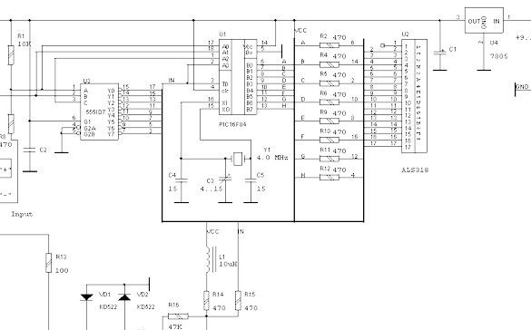
The heart of the circuit is the central processor U1, which performs the functions of measuring, calculating, transforming, controlling dynamic indication and dynamically polling input signals. Pins J3 and J4 are used to select the digital scale mode. The processor clock frequency is determined by the quartz resonator Y1 and can vary within small limits by the capacitors C3 and C4.
Chip U3 - decoder the position of the displayed digit.
Shaper of the input signal, made on the transistor VT1. The measured frequency signal applied to input J5 is limited, amplified, and fed to the processor PIC input for measurement.
Specifications:
The maximum measured frequency. ……………… 30 MHz
The maximum resolution of the measured frequency ... 10 Hz,
Input Sensitivity ………………………… .250 mV
Supply voltage ………………………………. 8 ... 12 V,
Current consumption ............................................. 35 mA,
The device functions are implemented as follows:
When the outputs are disabled, J3 and J4 works as a frequency meter (measurement mode);
When submitting a log. “0” to pin J3 adds the measured values to a constant written in non-volatile memory (digital scale);
When submitting a log. “0” to pin J4 modulo subtracts this constant from the measured value (digital scale);
When submitting a log. “0” simultaneously to pins J3 and J4 after 1 sec. the scale will switch to constant recording mode, display the letter "F" and the measured frequency.
Re-feed the log. "0" on J3 and J4 will lead to the recording of the measured value in the non-volatile memory of the processor and return to measurement mode. After that, the new constant will be used as the value of the intermediate frequency.
This mode is designed so that users can set the IF value on their own scale without reprogramming the PIC processor. By default, the IF value equal to 5.5 MHz is recorded in the program text.
Note a logical “0” corresponds to a potential of 0 volts (“ground”).
What was used.
Instruments.
Soldering iron with accessories. Tool for radio installation. Tools for drawing printed circuit boards. Something to drill, including thin (0.8mm) holes. Multimeter. Access to a computer is required. Used hot melt adhesive.
Materials
In addition to radio elements, a piece of foil-coated fiberglass, an assembly wire, chemicals for the manufacture of printed circuit boards were needed.
A good, but outdated indicator ALS-318 was used in the scheme. The indicator was specially created for use with microcircuits having a small output current. The numbers there were tiny and enough for him. So that the numbers could be seen, there was a plastic lens above each. It was visible normally, but the angle of view, of course, is small. Such a specific indicator. ALS-318 is a block of 9 such digits. It has not been released for a long time.
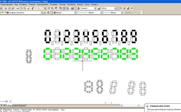
I had to look for a replacement for him. Unfortunately, in the local mountain-store of radio products, seven-segment indicators were not so rare, but at least 4 of the same ones ... Having dealt with some gloom, I decided to make such indicators myself - LEDs were offered, a whole showcase. Among them turned out to be quite suitable for compiling numbers, with a rectangular elongated body. But here came the overlay, the greens were not enough for eight digits, I had to, with a wave of my hand at aesthetics, pick up the red ones, but they weren’t enough either. Having secured the oaths of sellers that “no later than Monday” they would bring a dump truck of the same type, went to their home to engage in nanotechnology.
In the beloved AutoCAD, several variants of the "marking" of the digits composed of LEDs were drawn. Selected the cutest.
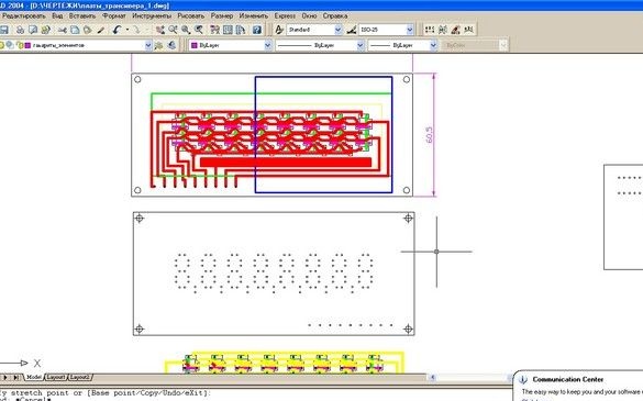
The circuit board of the frequency meter itself, it was decided to leave the copyright, and the circuit board with indicators, given the installation on the front wall of the device, plotted in the same AutoCAD.
Oh yes, the binary decoder chip has an output current of only 8 mA, I had to mess with transistor keys.
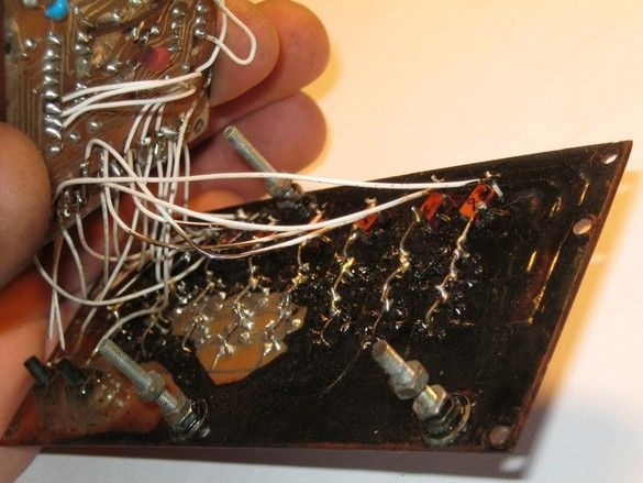
Eight KT361 transistors, each for each category, so as not to redo the frequency meter circuit board, are installed on the indicator board, on the side of the tracks. Contact pads are brought to them.
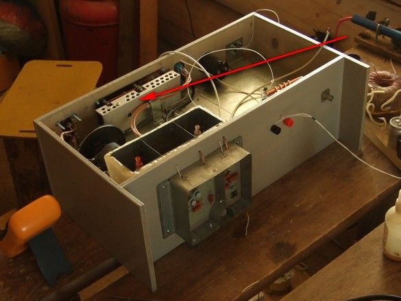
The frequency meter board was attached to indicators on racks made of M3 screws, a sort of sandwich. In the drawing above, this is a blue outline.
The programmer for PIC controllers was assembled and configured. I stopped at the option where a “high” voltage (13V) is supplied for programming. Connects to the parallel port of the computer.
Practice has shown its reliability and good performance.
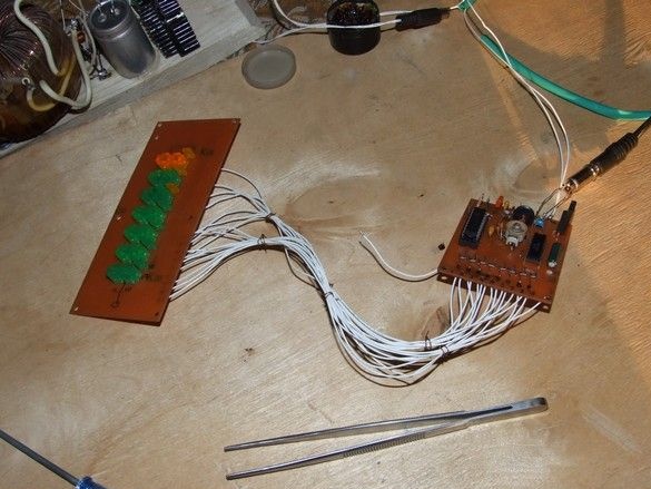
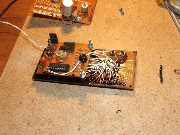
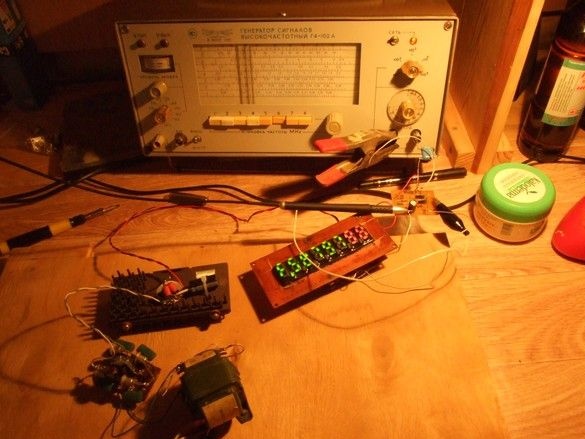
So, our PIC16F84 controller has been successfully “flashed”. The boards, the control unit itself and not completely the indicator, were assembled. All connections are made on a live thread, try.
He came to life as cute. True, at first I didn’t understand anything at all, the indicators are not read very well, to put it mildly, but you can still understand. And the "blinking" of their constant, somewhat embarrassed.
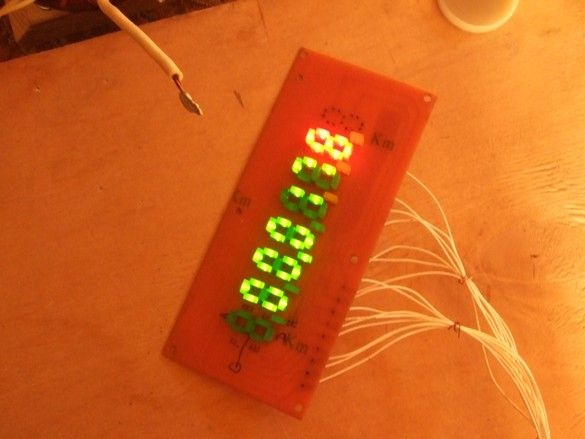
The signal comes from the sound card of the computer. The program generator program works. On the indicator 178 Hz.Unfortunately, nothing can be done with a “blink” - a dynamic indication.
Poor readability, partly due to the visibility of the non-luminous segments of the digit, partly due to the exposure of the luminous segment of the neighboring ones. First, it is neutralized classically - by a sufficiently dense light filter. For example, a sheet of printer paper placed on top of the indicator LEDs virtually eliminates this nuisance.
At the next run into the city, the missing number of LEDs was purchased and installed on the indicator board.
From the same exposure, it was decided to get rid of more radically.
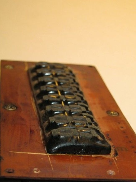
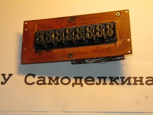
In the beginning, the indicator LEDs were painted with black bitumen varnish. I didn’t really like it, and the varnish shone through. If possible, he wiped it with solvent, and filled the space between the LEDs with black hot-melt adhesive. Oh, this, another thing! No translucency to you. Smudges of hardened glue, cut with a sharp knife under the ruler.
The protruding LEDs are sawn off with a large sandpaper glued to a bar. This, in addition to appearance, also gave a matte surface to the ends of the “segments”, which led to a much more uniform glow. In a word, it became very good.
The frequency meter was set up, which consisted in supplying a more or less accurate frequency to the input of the device and tuning the capacitor C3 until the correct readings on the indicator were obtained. One trimming capacitor was not done, I still had to change the capacitance C4, C5.
The control board is fixed to a large “indicator”, the lengths of the connecting wires are specified in place. “Clock” mode control buttons are glued to the back of the indicator board with hot-melt adhesive.
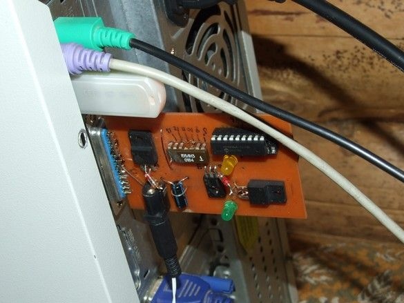
A frequency meter is mounted on the front wall of the transceiver being assembled. From the inside out. Outside, the numbers are covered with a wide plate of thin corrugated plexiglass (a piece of the printer tray), slightly tinted with diluted asphalt varnish. Under the filter is a layer of thick brass foil with a slotted rectangular window opposite the numbers. By the way, when working as part of a transceiver, the last two digits of a different color were very convenient. Important when tuning, the first five digits were, and the last two - hundreds and tens of hertz, no. And with their different colors, a short glance at the indicator was enough to understand its indications.
The stabilizer 7805 is equipped with an aluminum radiator.
For some time the transceiver worked in the “radio” mode, with an unsettled transmitting part (I do not have a call sign yet), then its digital scale was modernized.
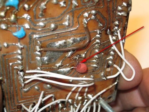
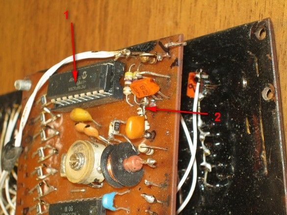
It consisted of modernization, first of all, replacing the processor from PIC16F84 to PIC16F628A (1, see figure) and introducing a new simple input driver on a two-gate field-effect transistor, plus several simple switching (2, see figure) on the main board and it’s clear, " firmware ”of the new processor.
After all the evolutions, the frequency meter, among other things, can still measure the period and duration of the pulses. Yes, the most, for my taste, pleasant - the somewhat annoying blinking of the indicator has practically disappeared.
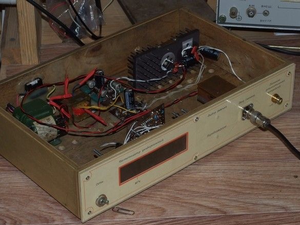
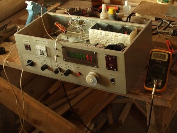
The need for a radio disappeared, and it was decided to make a separate case for the frequency meter, moreover, now it is so powerful with us.
The case is made of 8mm plywood, the front panel is printed on a color printer, on dense photo paper, a transparent plate of thin plexiglass is superimposed on top of it. The light filter on the indicators is two layers of plastic cut from a dark disposable eggplant.
The input shaper is fixed behind the input socket and is enclosed in a box soldered from sheet copper for shielding. With the main board, it is connected by a thin coaxial cable. In addition to the main power supply with a +5 V stabilizer, inside the case there is another small transformer with a rectifier and a +12 V stabilizer, on the bank.It is intended for powering various consoles to a frequency meter - measuring resonant frequencies of circuits, measuring inductance, capacitance, temperature, voltage.
Files with a more detailed description of the frequency meter, its refinement and programmer are located in the archive.
There you can also find firmware and a printed circuit board of the frequency meter.