

Hello to all lovers homemade, everyone who wanted to shoot a video on the street or two or three steps away from the camera, noticed that the recorded sound turned out to be too weak in terms of volume, and also had most of the unpleasant noises, such as wind and other extraneous sounds. I also encountered such a problem when it became necessary to record video, where in the frame I will stand a few meters from the camera. The solution was to take a microphone from some unnecessary device and make an amplifier for it to record sound remotely from the camera, and then synchronize it with the video track.
In order to make a lavalier microphone with an amplifier, we need:
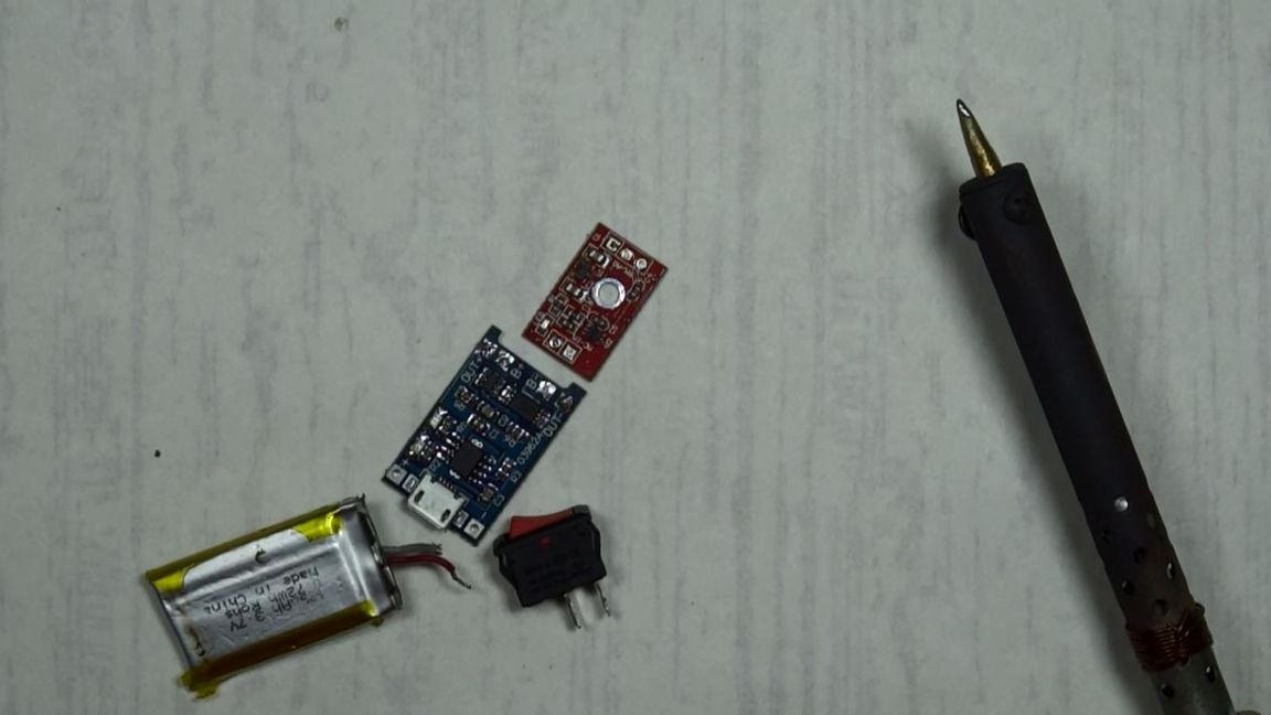
* MAX 9812 amplifier board purchased with aliexpress
* Charge controller board for 18650 batteries, also purchased abroad
* A couple of wires
* Soldering iron with flux and solder
* Battery 3.7 volts and a capacity of 195 milliamps
* Small plastic case, sizes 4 by 3cm
* Microphone capsule
* Three 3.5 mm plugs, one of them with 4 pins
* Two audio jacks for 3.5 mm plug
* Hot melt adhesive
* On / Off switch, preferably smaller
That's all the components that are needed to build a lapel microphone with an amplifier.
We smoothly move on to the step-by-step production of my homemade product, but before that I advise you to watch the video material that I shot specifically in order to make it clearer how to do this.
Step one.
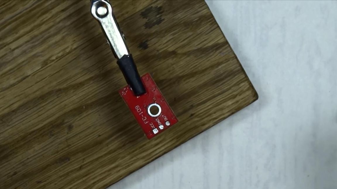
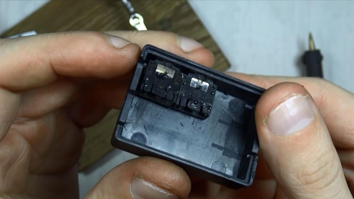
First of all, it is necessary to free the amplifier board, which came to me from China, from components that we don’t need, namely this is the electric microphone itself, which will come in handy in the future, but not on this board. You also need to remove the contacts of the connection of the amplifier board with the arduino module, since it was originally conceived for this.
Step Two
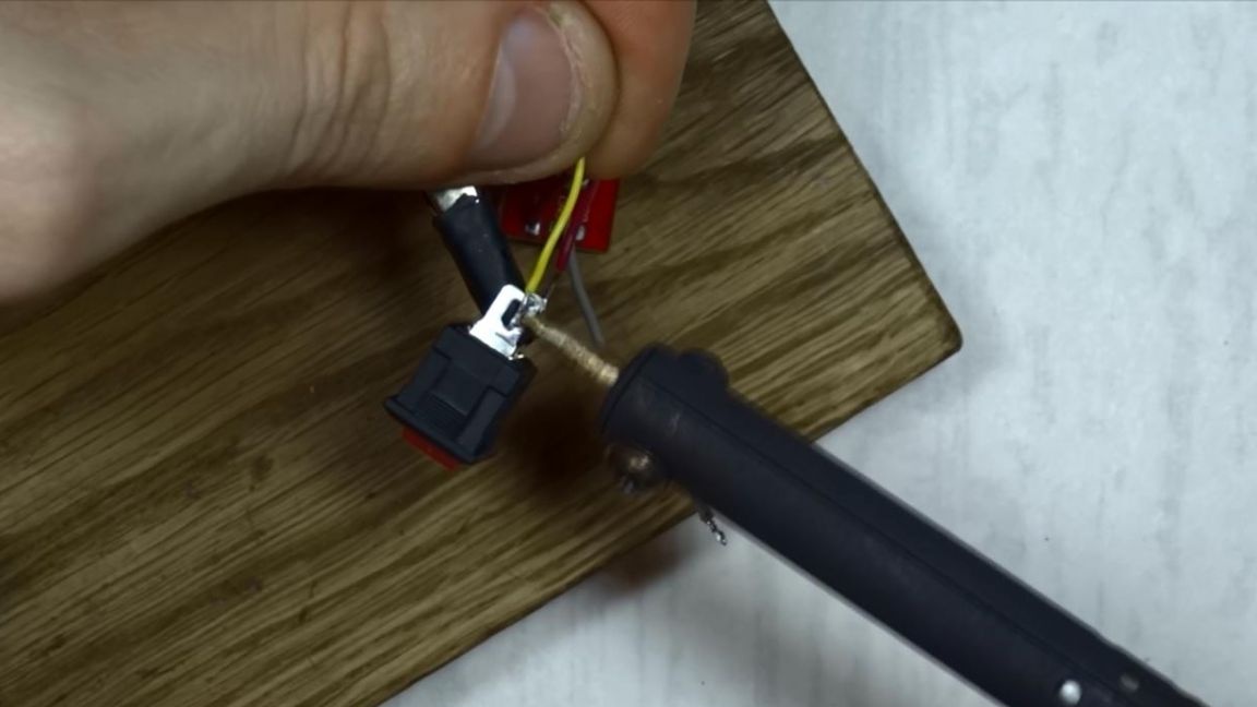
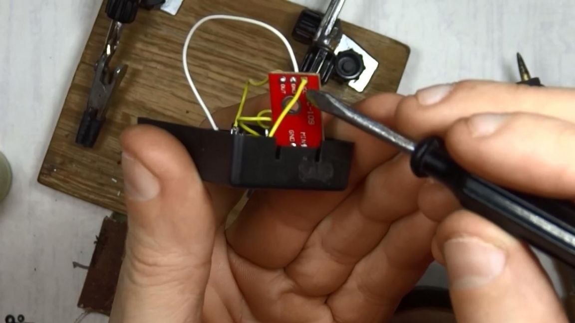
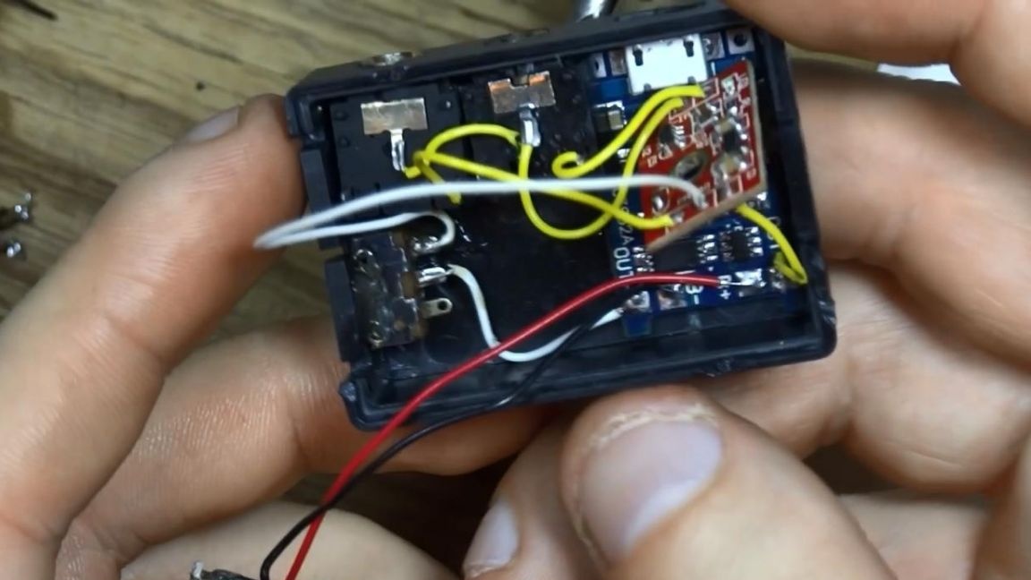
After the amplifier board is freed from unnecessary components on it, you can solder the wires to it. Armed with a soldering iron, it is advisable to use low-power soldering irons in order to prevent overheating of the board and the main chip, we solder the power wires to the tracks marked VCC + and GND -, that is, to plus and minus, respectively.
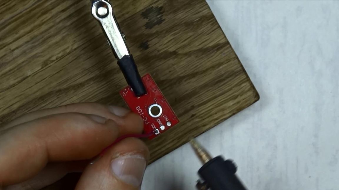
Now, in the gap to the positive contact, we solder the switch, which will disconnect our circuit if necessary.
Step Three
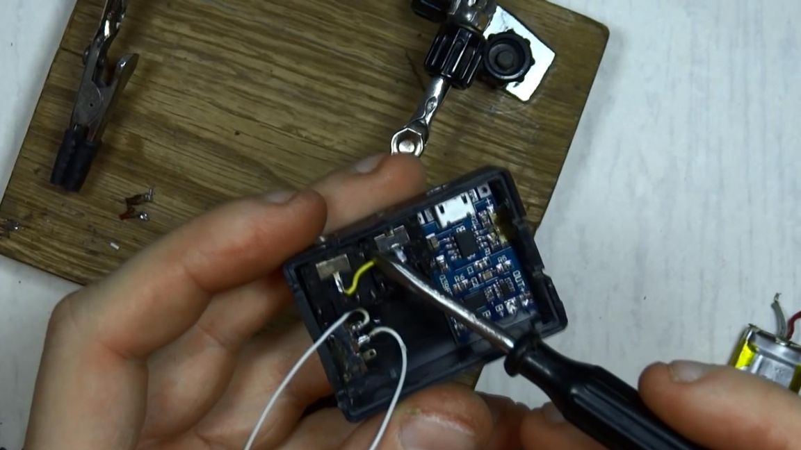
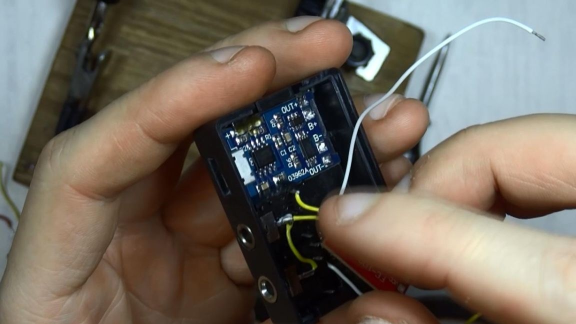
Now we will make a charger for this homemade product.I bought it on the aliexpress website, namely, the charge circuit for 18650 batteries. We solder the battery that I pulled out of a previously inoperative player, its voltage is 3.7 volts, and the capacity is 195 milliamps, which will be enough for such an undemanding power scheme. Solder the battery plus to pin B +, and minus to pin B-. Power from the amplifier will be supplied from the contacts OUT + and OUT -, that is, plus and minus, respectively.
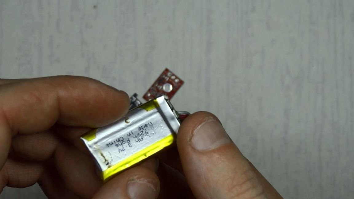
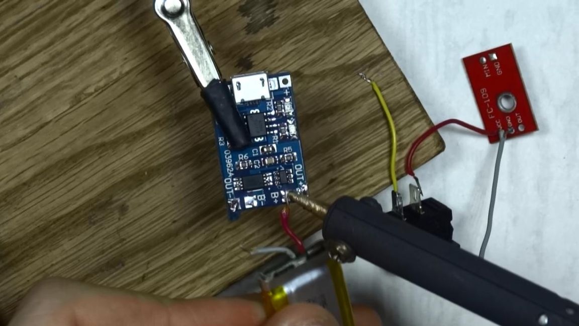
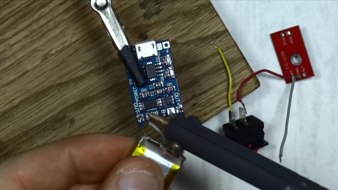
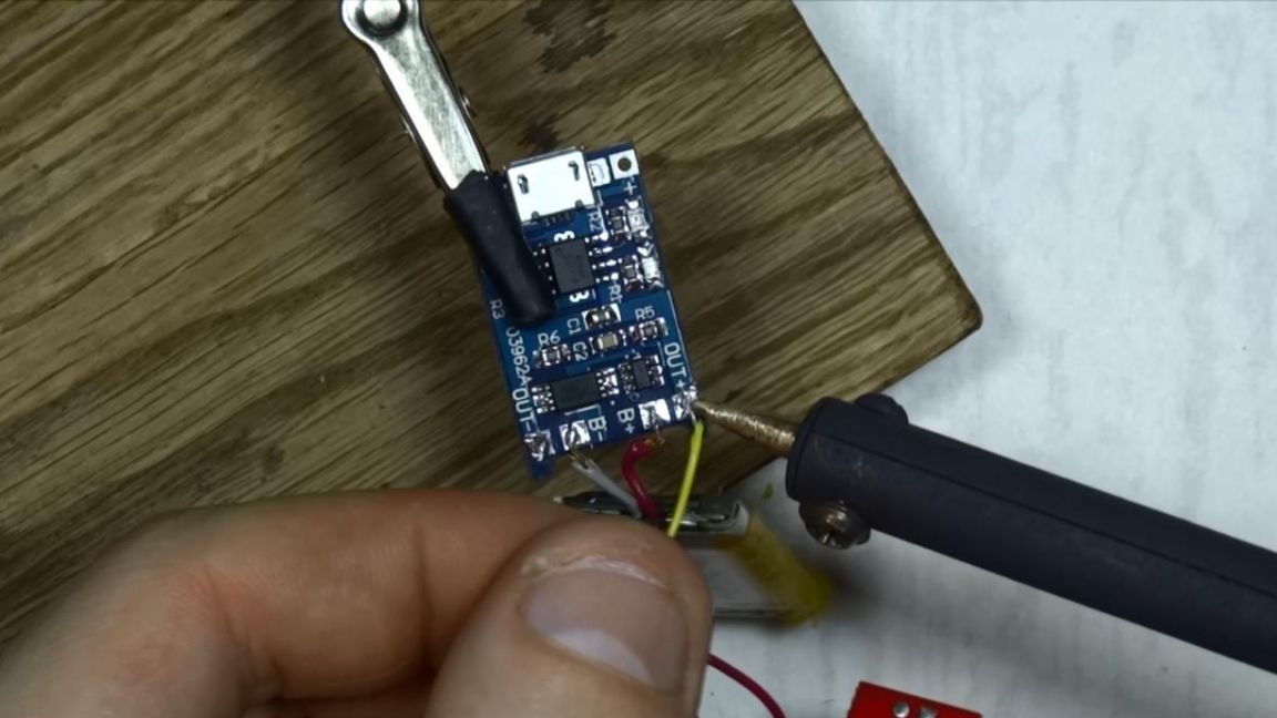
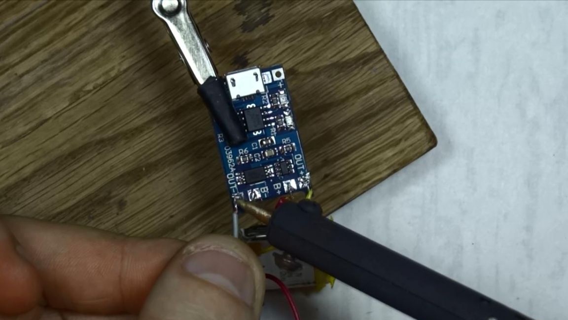
This charge circuit also provides for discharge control and does not allow the battery to completely discharge, which is very good.
Step Four
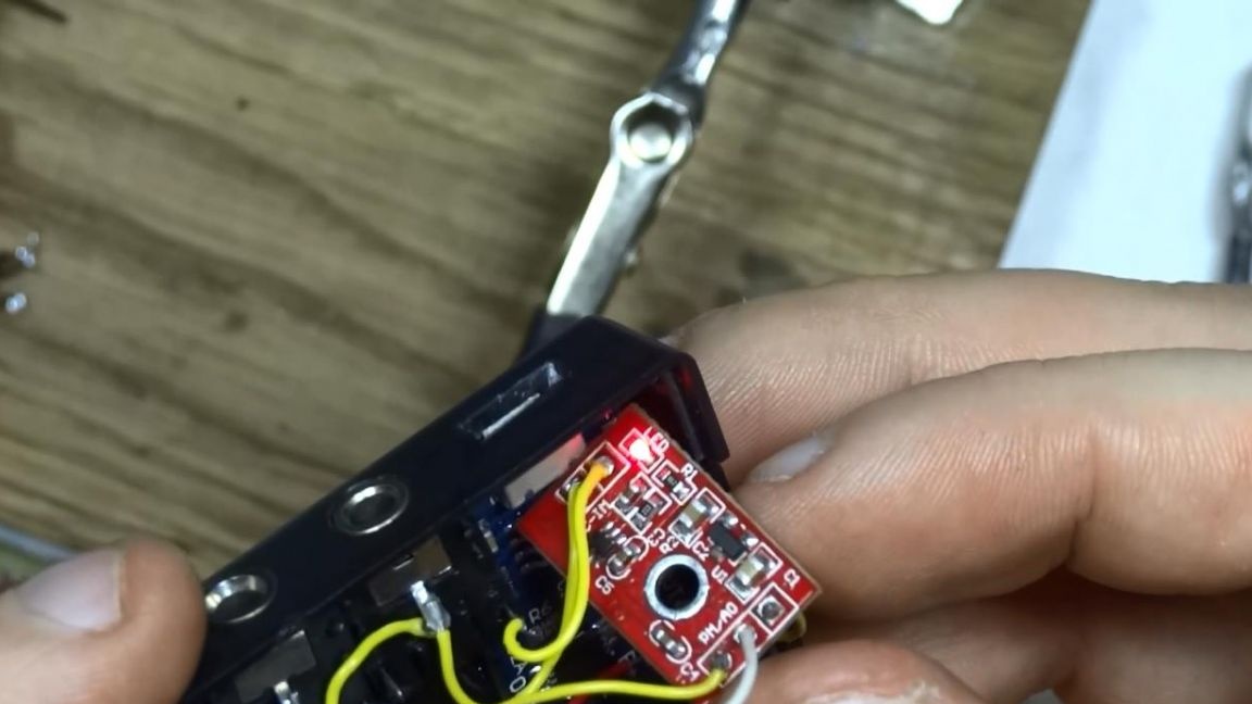
We check our assembled circuit, the operational state of the amplifier is accompanied by an indication of a light bulb, in this case it is a red LED, it needs to be brought out in the future to know if the amplifier is on or not. An amplifier also needs input and output.
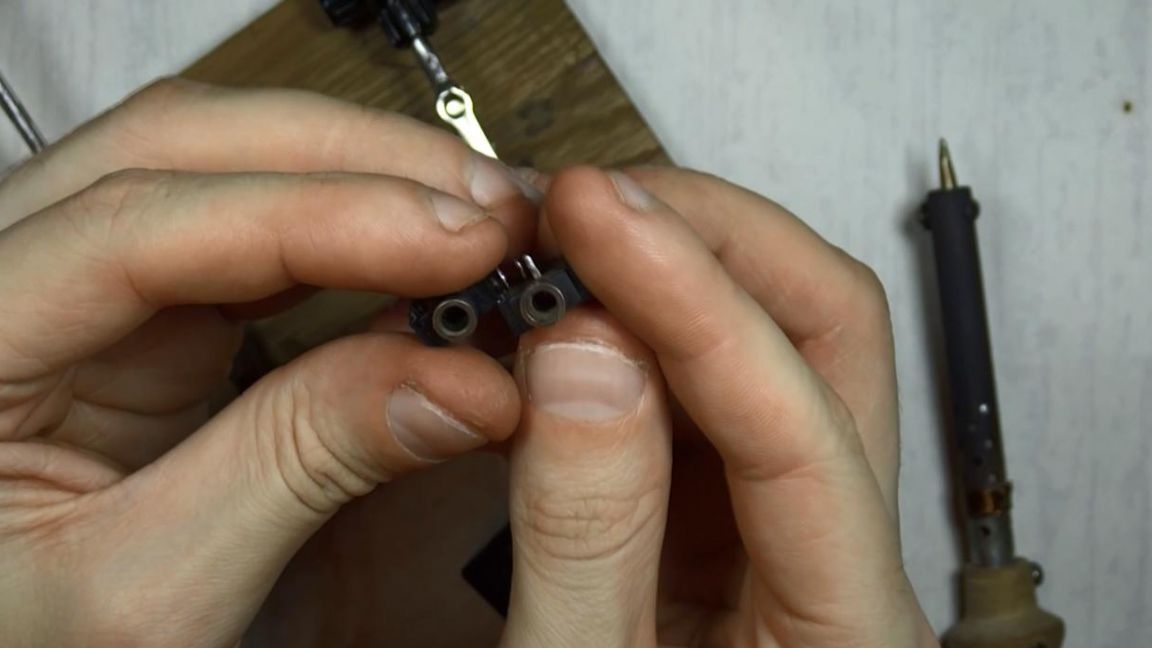
First, I installed the nests in the case itself with hot-melt adhesive in the pre-drilled holes. By input, I mean a jack with the ability to connect a microphone, and by output, a jack with the output of amplified sound from the lapel microphone itself, which goes directly to the recording device.
Therefore, at this stage, I took exactly two sockets for a 3.5 mm plug and soldered the contact going to the microphone to one of them, and connected the other plug with a wire to the sound output of the amplifier. Cons nests previously connected together.
Step Five
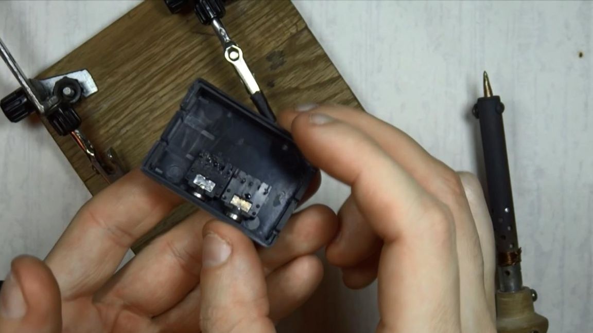
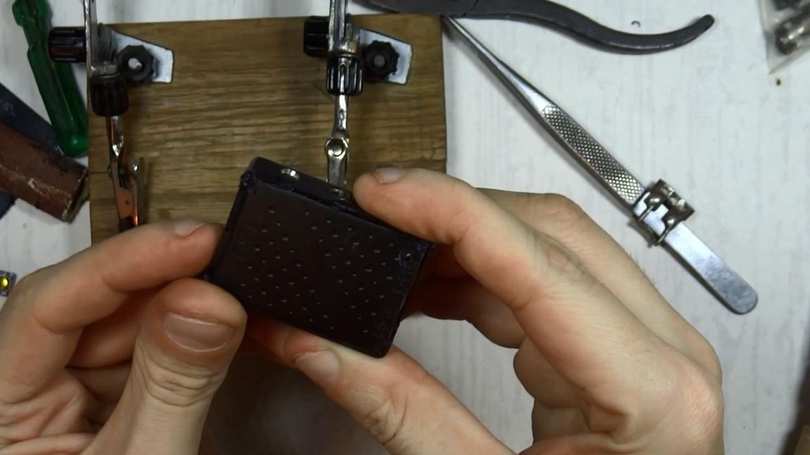
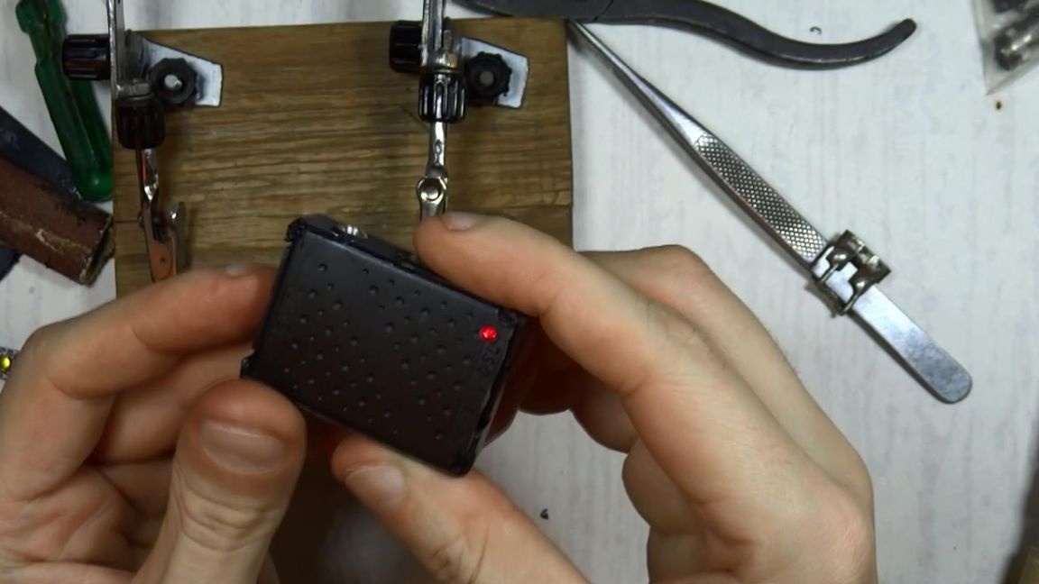
Now you need to put all the components in the case or, in other words, tamp. I also cut the entrance under the charging socket with a clerical knife, and recharge if necessary. On the side of the charge module, I made small holes near the charge indication lamps and filled it with hot glue, since it passes light well. When charging, the red LED is on, and when the battery is fully charged, it is blue. We close the lid of our little box, in advance I made a hole in it in order to see the LED of the amplifier, by the way, it is now also visible through transparent hot-melt adhesive.
Also signed with a soldering iron where the input is located, and where the sound output is, IN and OUT, respectively.
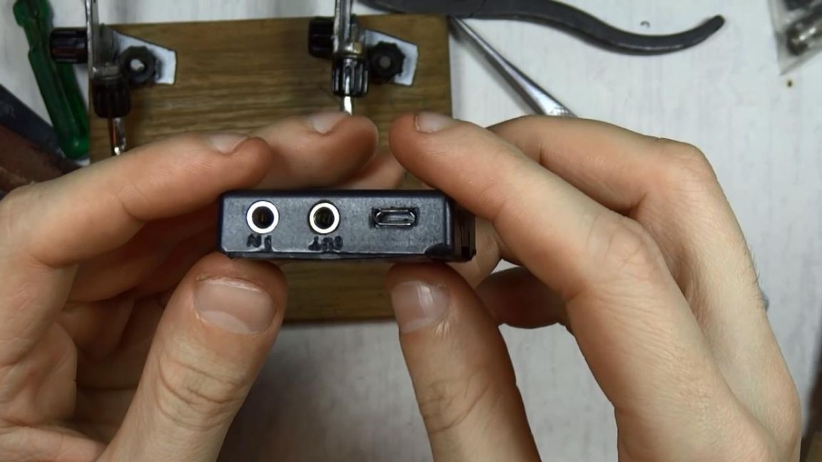
And next to the switch I turned ON and OFF, which I then changed to even more compact, since the past still could not be placed.
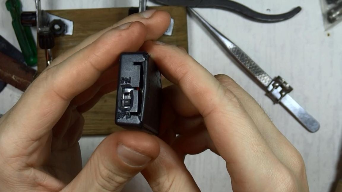
Plastic melted along the edges for reliability, as a result the case keeps well, but it didn’t influence the aesthetic component very well, but oh well, anyway this device will be hidden in your pocket for the most part.
Step Six
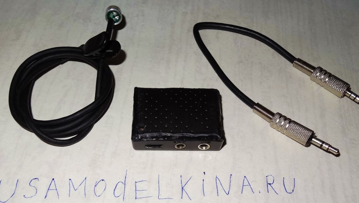
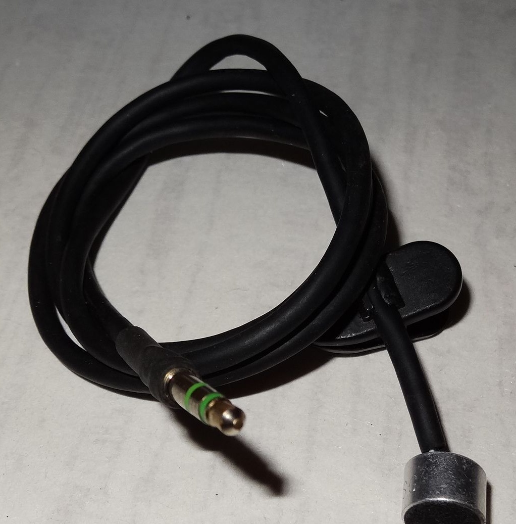
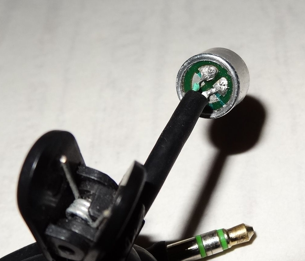
It's time to retrofit the amplifier, since without a microphone and plugs its use is reduced to zero. From the very microphone that I unsoldered at first, I assembled a small length microphone-buttonhole, which I trite soldered to the 3.5mm plug and installed a clip on the wire for convenience.
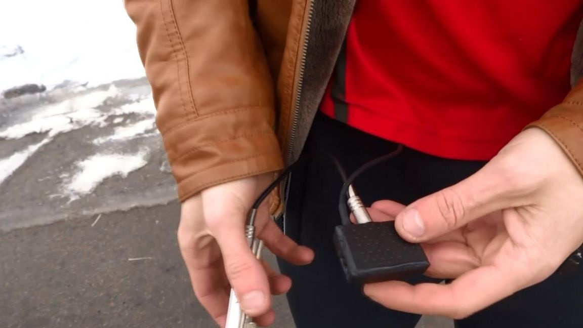
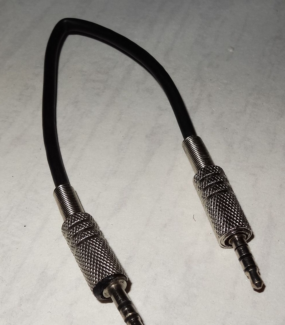
Also, to output sound to the recording device, I soldered a cable that has two 3.5mm plugs on both sides, but one of them with 4 contacts. All this is done in order to connect to the phone, since there is no microphone connected with 3 contacts. The 4th contact is responsible for the microphone and is usually used in the headset for conversations.
That's all for me, this lavalier microphone is completely ready, I already tested it in practice, the sound is written well, but note that the sound quality itself depends on what you are recording on, so you need to pay attention if you want to achieve high quality sound.
Also, when recording sound to this microphone, it is more convenient to make a clap at the beginning of the video, it will help you synchronize the video track with sound and help save a little time, this is an old blogging trick.
Thank you all for your attention and creative ideas.