

Frequency meter - the first, after a vulgar tester, device in the measuring laboratory of a radio amateur. Indeed, when designing and tuning equipment, the operation of which is based on the phenomenon of resonance in oscillatory circuits, it is vitally important to be able to measure the basic parameters of these very circuits. Moreover, a frequency meter equipped with simple attachments allows measuring capacitances of capacitors, inductors of coils, which is very useful in amateur radio practice. There are constructions of prefixes-converters that allow you to turn the frequency meter into a voltmeter-millivoltmeter, thermometer. It is not difficult to supplement the frequency meter on microcircuits with the stopwatch mode. Very accurate.
What can I say, this design was born to me a long time ago. A printed circuit board of the main module was made - the author's version from the description, the display board is its own, for other indicators. I drew the tracks by hand with a makeshift drawing pen from a needle from a medical syringe. Unfortunately, the wiring is quite tight, and even not to poison. Little bit. In some places the smallest conductors remained, like cobwebs, almost invisible to the naked eye. In a word, the design was not asked from the very beginning. The boards were assembled, but of course, the device did not work, fiddled with it a bit and left it - it was summer, the building season, and it was for the soul that I was busy in the evenings. Here you go. The assembled board gradually began to creep into parts, and until it finally creeped out, I decided to take it, still. Thoughtfully, step by step.
So. As for the scheme. Instrument circuits of this type have been repeatedly described in amateur radio literature. Each of them differs in nuances - the type of indication and the number of discharges, the construction of individual cascades, and the input shaper. The principle is that the operation of individual nodes is almost the same. The described device, in essence, is a kind of compilation of three similar ones.Take a look at what happened.
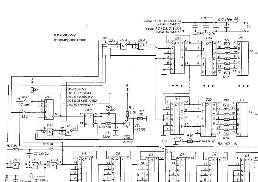
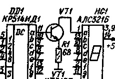
Scheme of the main unit [1]. In addition to the changes reflected in the diagram, the number of indicator bits is reduced to five, and transistor switches are introduced to control larger indicators [2] according to the diagram below.
The indicators are used KLTs 202A with a common anode, key transistors KT503.
The input driver circuit is taken from [3], the same detailed description of the operation of the nodes and the settings of this type of frequency meter are there.
What was used.
Tools, devices.
A set of tools for radio installation, a soldering iron with accessories, a multimeter. Joiner's tool for making the case, a jewelry jigsaw came in handy. A small bench tool. Anything for drilling holes, including small ones (~ 0.8 mm) on printed circuit boards, is better if it is a special microdrill or machine for such purposes, plus drills. Used hot melt adhesive. Construction dryer for working with heat pipes. A soldering iron with a capacity of about 60 watts, for structural soldering. To provide a test signal, it is convenient to use an RF generator. In some places, a drill, a small gas burner, came in handy.
Materials
In addition to radio elements, we used - pieces of foil material for printed circuit boards, different thermotubes, mounting wire, fasteners. Plywood for the housing. Galvanized steel sheet for the front panel, a piece of brass for decorative trim. Relevant chemicals, access to a computer with a printer.
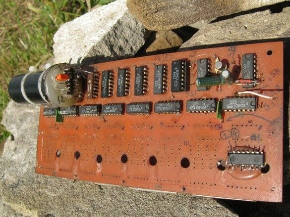
Board, the main unit of the frequency meter. Almost stolen for parts.
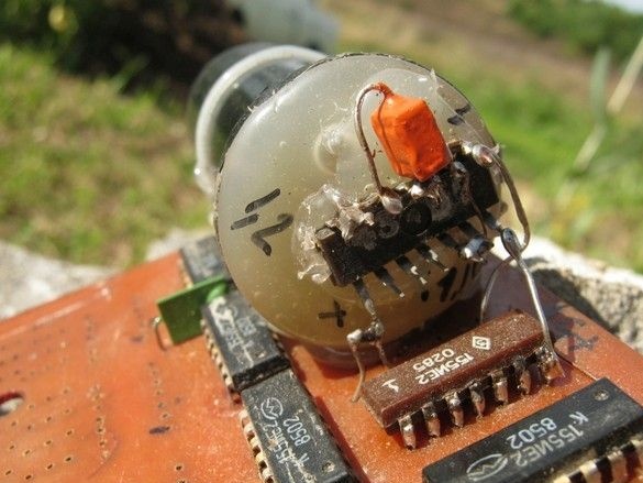
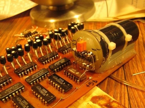
The master oscillator on 155LA3. A quartz resonator at 1 MHz is noteworthy. It is of monstrous size and placed in a metal case from a 6P9 radio tube. On top of the extruded marking “6P9”, “quartz” “1000kHz” is applied with white paint, well, there are all kinds of stars. Octal base, all things. The base, however, was torn off and hung on the wiring-conclusions, apparently, the previous owner also could not believe his eyes and picked to peek. But the container with the crystal is not depressurized. The base was torn off, in its place the hot glue slapped the microcircuit with his back. And for the gentle conclusions calmer and in the sense of layout is more correct.
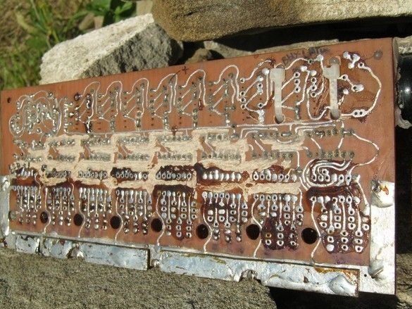
He cleaned the most dense and suspicious loops of tracks with a drill in favor of wall mounting, leaving only contact pads for the conclusions of elements from them.
He began to restore the board.
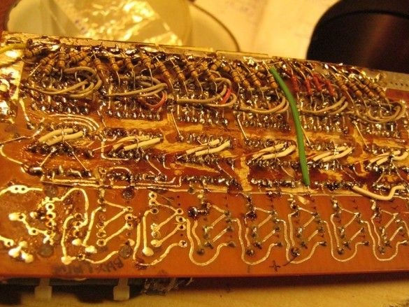
Spatial installation instead of flat - “printed”, looks surprisingly concise, which is explained by the possibility of overlapping conductors.
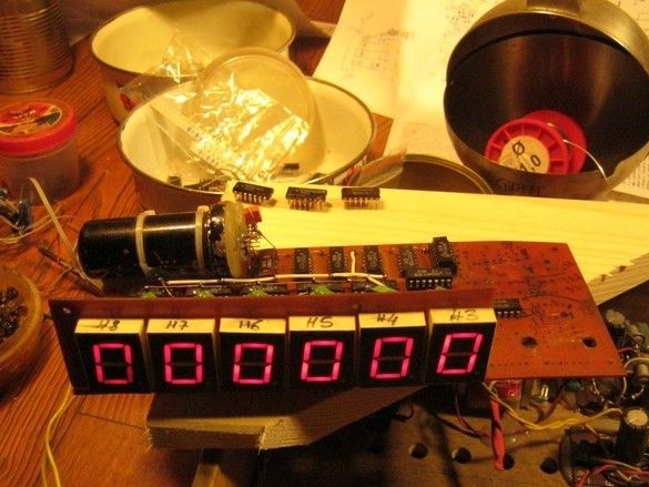
Turning on. Thoughtfully, sequentially block by block, methodically checking the work of each.
Nevertheless, it was decided to try to use all the categories.
I gave them a little pat - no, all the same, such an illumination is not very convenient. It is difficult to navigate in the indicator. You can get used to it, but it seems like there is no need - only the first three digits after the decimal point are important, the rest only get in the way and are needed only to exclude the measurement ranges from the switch circuit. Moreover, such a number of fairly powerful indicators, electricity eats, like a pig swill - +5 V, more amperes. 7805 is not happy with this, it is very hot. I had to use an external control transistor for it [4].
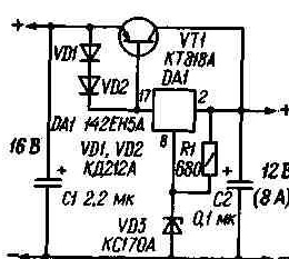
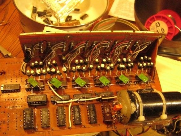
The circuit does not contain rare elements, such as current-measuring resistors and works well. The stabilization voltage VD3 is 6.8 V. It is advisable to install the transistor and diodes on one radiator, close to each other.
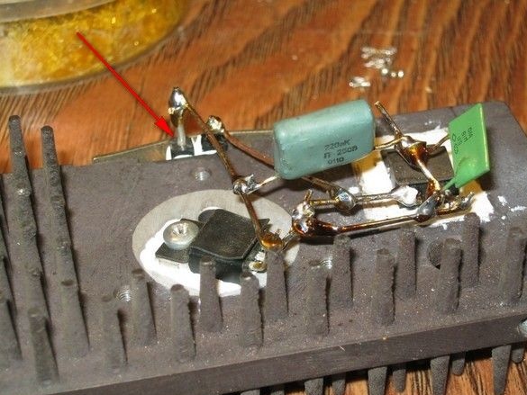
This is what my performance looks like. The arrows indicate the diodes VD1,2 - IN5822, for a more snug fit to the radiator, their cylindrical bodies are filed on an emery to a square section. Do not forget to touch the surfaces in contact with the radiator, plunge a little thermal paste to reduce thermal resistance.
The stabilizer showed itself well in operation, the heating of the microcircuit was significantly reduced.
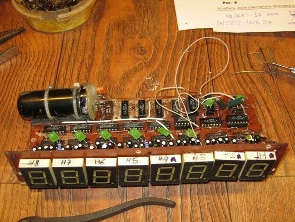
According to the test results, it was decided to reduce the number of indicators to 5 and introduce a switch of two ranges, as in [5]. This will allow for convenient indication, not to reduce the range of measured frequencies. The current consumption will also greatly decrease.
Here, on a piece of the breadboard, the input driver was assembled and configured. The maximum frequency that was able to measure about 15 MHz.
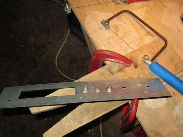
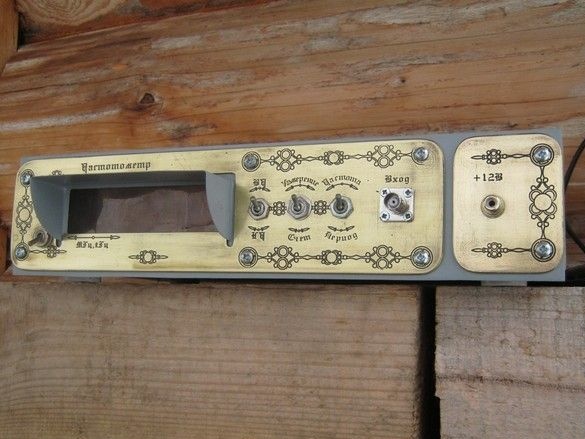
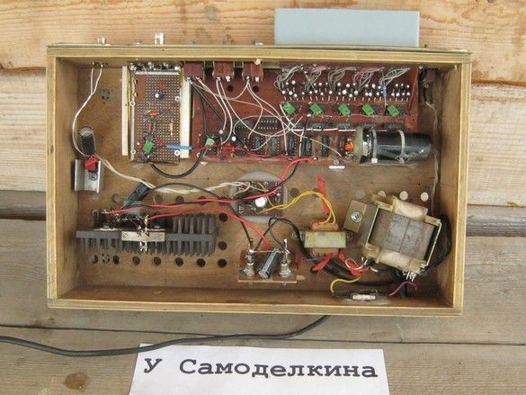
The frequency meter was mounted in an already finished 8mm thick plywood box. The front panel to hide the traces of all intermediate options was made of galvanized steel roofing 0.5mm. The windows are cut out by my favorite tool. For some “revitalization”, a visor-hood is soldered over the indicators, again, the light will not interfere.
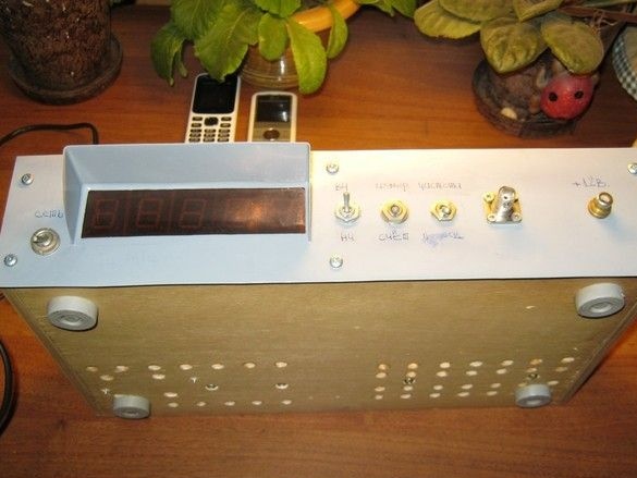
Mm, no, it turned out pretty dull anyway, and writing with a felt-tip pen is a bad manners. A number of options were considered, dwelling on etched brass nameplates, as a further development - an overlay decorative panel with inscriptions.
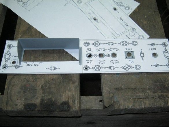
Several options for panels and inscriptions themselves were drawn in AutoCAD, and decorative elements were added at the same time. The panel, to clarify the dimensions, was printed at a scale of 1: 1, holes and windows were cut with a scalpel. Their sizes and positions were clarified, corrected in the CAD, printed again ... In a word, by the method of successive iterations.
After that, by contact printing, the image was transferred to a blank with a photographic varnish, etched, and an artificial patina was applied.
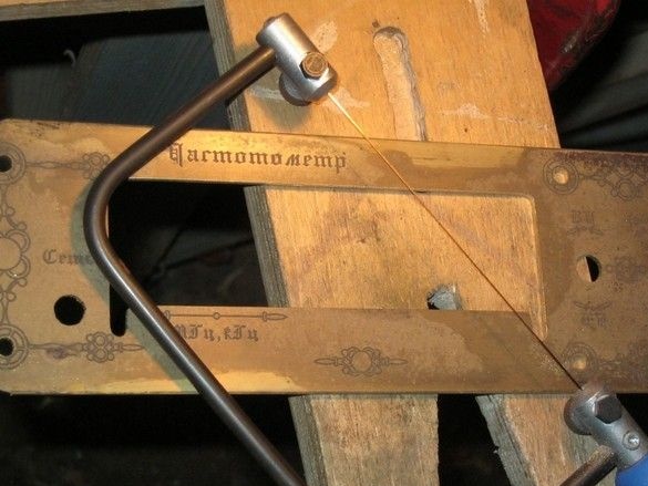
My favorite tool again.
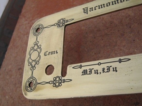
And now the finished panel. It remains to cover it with transparent nitro-varnish for protection against oxidation and can be installed.
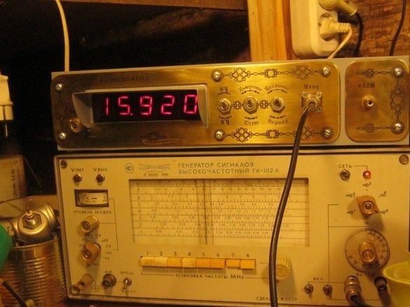
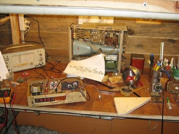
All installation elements in place, final assembly. The frequency meter was able to measure megahertz more, which, apparently, is explained by minimizing the length of the wires and some ordering of the installation.
1. Universal frequency meter. Ivanov A. Radio Designer No. 4.5 2007
2. TURNING ON THE POWERFUL SEMI-ELEMENT LED INDICATORS.
3. Frequency meter on K155 microcircuits.
4. The use of microcircuit stabilizers.
5. The frequency meter is electron-counting.