Illumination for seedlings, or as they say, additional illumination is a question that every season makes us think not only of beginners, but also of experienced summer residents. Of course, you can do without backlighting, but it is thanks to it that plants at a very early age receive more chances of survival and resistance to growth in open ground.
Artificial lighting of most plants is required during their maintenance in regions with short daylight hours. It is used when keeping plants on window sills, with direct sunlight for less than 4 hours and in regions where cloudy weather prevails. Additional light in many respects determines the success of the development of healthy and strong plants.
The advantages of additional illumination are:
- prolonged daylight hours, which is especially true for early seedling cultivation;
- additional light provides comprehensive coverage of plants, thereby preventing the stretching of plants and their deformity;
- providing plants with the necessary spectrum guarantees their optimal phased development to adult crops.
Practice confirms the necessity and importance of clarifying seedlings of all cultures. But it is also proved that the backlight does not show a positive effect when it is irregular, because, including the lamps only “when you remember”, you will only harm the plants by knocking down their biorhythms.
To ensure optimal development and growing seedlings in early spring, it is proposed to manufacture a device that automatically turns on additional artificial lighting while reducing natural light. This will allow the plants to extend the daylight hours smoothly and without gaps, in any weather outside the window. Also, to create favorable conditions for plant growth, a moisture sensor and an indicator of the need for watering are included in the device.
The circuit of the device is built on a DD1 chip of type K561TL1 containing four “NAND” elements with Schmitt trigger properties. On three elements (DD1.1-DD1.3) the photo relay is assembled. The light sensor is a photoresistor SF3-1 (R1). Together with a variable resistor R2 and a constant R3, the sensor forms a voltage divider, depending on the level of illumination.
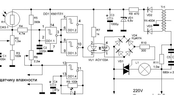
On the Schmitt trigger DD1.1 made threshold element. The threshold is regulated by a variable resistor R2. Capacitor C1 increases the noise immunity of the device. Capacitor C2 eliminates false alarms during short-term exposure of the photoresistor. In parallel, the elements DD1.2 and DD1.3 provide the necessary logic of operation, greater clarity of switching and a guaranteed current for the operation of the LED of the optocoupler VU1.
With a decrease in illumination below a predetermined R2 level, the resistance of the photoresistor increases to the threshold of operation of the inverters and the LED of the optocoupler VU1 turns on. The thyristor opens and through the VD4 diode bridge opens the triac VS1. The source of artificial light turns on.
On the element DD1.4 of the microcircuit, a humidity indicator is assembled. The soil resistance between the sensor electrodes, depending on its moisture content, together with a variable resistor R6 (humidity level control) and a constant R5 form a voltage divider. When the soil dries, its resistance increases, the signal from the divider is fed to terminal 12 DD1.4 and, when the threshold element is switched, it allows the operation of an economical low-frequency pulse generator with output to LED1.
The DD1 chip is powered by a rectifier on VD2, VD3, a voltage stabilizer on a zener diode VD1 and a capacitor C3. The consumption of the control circuit on the DD1 chip is 7 ... 8 mA, the consumption of the device from the network in standby mode is 20 mA.
Due to the fact that the device operates from a 220 volt network and uses electrodes included in moist soil, for safety reasons, it is required to completely eliminate the galvanic connection of the device control circuit from the network. For this, the output part of the photo relay controls the power triac VS1 through the optocoupler VU1, and the power circuit of the control circuit is separated from the network by an isolation transformer Tr1.
1. The power supply of the control circuit.
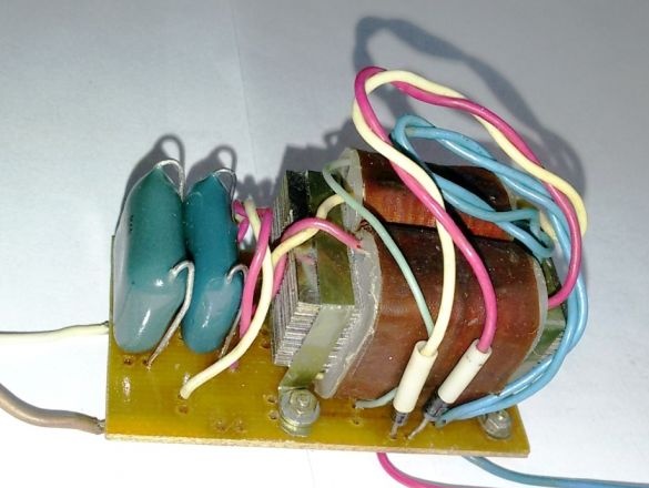
Since a small current is required to power the control circuit (up to 20 ma), we will construct the power supply using a combined circuit. We extinguish the excess voltage with the help of a capacitor of 0.33 microfarads x 500V (two serially connected capacitors C5 and C6 of 0.68 microfarads x 250V each), and then sequentially turn on a small step-down transformer for an input voltage of 30 ... 40 volts (for example, from a subscriber speaker).
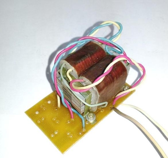
We install the transformer on a PCB board. Next we solder the capacitors and the windings. In the presence of a transformer with a midpoint in the secondary winding, we replace the diode bridge with two diodes in accordance with the above diagram.
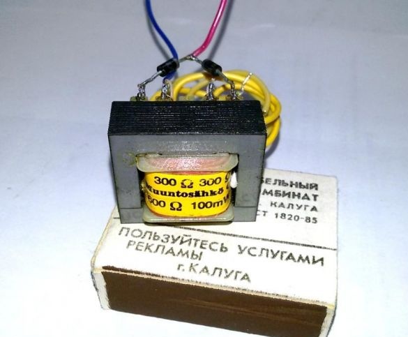
Also, the operation of the device according to the above diagram was checked, using a transformer with a capacity of 100 MW, there were no problems with heating or current load.
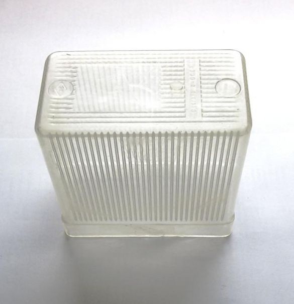
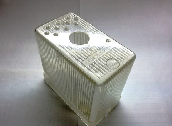
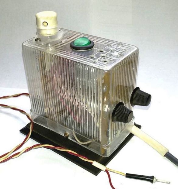
2. We select the housing to accommodate the parts of the device. We use a molded box from an old relay with dimensions of 100 x 60 x 95 mm.
3. We complete the device with parts in accordance with the scheme. We cut out the boards for the power unit and the control circuit in accordance with the dimensions of the housing used.
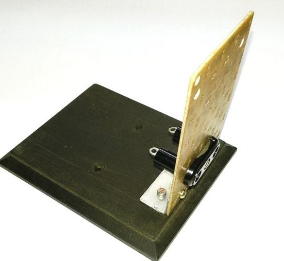
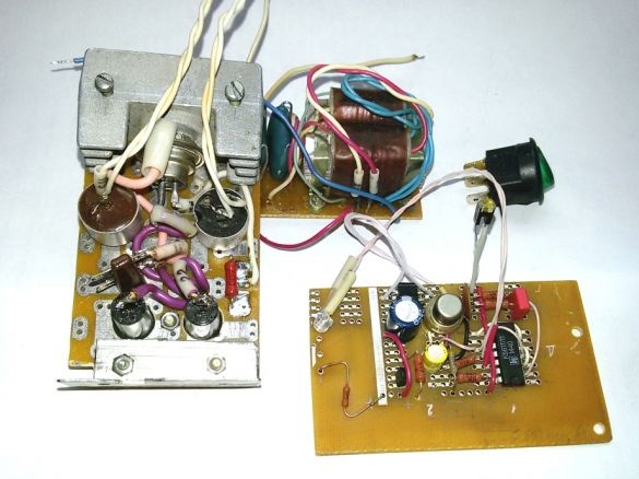
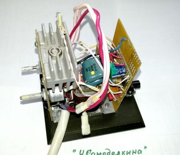
4. We make the base of the device from sheet plastic with a thickness of 6 ... 10 mm. We place on the base a board for the power part of the device circuit.
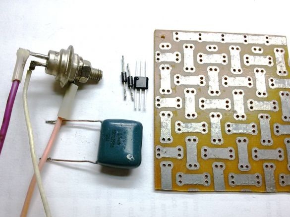
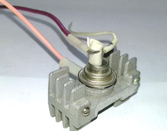
5. In the proposed device circuit, the switching element is the KU208G triac, which can control a load of up to 400 watts. With a load power of more than 200 W, the triac must be installed on the heat sink. We install the triac on the radiator and mount the power part of the device circuit on the board.
6. We assemble the parts of the control circuit on a universal circuit board. To control the operation of the circuit, in turn with the optocoupler LED, turn on the control red LED.
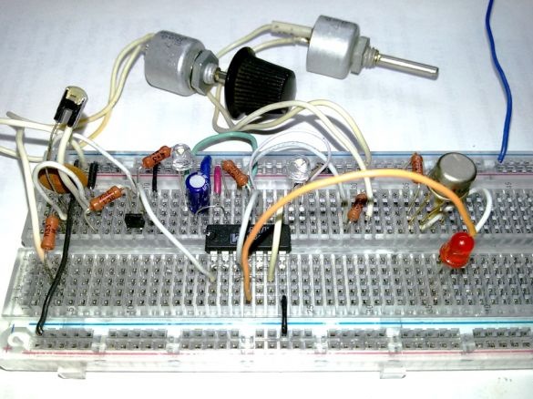
7. We check the operation of the control circuit powered by a transformer. When the photoresistor is hidden from the light, the control red LED lights up, and when opened, it goes out. Adjustment with a variable resistor changes the switching threshold.
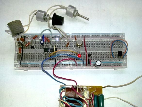
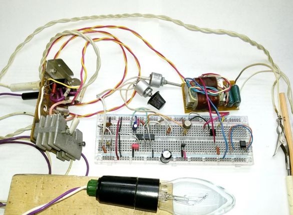
8. We collect and verify the operation of the device circuit as a whole. The load is a 60-watt lamp.
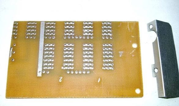
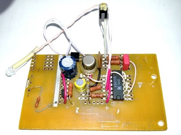
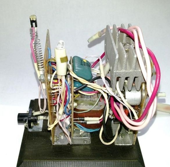
9. We transfer the details of the control circuit to the prepared mounting plate.
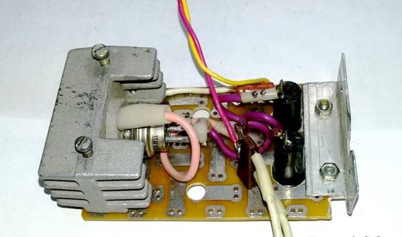
10. We complete the device with assembled circuit boards, a power supply unit, a power switch and a connector for connecting a humidity sensor. We collect all the nodes on the base of the device.
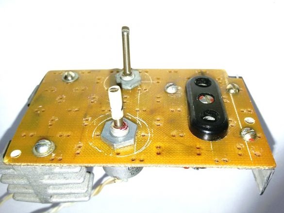
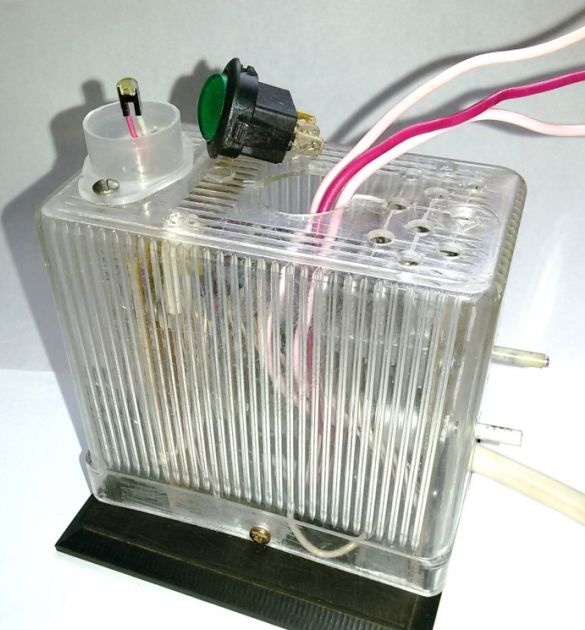
11. We are finalizing the device case. We carry out the necessary holes - for cooling the triac radiator, power switch, connector and humidity indicator, tuning regulators, a socket for connecting the load.
12. Finally we assemble and test the device.
The duration of artificial illumination will depend directly on natural light. Perhaps this is a couple of hours in the morning and a few hours in the evening. In general, this time will be approximately 5-7 hours. 4 hours are enough on a sunny day, and up to 10 hours on a cloudy day.
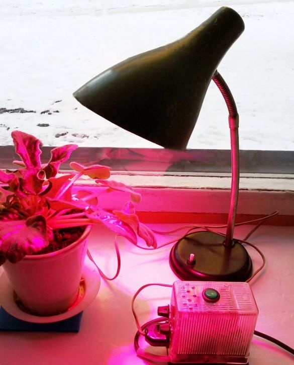
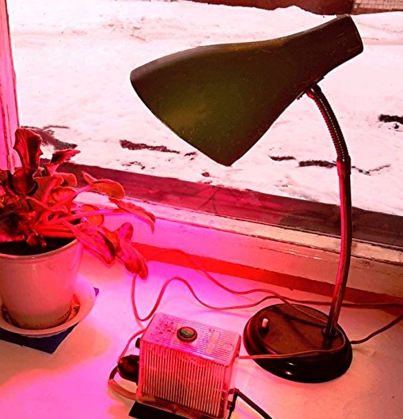
The proposed device, turned on in the morning, during the day will automatically maintain the optimal level of illumination, turning on or off artificial lighting depending on the weather outside.
An important process in organizing lighting is the selection of suitable lamps.
Seedlings can be grown using white fluorescent lights, they create cold light (their spectrum is as close as possible to the solar spectrum). Since these lamps are not very powerful, they are installed simultaneously in several pieces in special reflectors that enhance the flow of light.
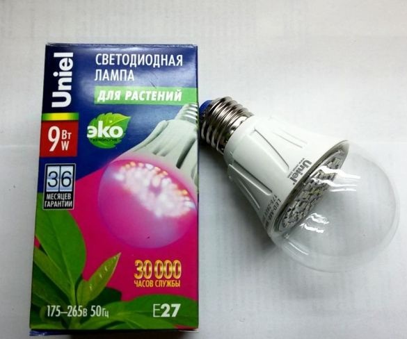
Phytolamps with several peaks of light emission in the blue and red spectrum are excellent for growing seedlings. Phytolamps have a full spectrum of rays required only by colors, but create light that irritates a person’s vision. It is for this reason that phytolamps especially need reflectors.
Well-established in home LED lamp conditions. Such lamps do not heat up; they are economical and durable. An alternative may be modern LED lamps, the cost of which is quite high, however, it is justified by low consumption and a long resource. Such lamps combine two very important spectra - red and blue. In addition, LED lamps consume a small amount of electricity, their cost pays off in a short time. These lamps are easy to install and easy to operate.