

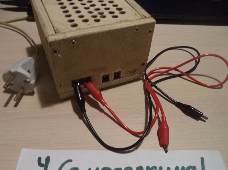
I welcome all visitors to the site and who decided to look at my article. Electricity today is the most important element of our life. All devices now work on electricity, whether it’s at least household, computing ... Our life is almost difficult to imagine without wires, batteries, sockets. But each of these devices is powered by its own voltage: at five volts, twelve ... Therefore, since there are not a few devices, a certain voltage is required for each of them. For example, a 220V refrigerator cannot be connected to the laptop’s usb port, it will be ridiculous, since five volts is very small for a refrigerator. Well, you can’t connect the phone directly without a special device to a 220 V socket, otherwise the phone will simply burn out. And so that the phone does not burn out, for this there are special power supplies that convert the high voltage to a lower one, for example, a twelve volt power supply. With such a favorable voltage, for example, an LED strip will work, that is, from twelve volts. It is in this article that you will see and learn (if you still do not know) how do it yourself to make the simplest power supply from improvised materials. In my case, the power supply will give out 17 V. In my power supply there will be two connectors for connecting and a place where mounts like crocodiles will be attached. To make this homemade we will need:
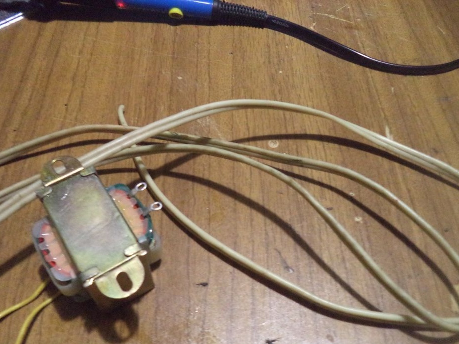
1. Step-down transformer with an input voltage of 220 V and an output of 10 V AC;
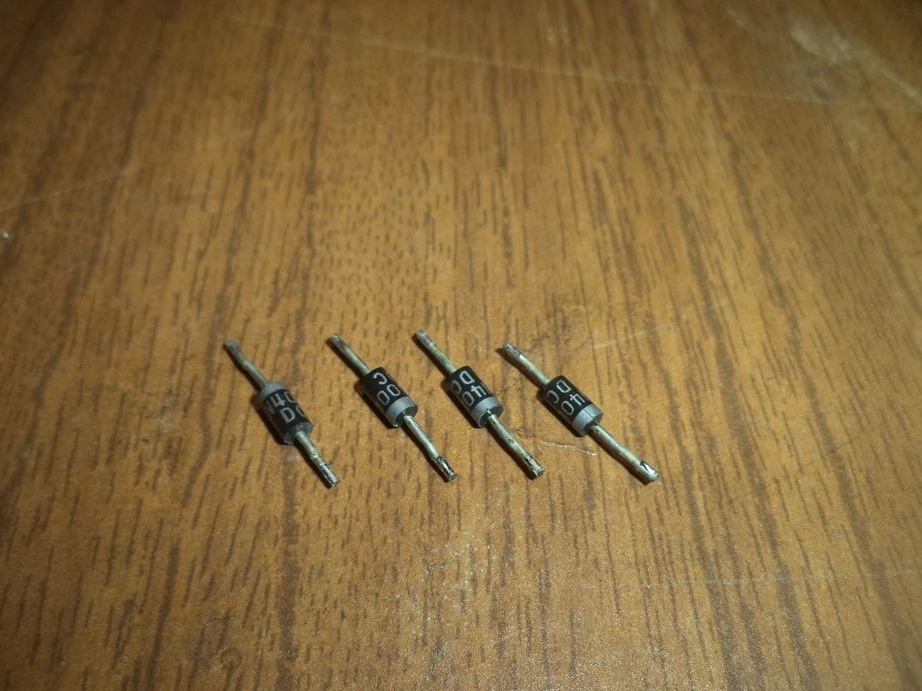
2. Four diodes for the manufacture of a rectifier diode bridge, which converts alternating current into direct current, that is, the current which has "+" and "-";
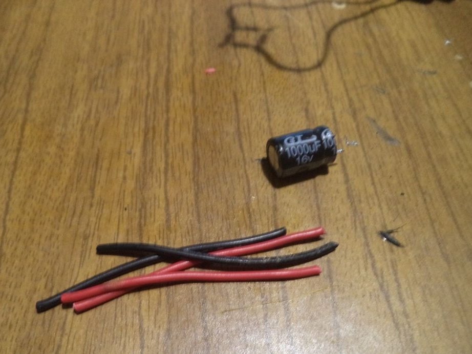
3. A capacitor designed to smooth DC oscillations after the rectifier;
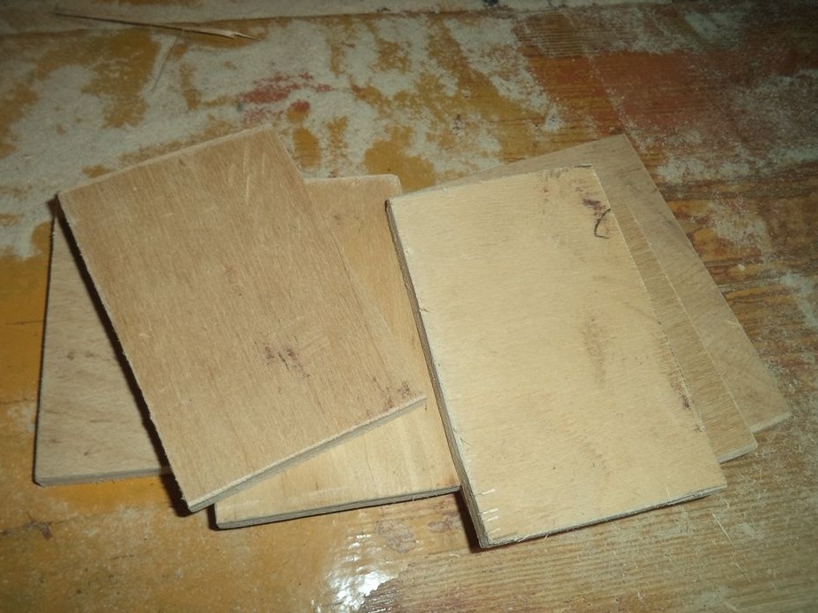
4. Plywood of any thickness, designed for the manufacture of power supply housing;
5. Heat shrink tubing to isolate exposed areas;
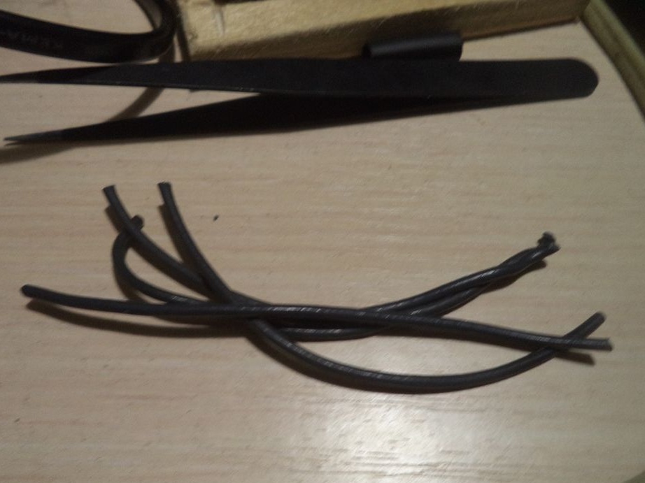
6. A coil of wires;
7. An electric plug for connecting the device to a 220 V network;
8. CD disk for the manufacture of the housing of some parts;
9. Insulating tape;
10. Copper wire with a thickness of 3 mm;
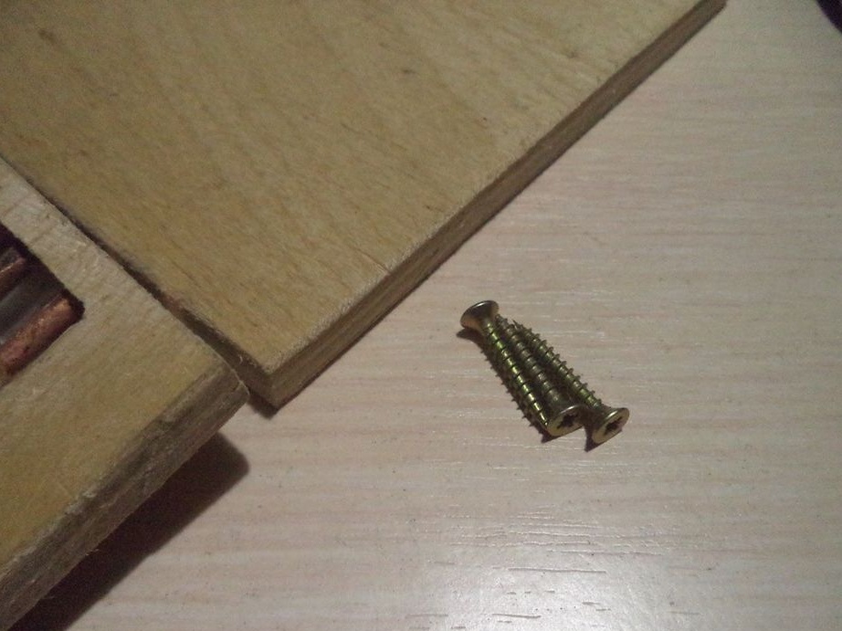
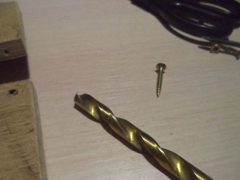
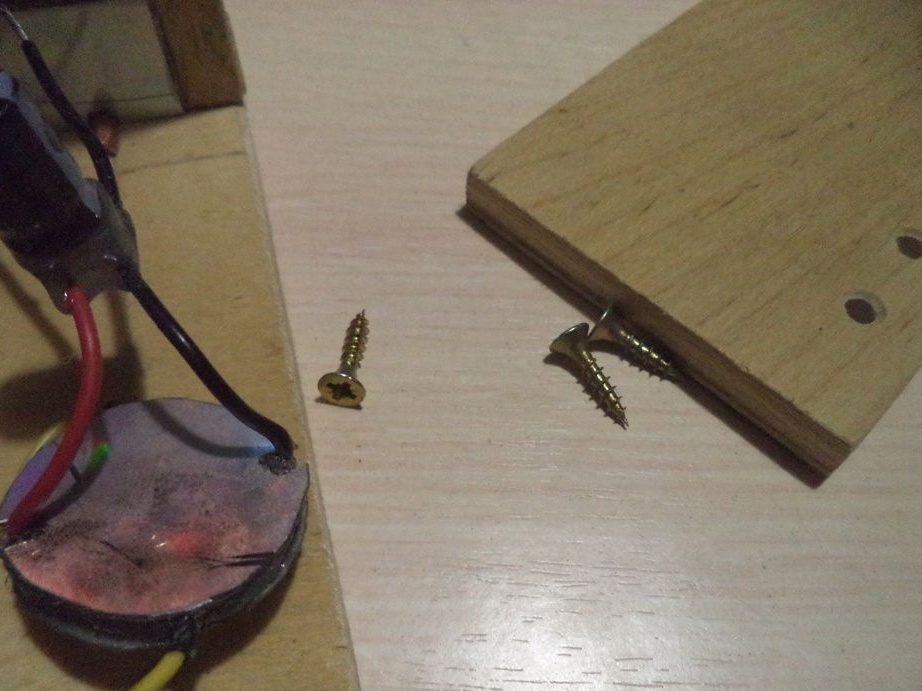
11. Self-tapping screws for assembling the wooden case of the power supply;
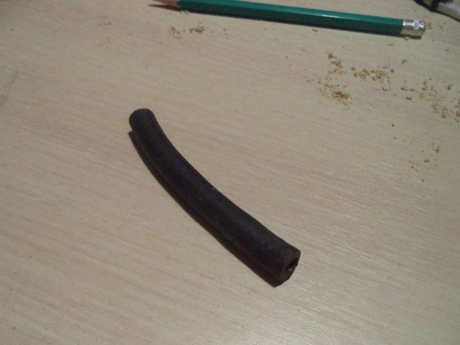
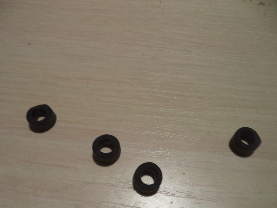
12. Rubber tube for the legs of the power supply;
13. Special connectors (2 pcs.) For connecting to the power supply.
1. Electric soldering iron for soldering contacts;
2.Tweezers for easier work with small parts;
3. Stationery knife for cleaning wires from insulation and other needs;
4. Screwdriver for unscrewing screws;
5. Scissors for cutting wires;
6. A multimeter for checking indications of a future power supply unit;
7. Glue gun and hot melt adhesive for gluing some parts or for insulation;
8. A simple pencil for drawings on plywood;
9. Square and ruler for making measurements;
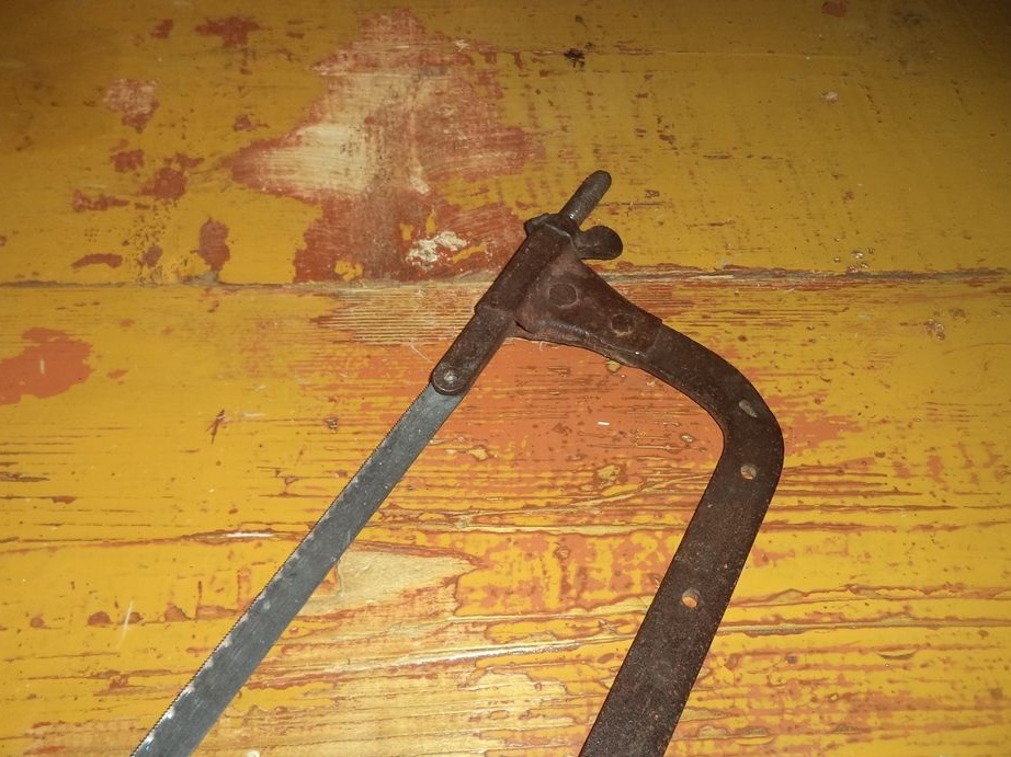
10. Metal cutting for cutting plywood, as the edges of the plywood will crack;
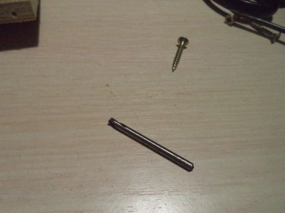
11. A drill and a disk for cutting wood to cut some parts (it is difficult to cut plywood with this disk);
12. Chisel for making recesses on plywood;
13. Sandpaper for straightening uneven surfaces;
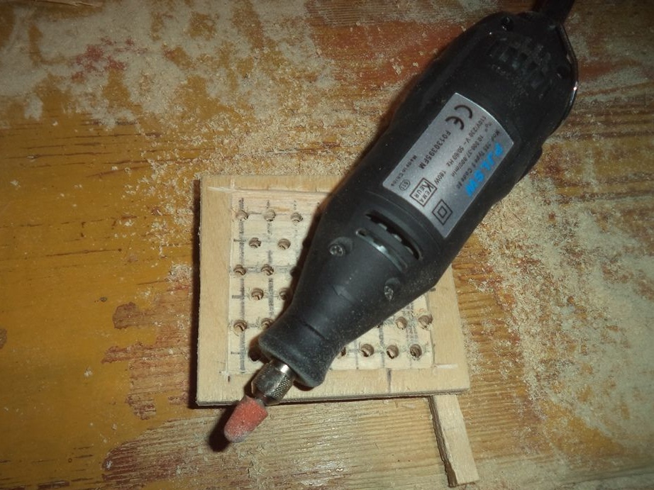
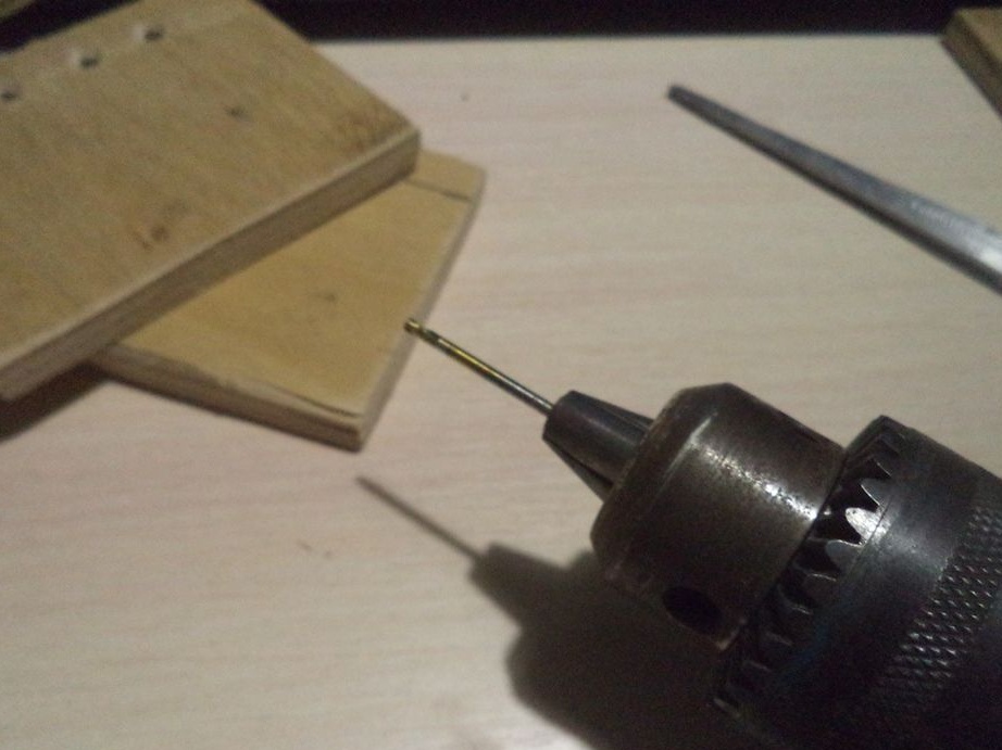
14. Electric drill and drill of different diameters for drilling holes;
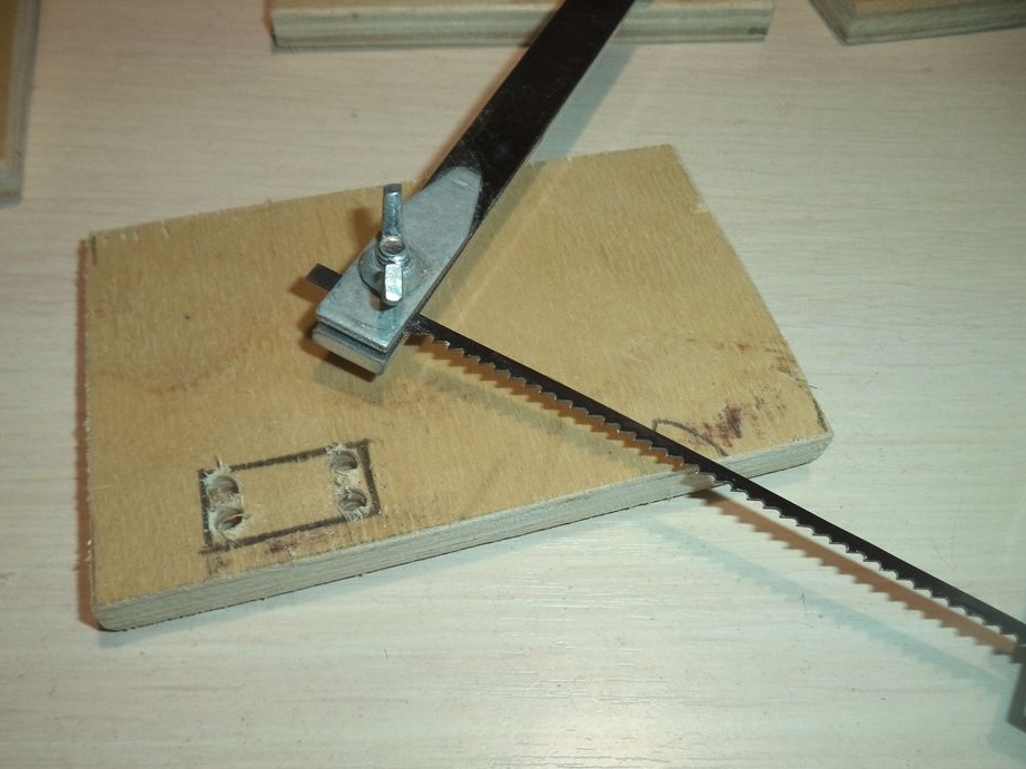
15. Jigsaw for cutting square or rectangular holes;
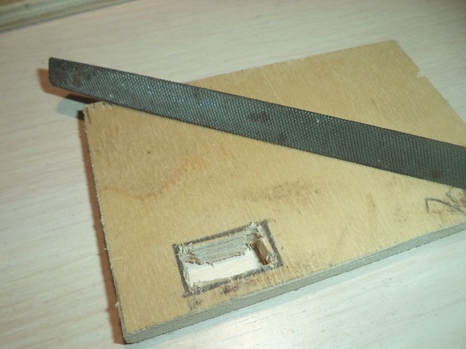
16. File for aligning rectangular holes;
17. Superglue for gluing small parts;
18. Markers black and red to indicate plus and minus on the power supply;
19. Lighter for shrink tubing.
The process of manufacturing a power supply.
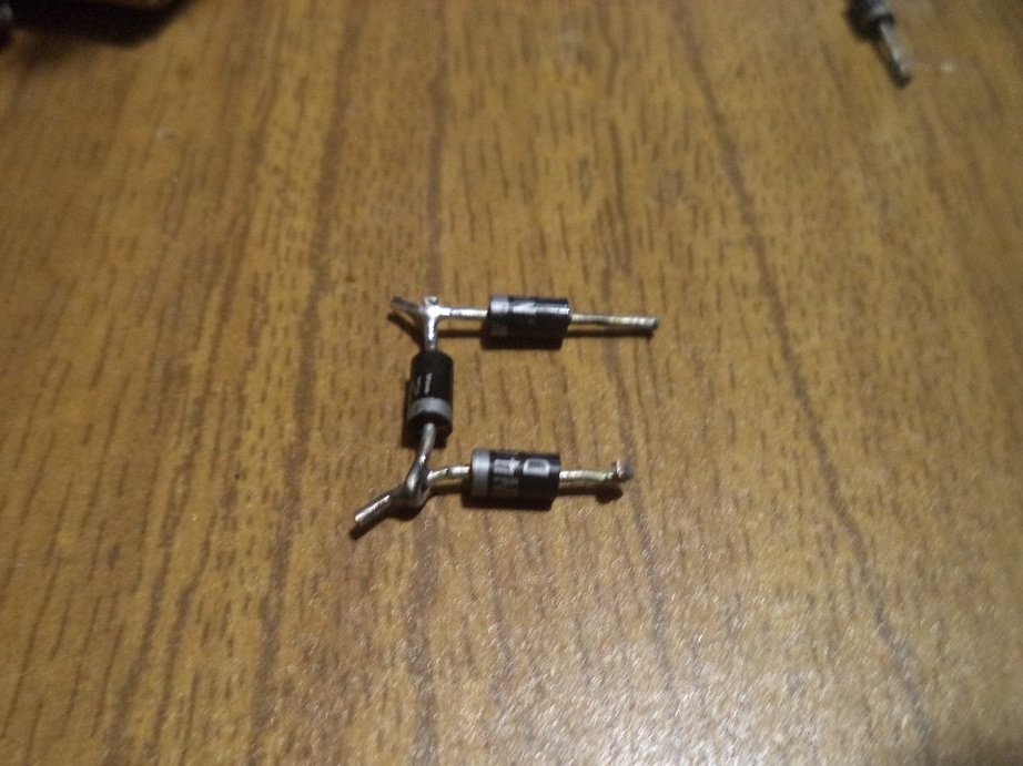
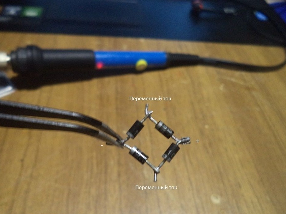
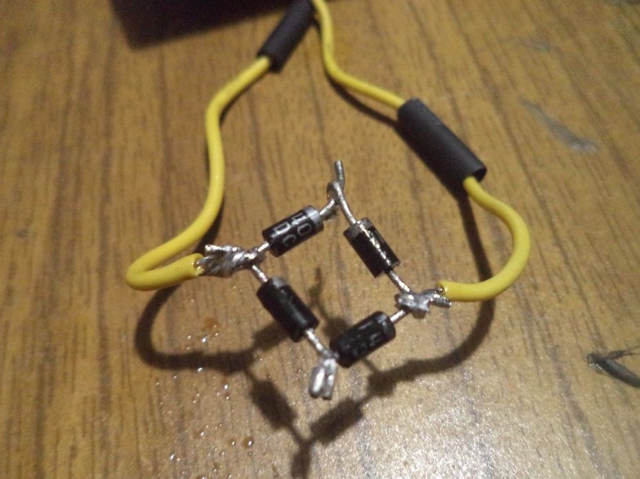
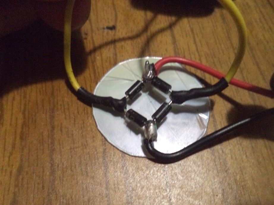
In the beginning, we take four diodes and assemble from them a diode bridge that will convert alternating current to direct, as I mentioned earlier.
Using an electric soldering iron, we solder one of these four diodes.
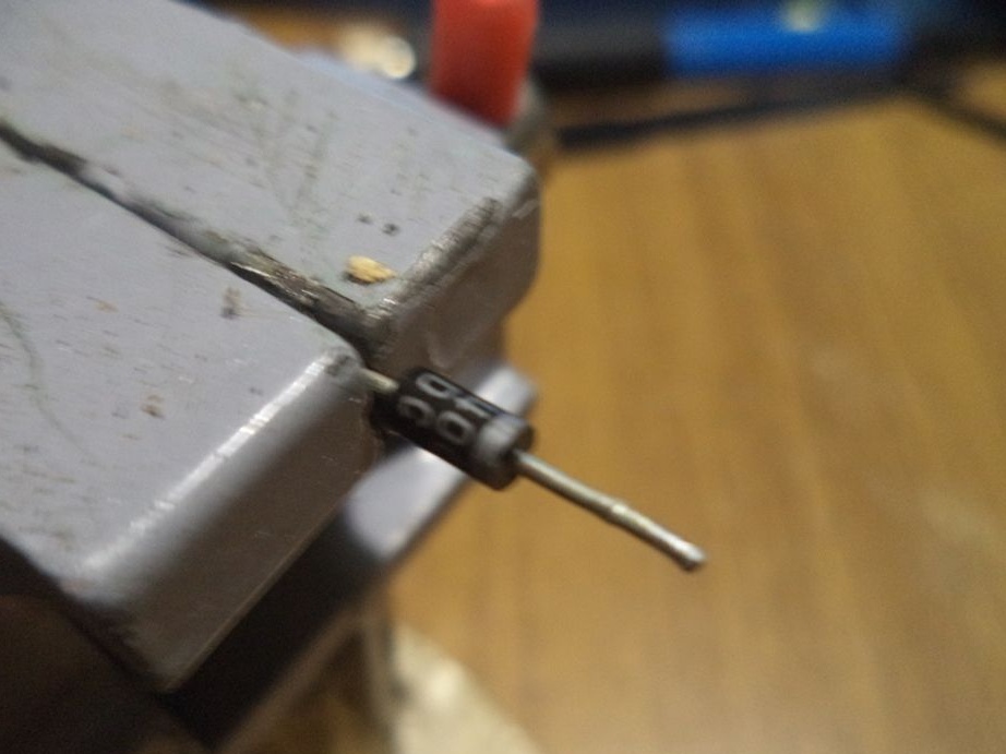
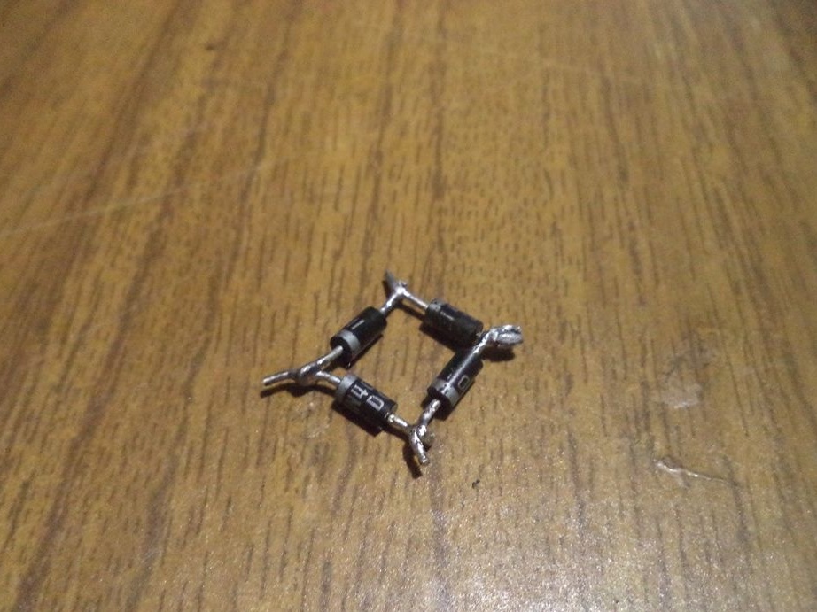
This is what the contacts of the diode post mean:
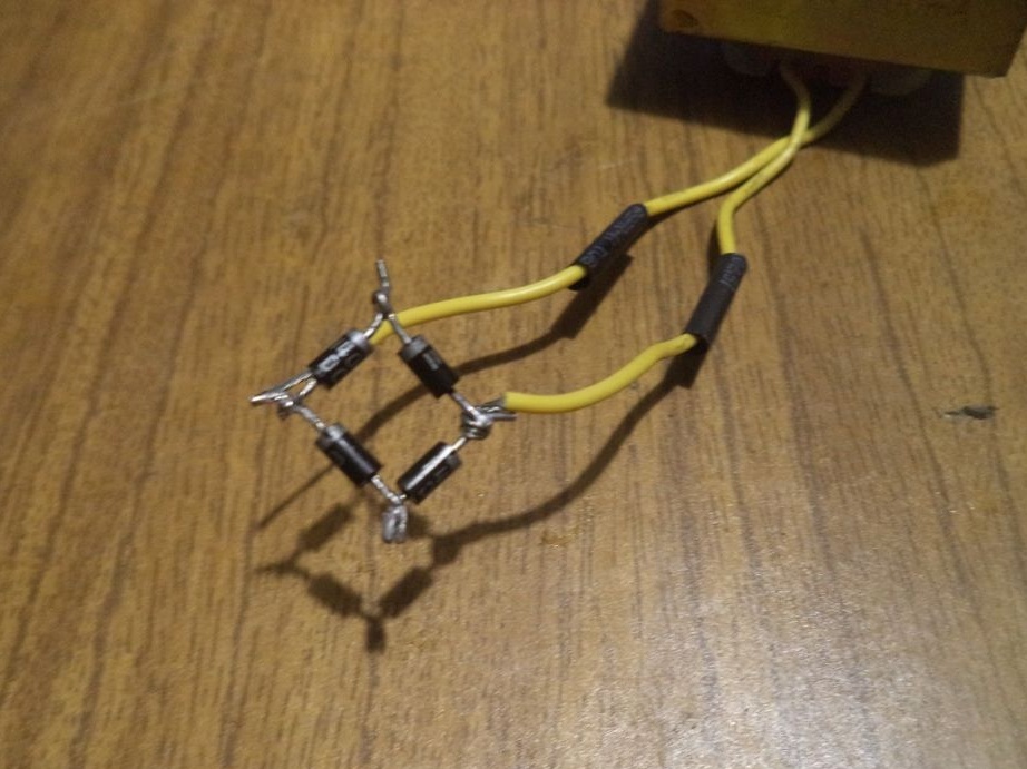
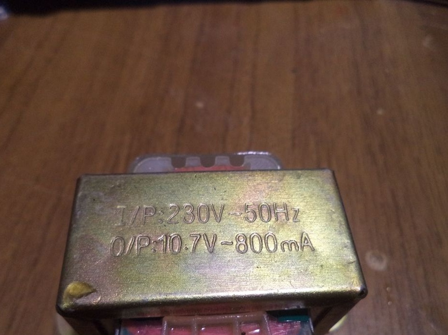
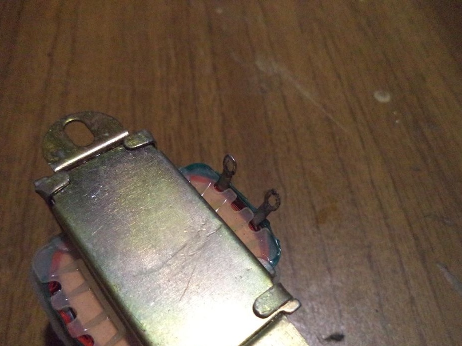
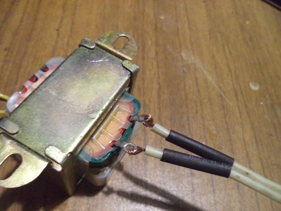
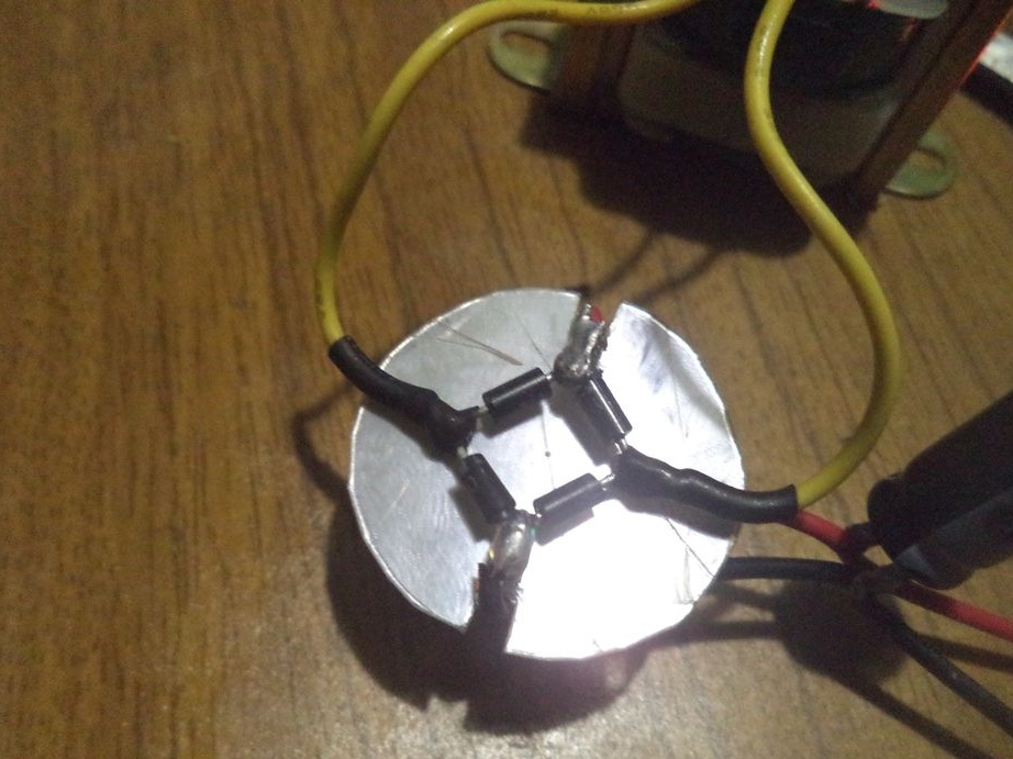
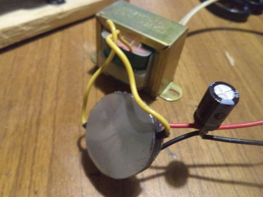
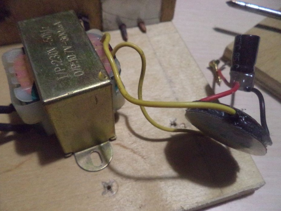
Now we solder the diode bridge to the step-down voltage transformer.
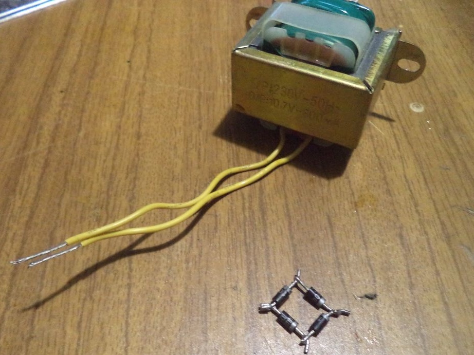
By the way, the characteristics of a step-down voltage transformer:
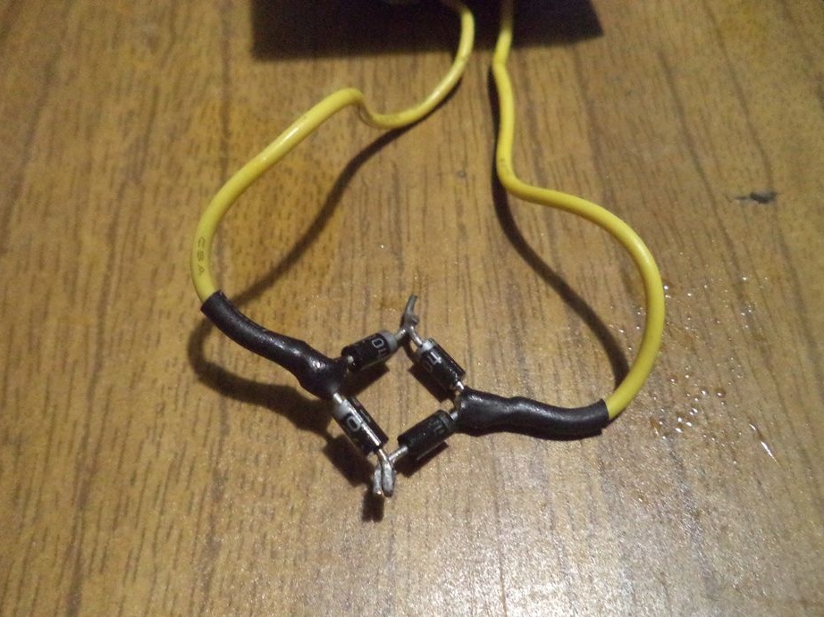
Next, we isolate the soldered sections from the transformer and the diode bridge using a lighter and heat-shrink tubing.
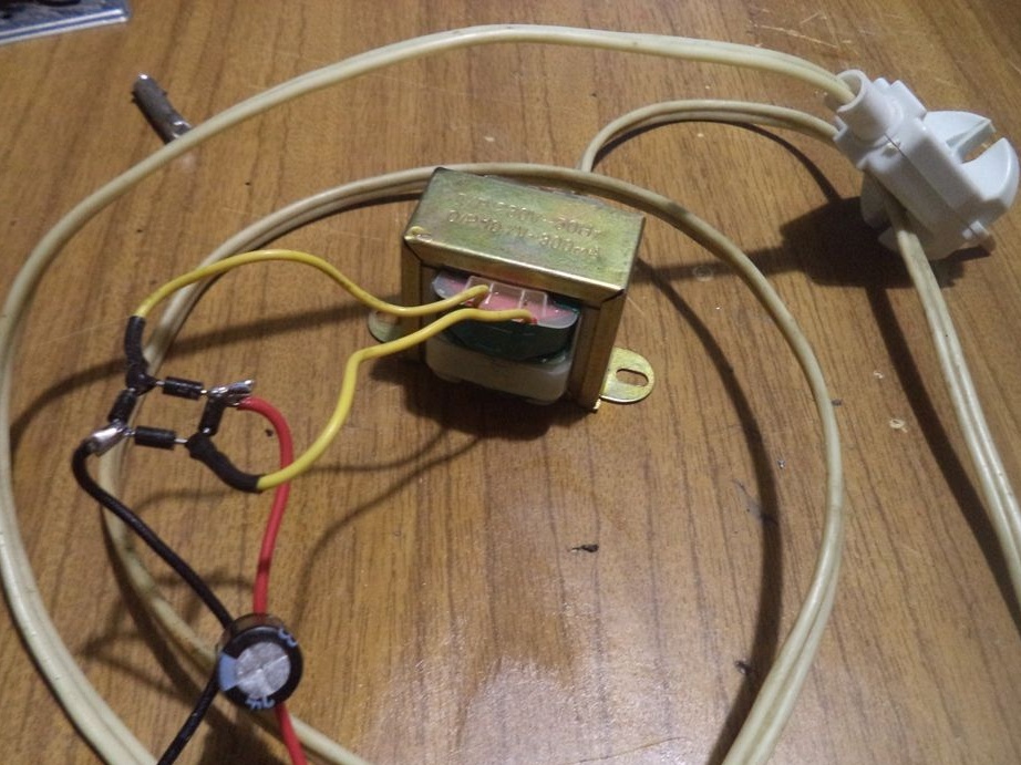
Now we solder a wire to the step-down voltage transformer, with which the transformer will be connected to a 220 volt network.
To do this, I took the wire from the old lamp.
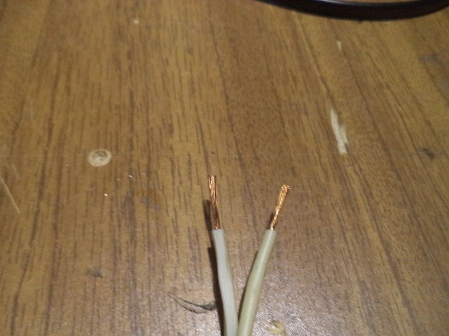
We clean the contacts, put on the heat shrink and solder the wires to the transformer.
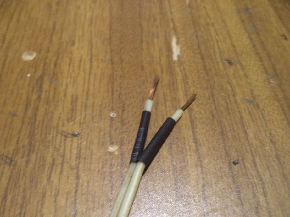
Isolate the wires.
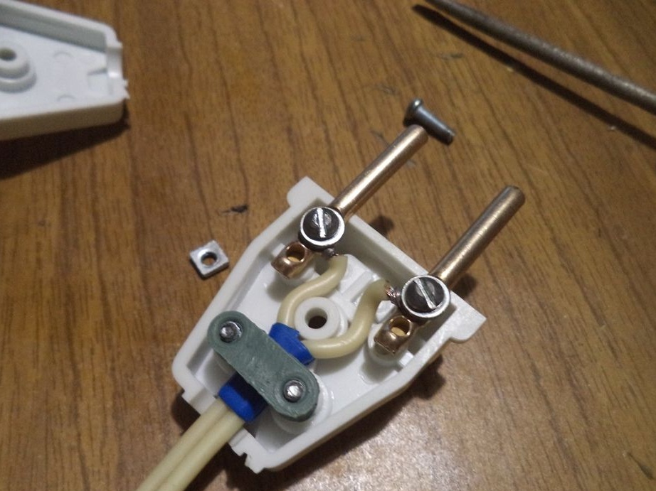
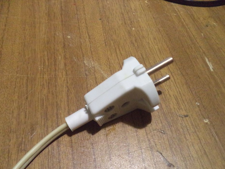
On the other end of the wire we connect an electric plug, purchased at an electrical store.
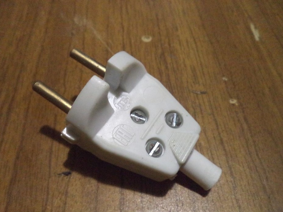
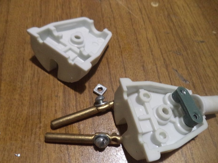
Do not forget to put on a part of an electric plug earlier. Screw the wires to the plug terminals and assemble the case back.
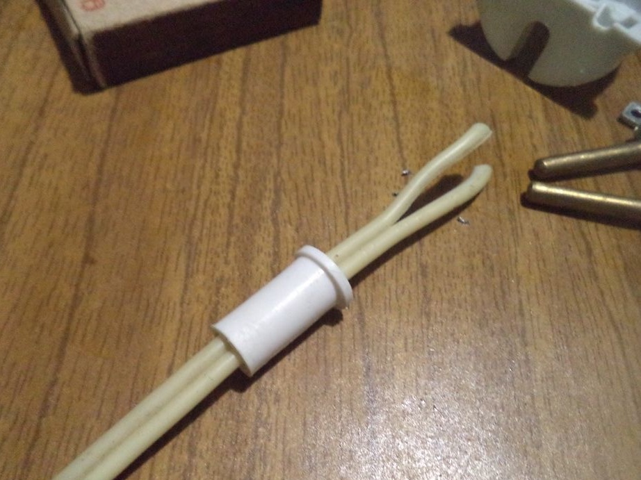
Since the wire did not hold on to the fastening of the plug, we wind it with electrical tape.
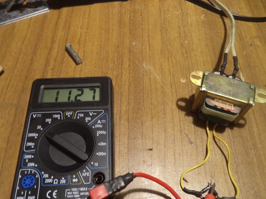
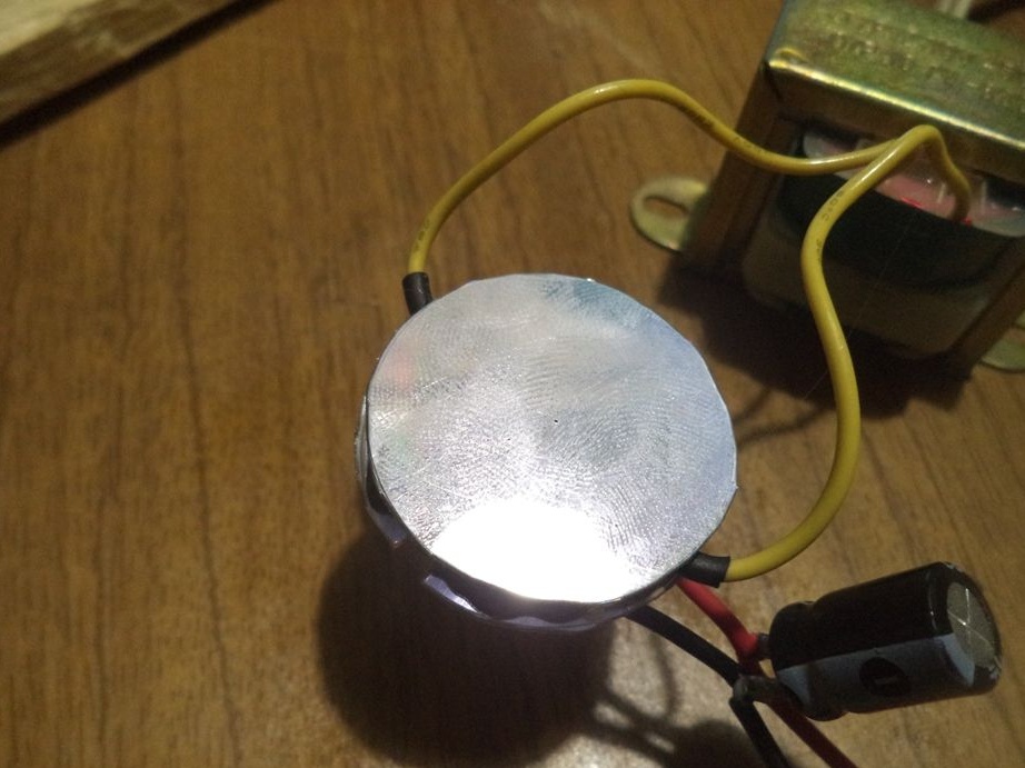
Check the readings of the resulting circuit with a multimeter. As you can see, the voltage is issued while 11.27 volts. Further, the readings will still change.
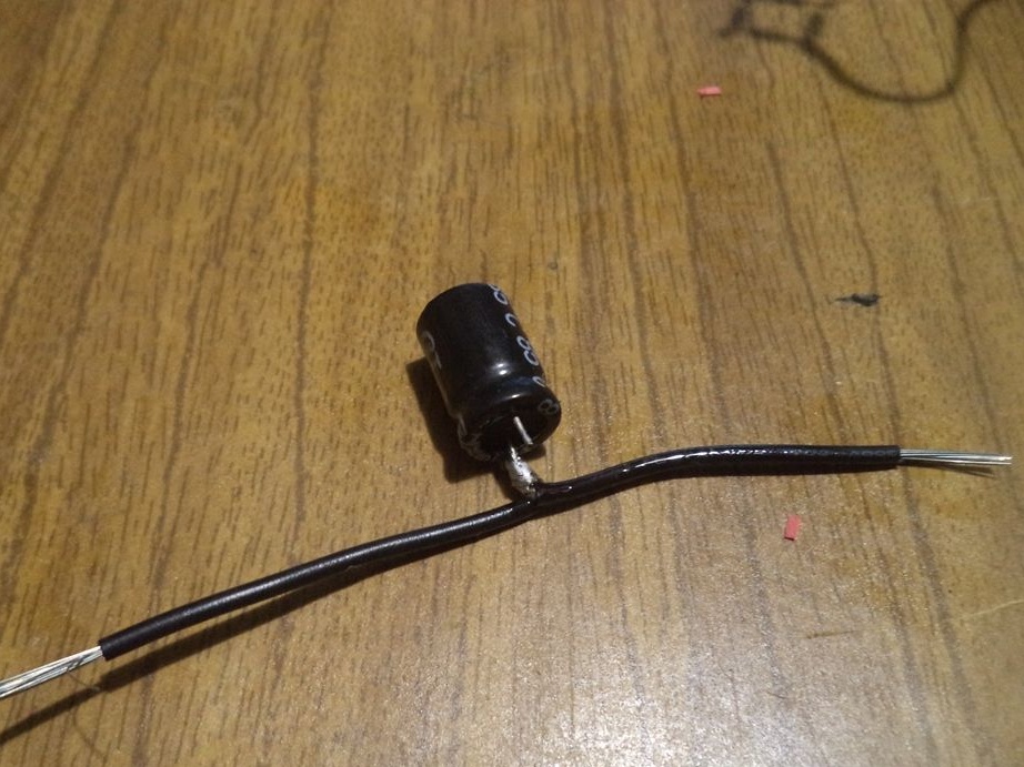
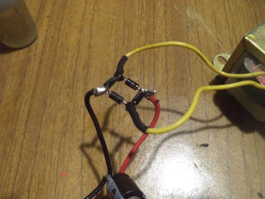
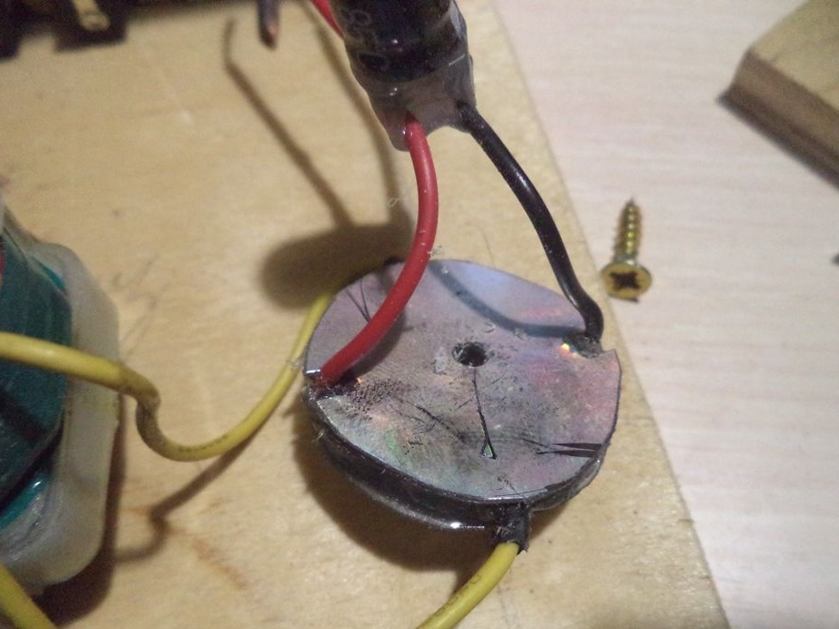
Now, to the plus and minus of the rectifier diode bridge, observing the polarity, we solder the capacitor, which will smooth out the voltage fluctuations of the post diode bridge.
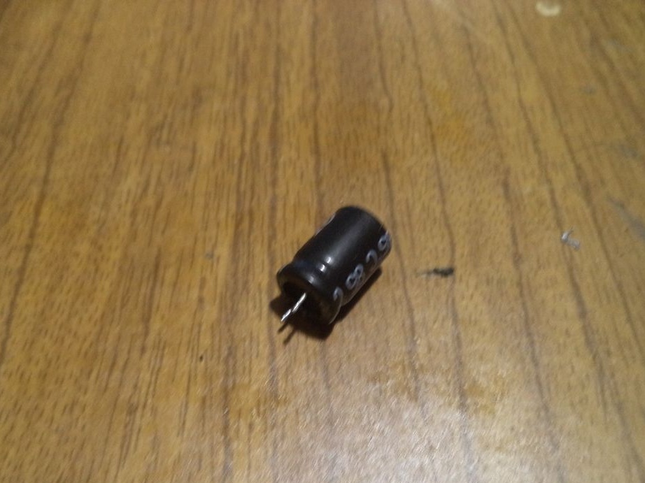
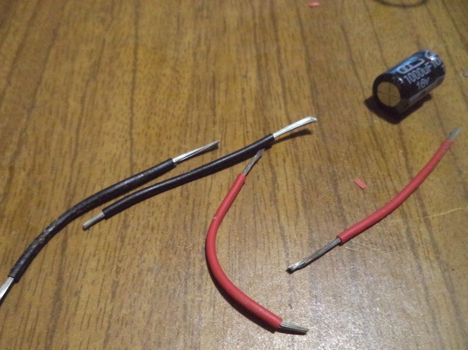
To do this, we need black and red wiring, since the capacitor contacts are small to solder to the bridge.
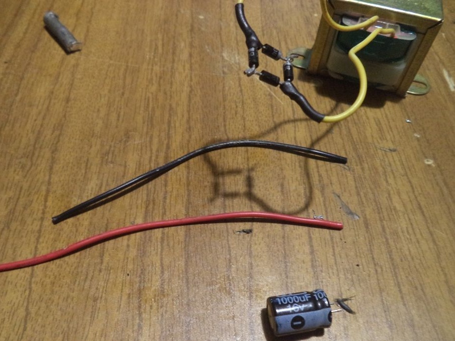
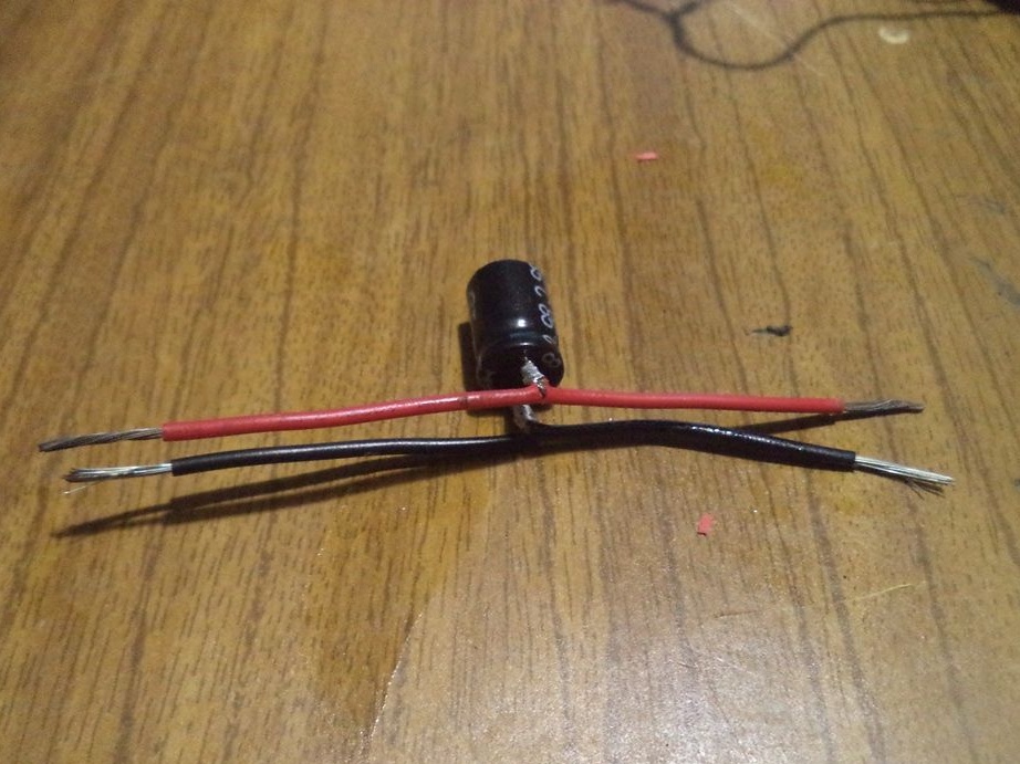
After soldering the capacitor, the voltage at the terminals increased to 16.88 volts.
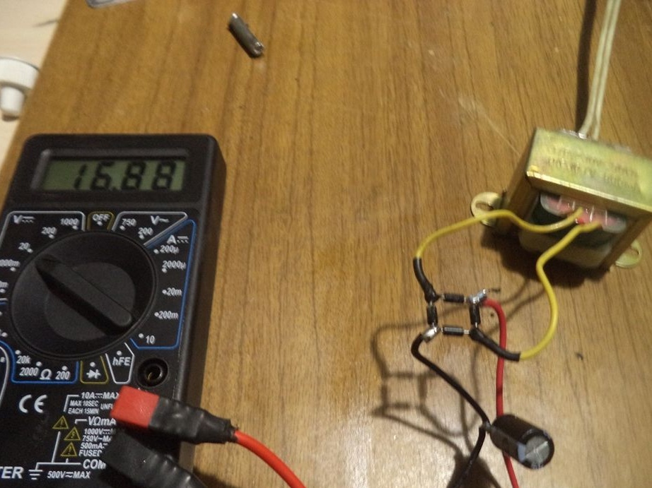
This is the electrical circuit we have.
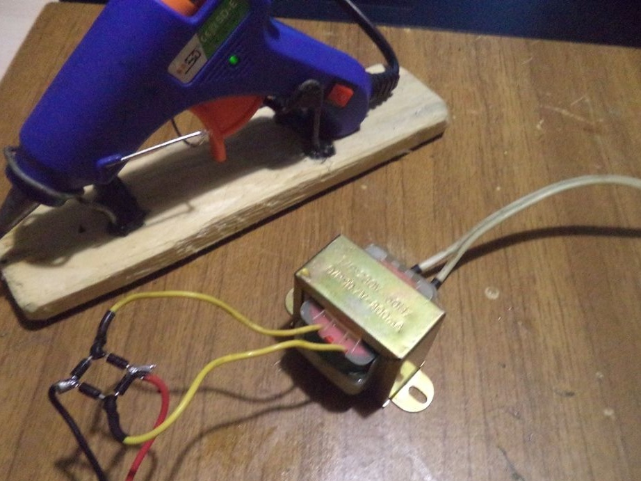
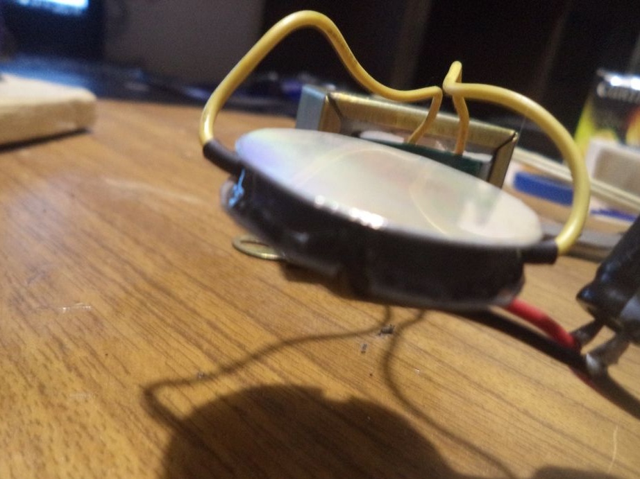
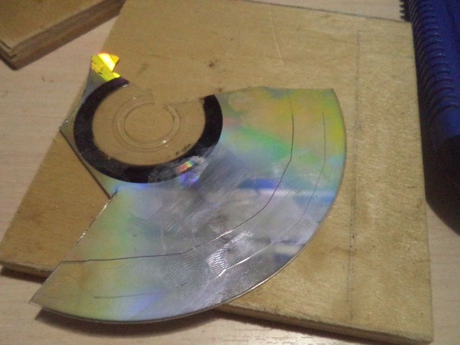
Now we will make the case for the diode bridge from a regular CD disc and gluing everything with a glue gun.
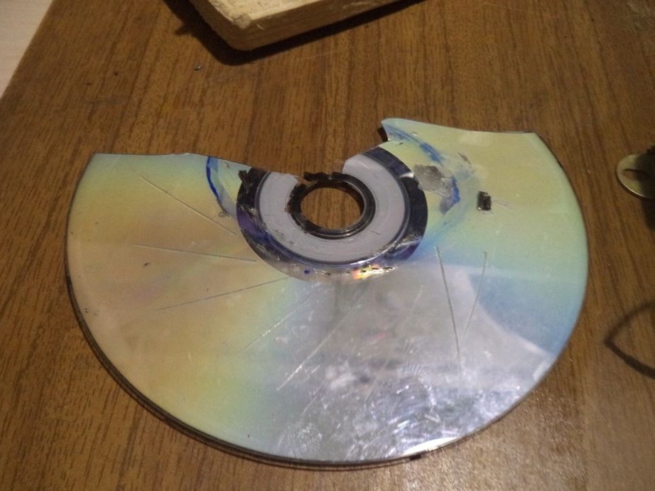
Using a stationery knife, divide the CD into two parts.
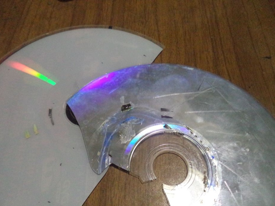
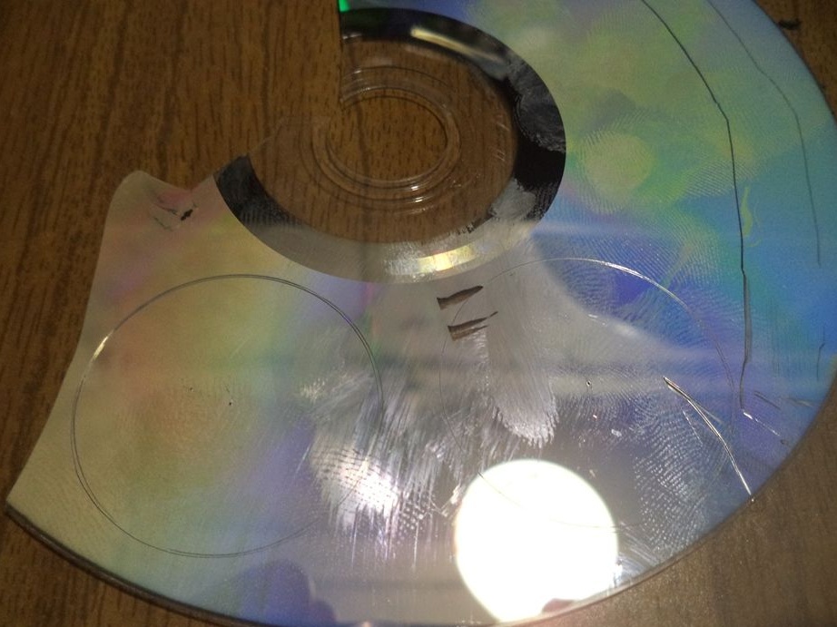
From one of the parts we cut out two identical circles.
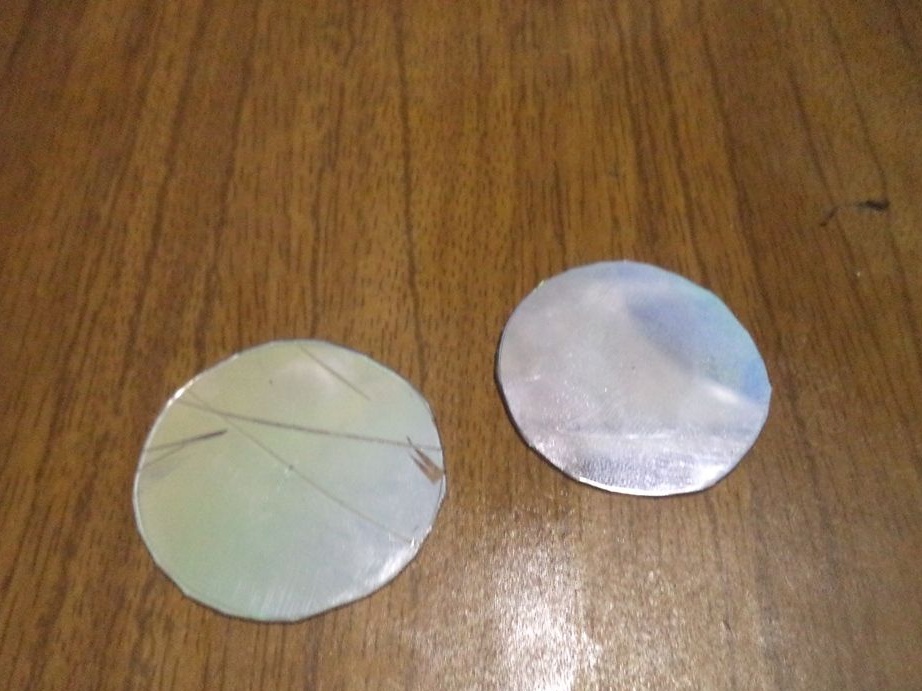
Now from them we glue the case for the diode bridge as follows.
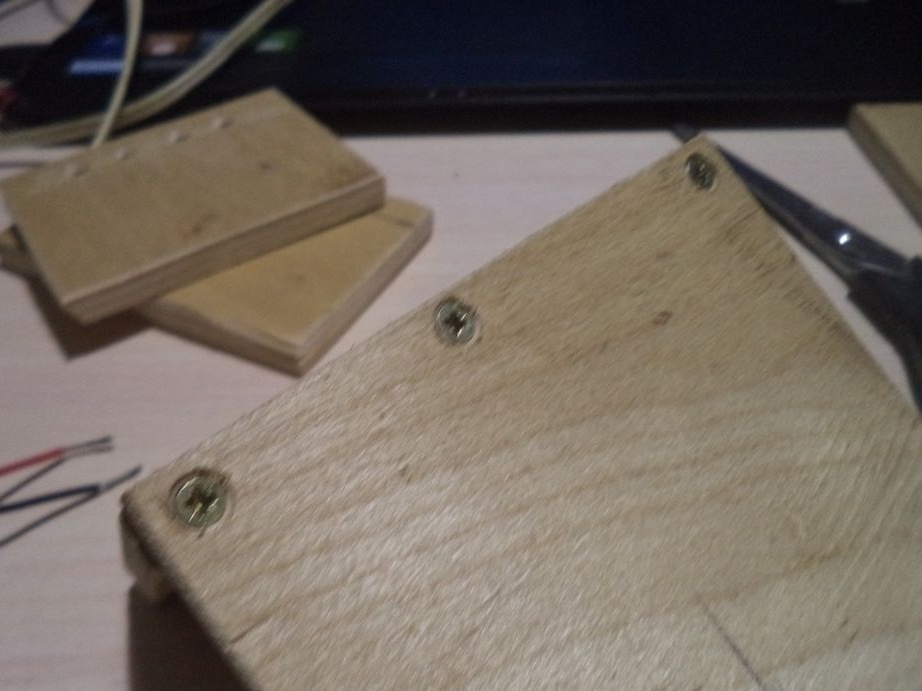
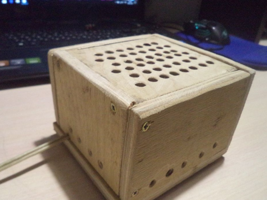
Everything, the main thing, that is, the electric circuit, is ready, now you need to assemble a wooden case, which is the most difficult in this homemade product. It took me just an hour or less to solder this chain, but it took me almost a day to complete the wooden case.
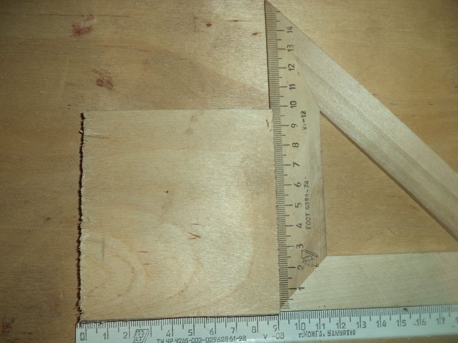
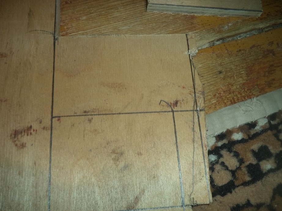
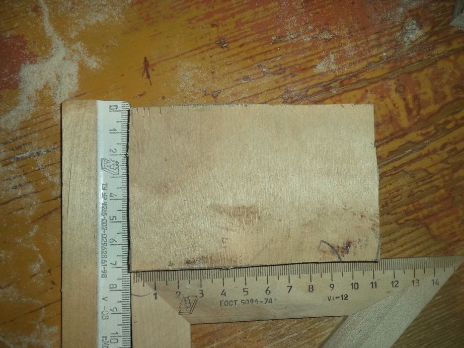
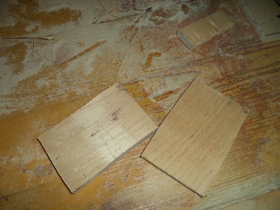
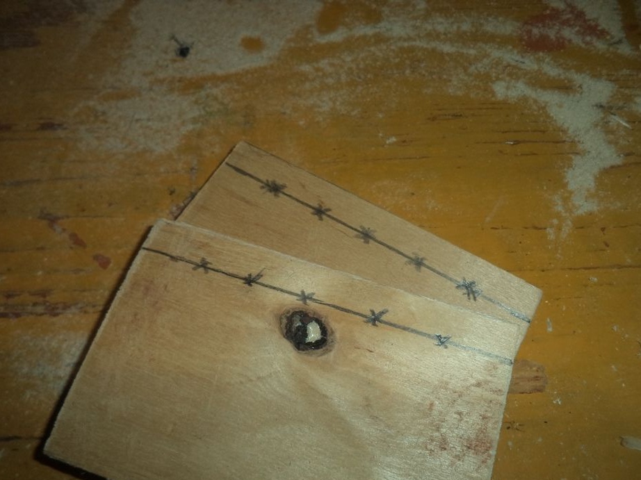
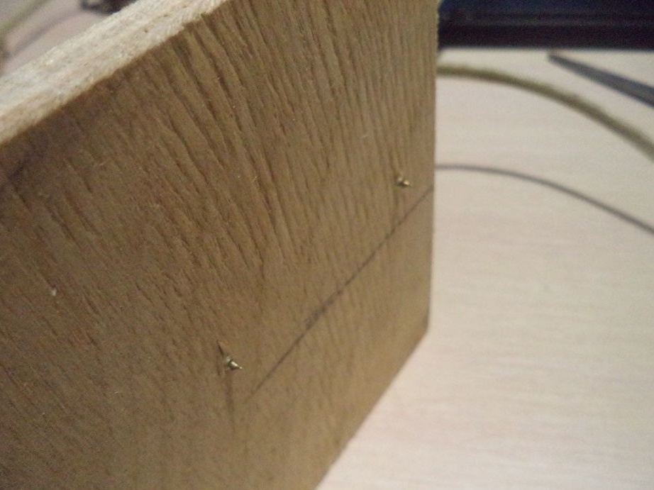
Now we take a simple pencil and a square and draw the details of the case on plywood and cut them out.
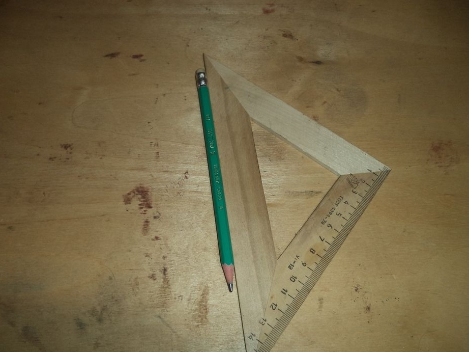
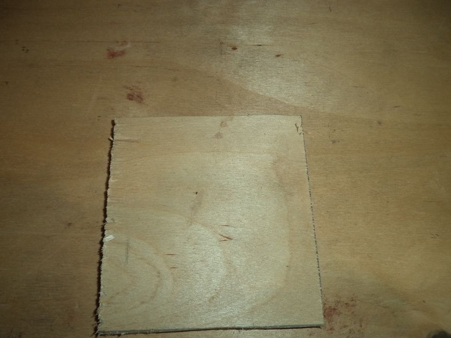
First, draw such a rectangle.
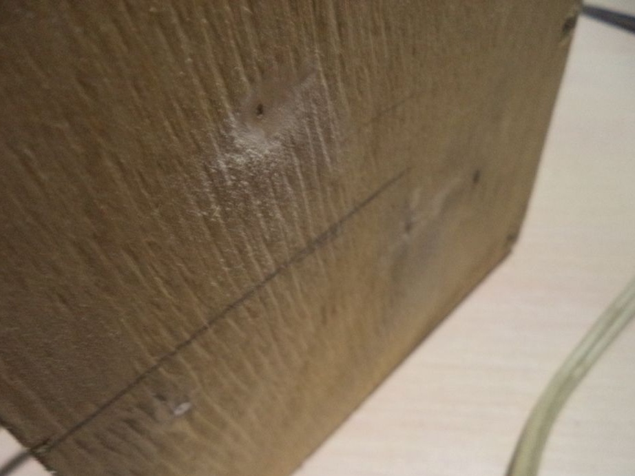
Next, using metal cutting, we cut this square. Why with the help of metal cutting, because with the help of a conventional hacksaw, the edges of the plywood crack, but with the help of metal cutting it is not.
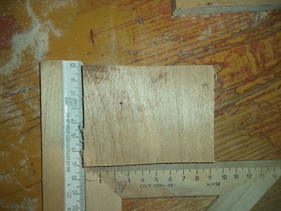
Now draw a rectangle a little bigger.
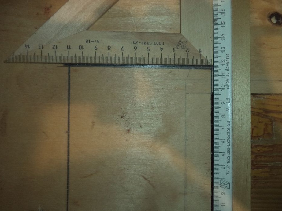
We also cut it with a metal cutting machine.
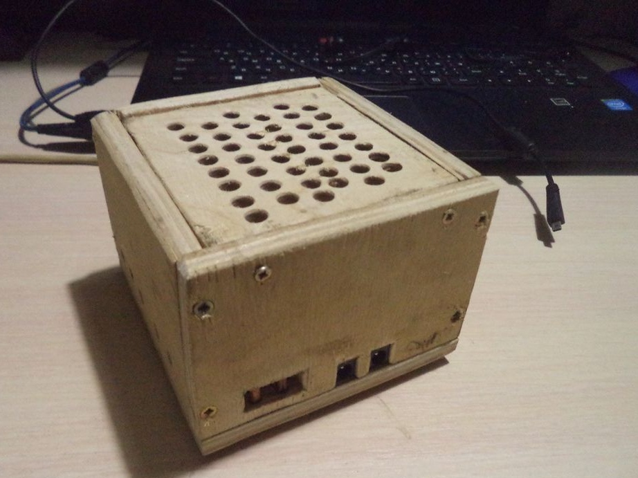
On a small rectangle we make a place for the cooling fan of the power supply. To do this, with the help of a drill and the circular disk intended for it, make the following slots.
We pick out with the help of a chisel a recess on a small rectangle with slots inside.
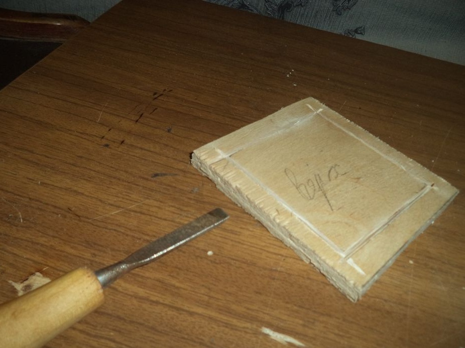
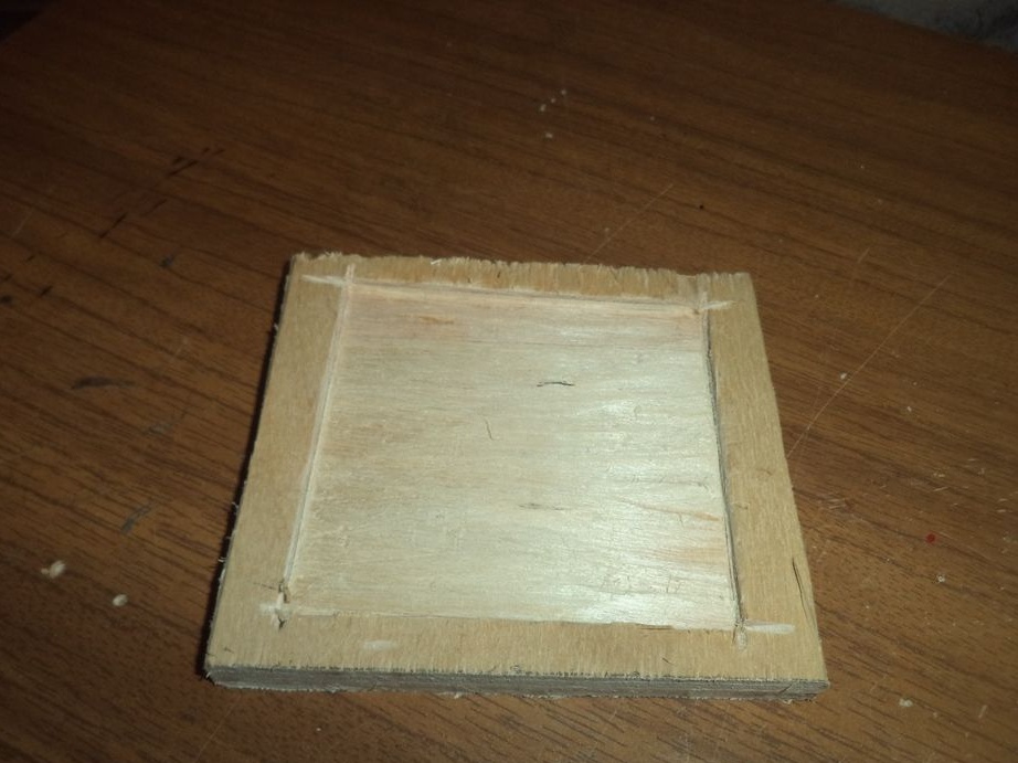
This will be the fan seat, which I don’t have yet. Therefore, so far the power supply will be without a fan.
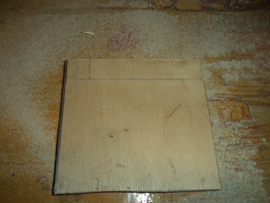
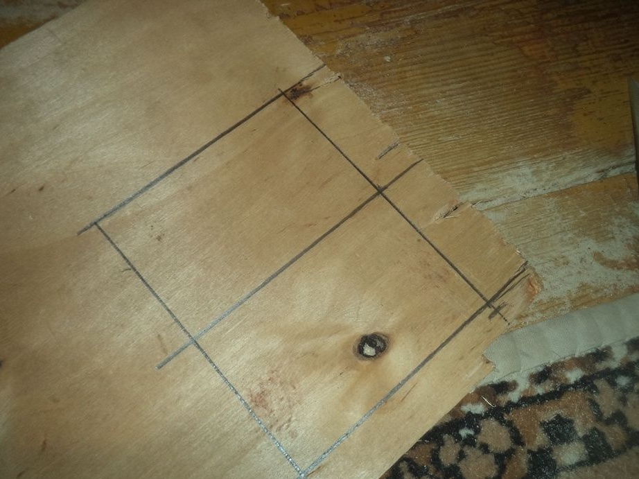
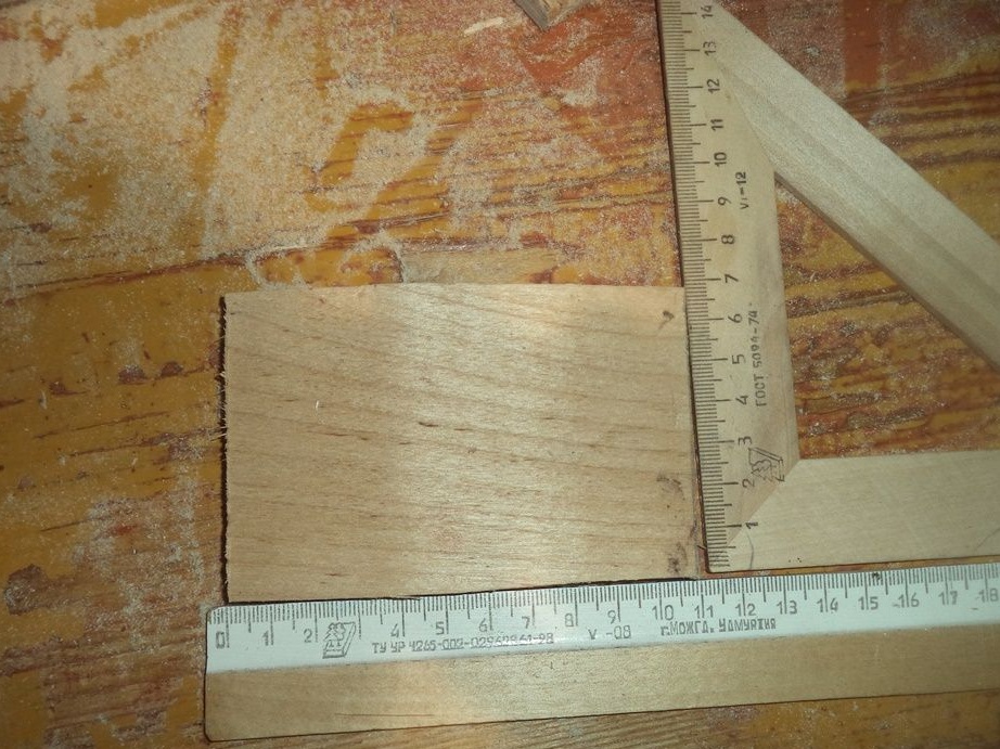
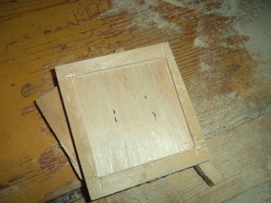
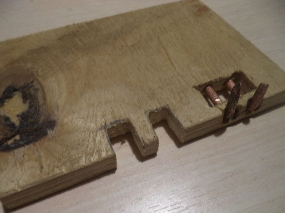
Now draw the following rectangles on plywood. one of them will be smaller. Next, we cut them.
Here are their places on the power supply housing.
And here are their sizes:
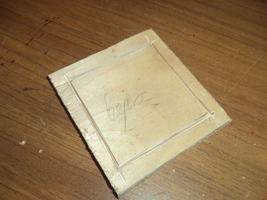
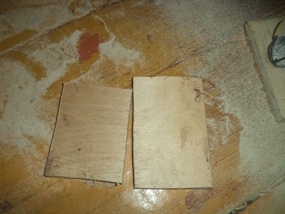
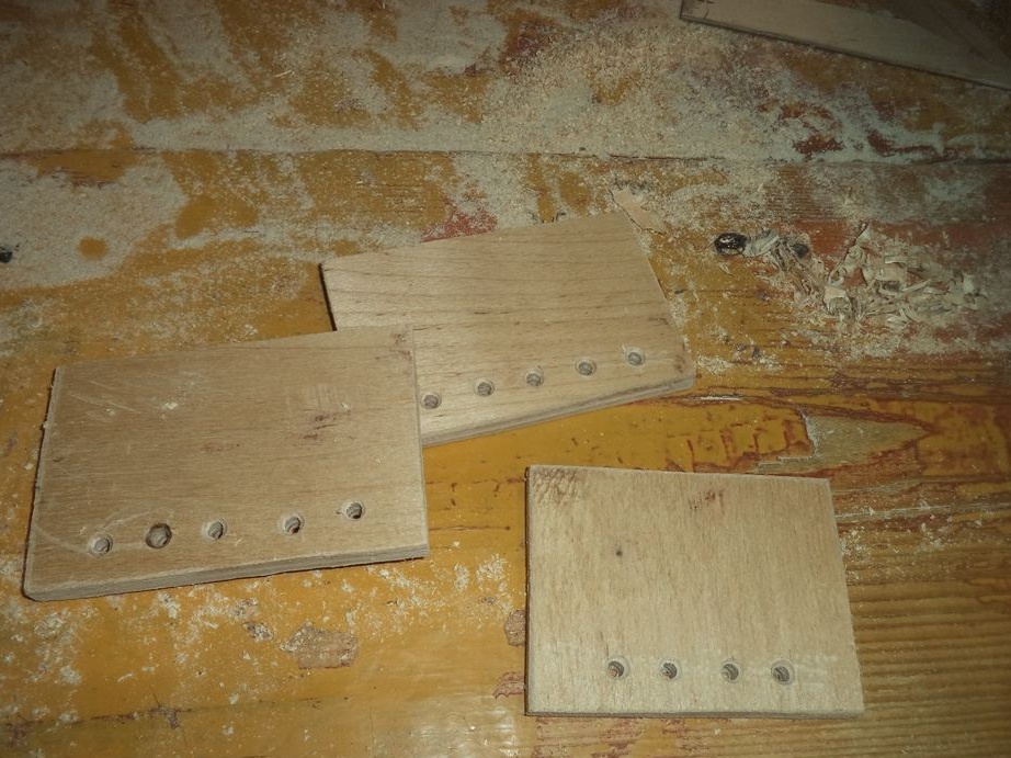
Next, we cut out the following two identical parts from plywood.
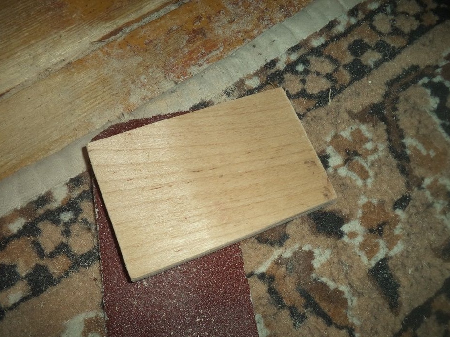
Now we process them with sandpaper.
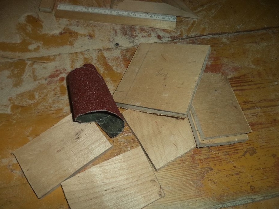
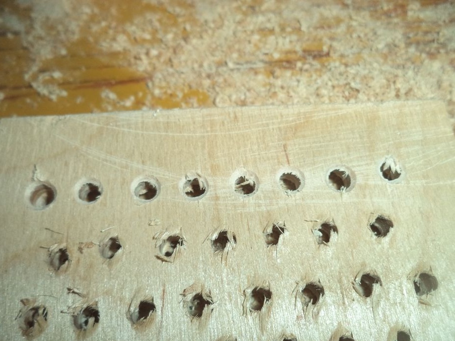
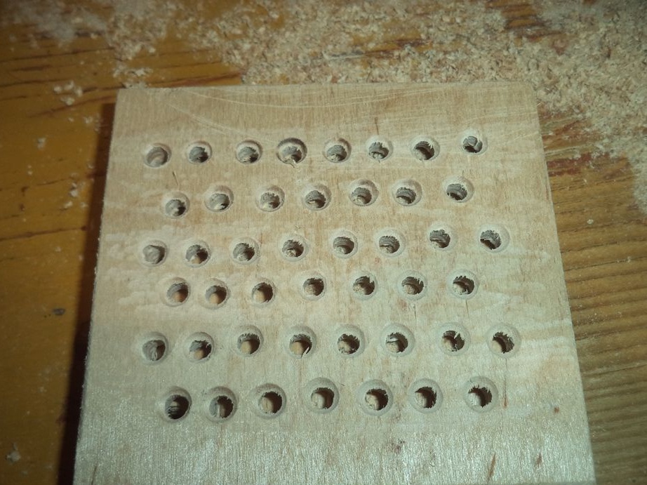
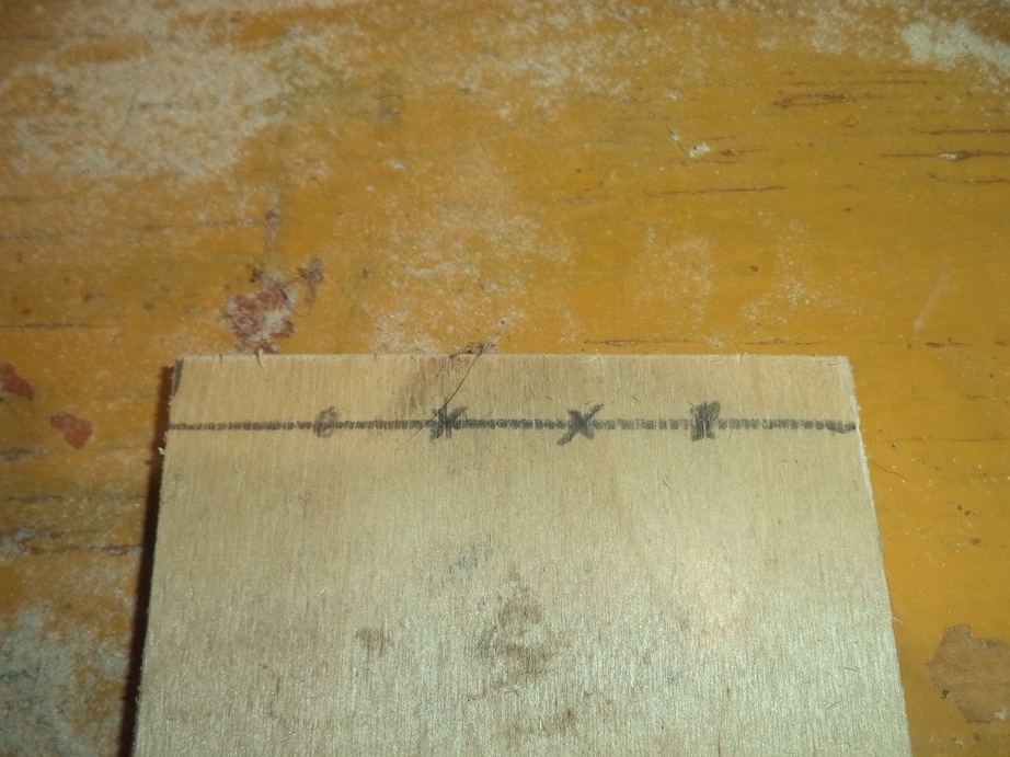
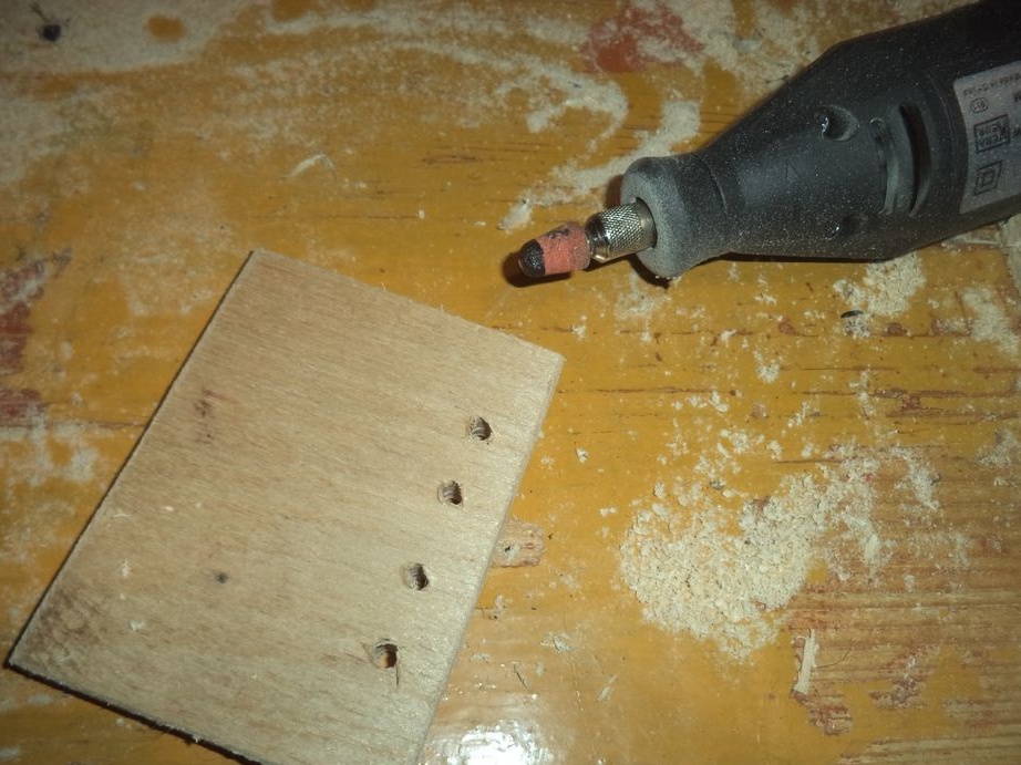
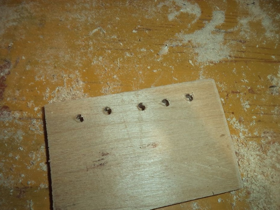
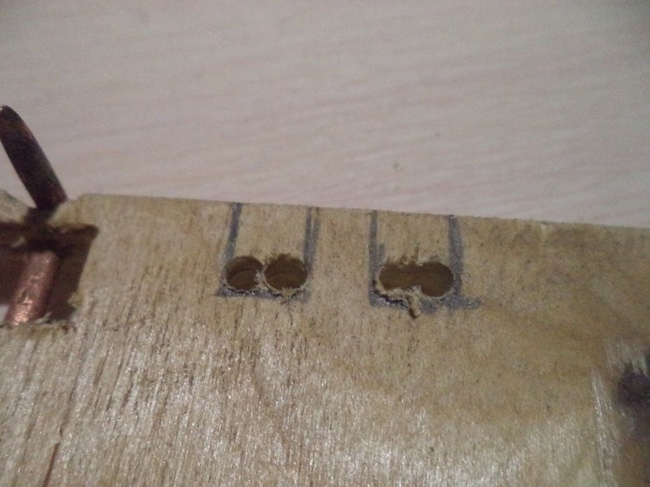
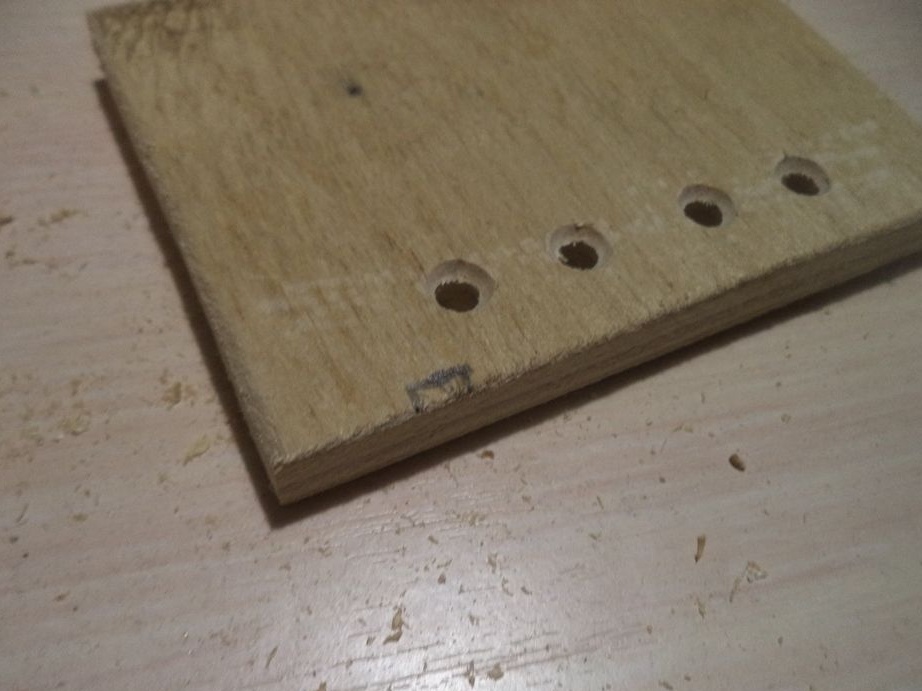
On one of the parts on which the recess was made, we drill holes with a mesh.
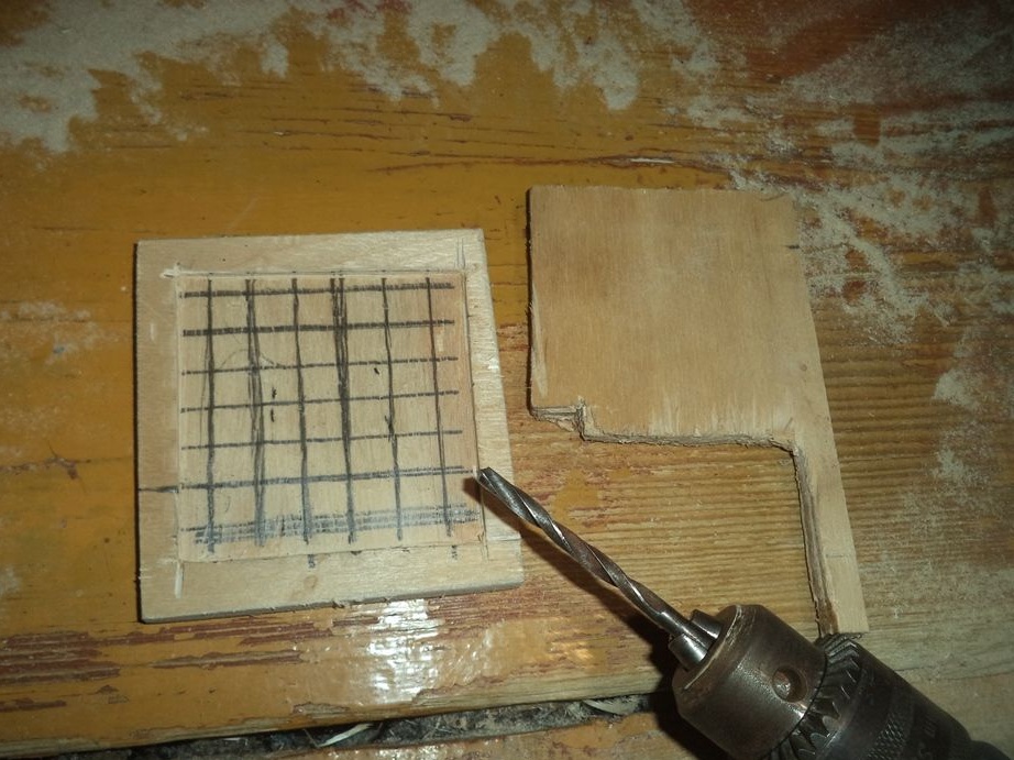
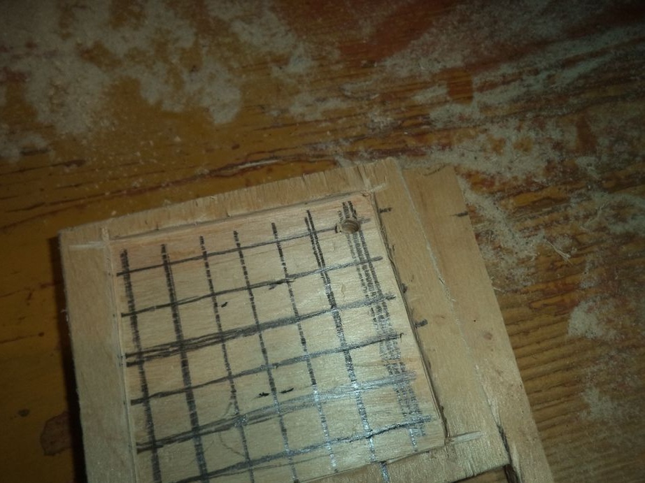
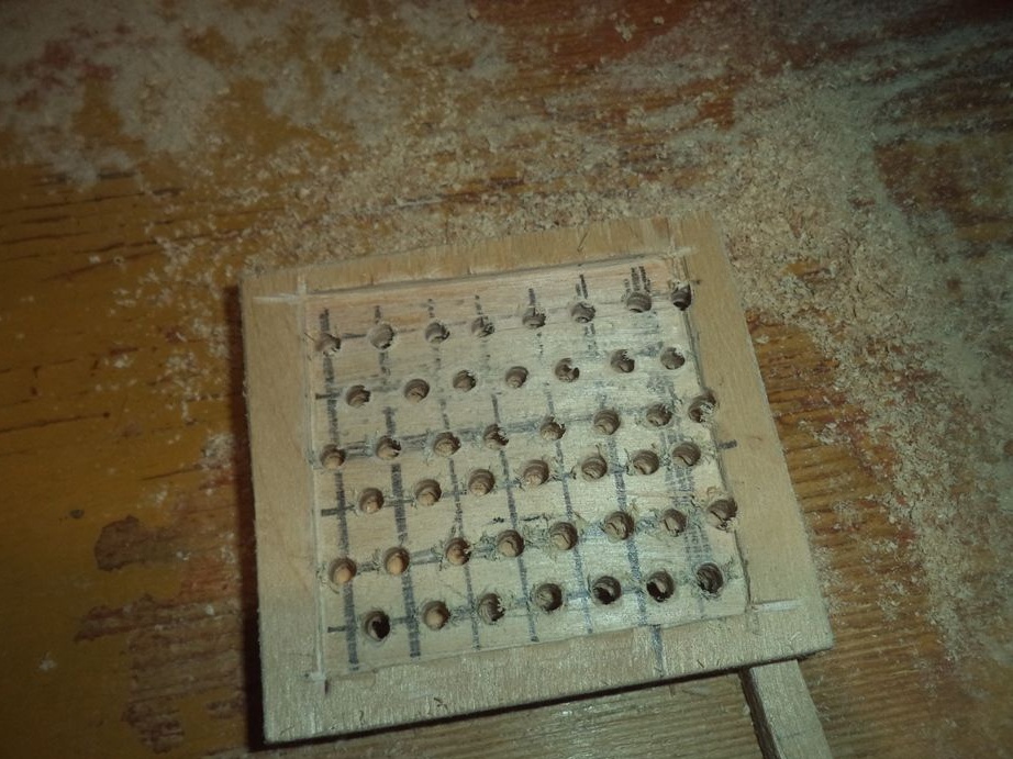
We process them with a drill.
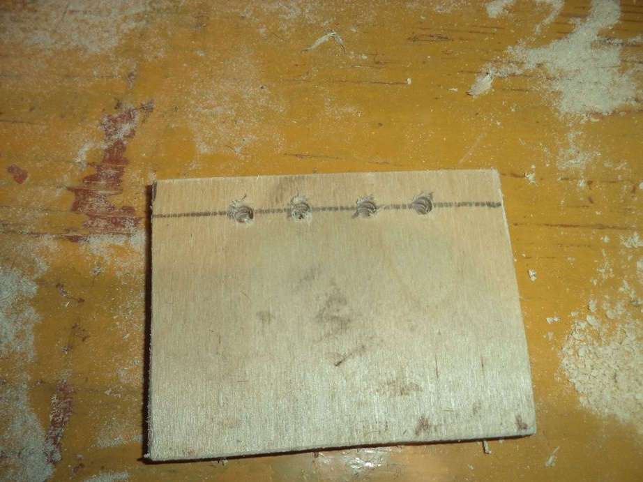
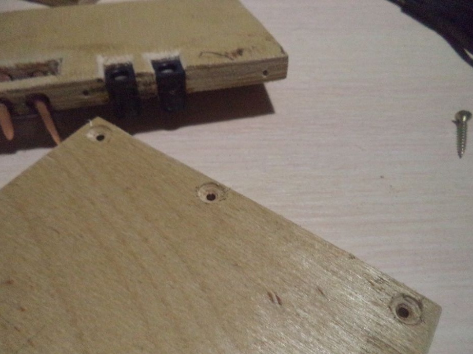
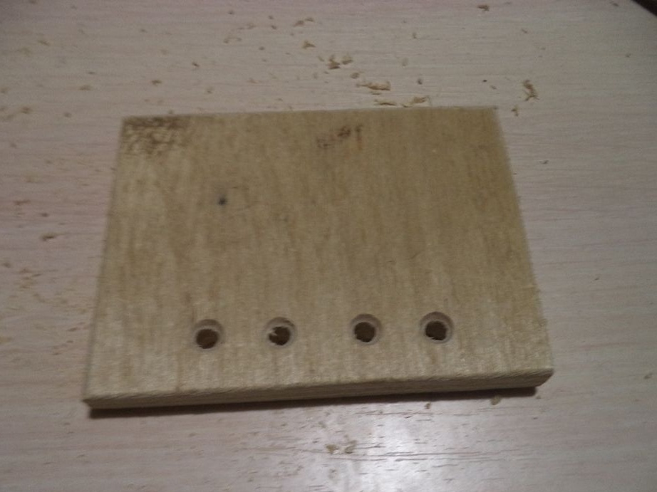
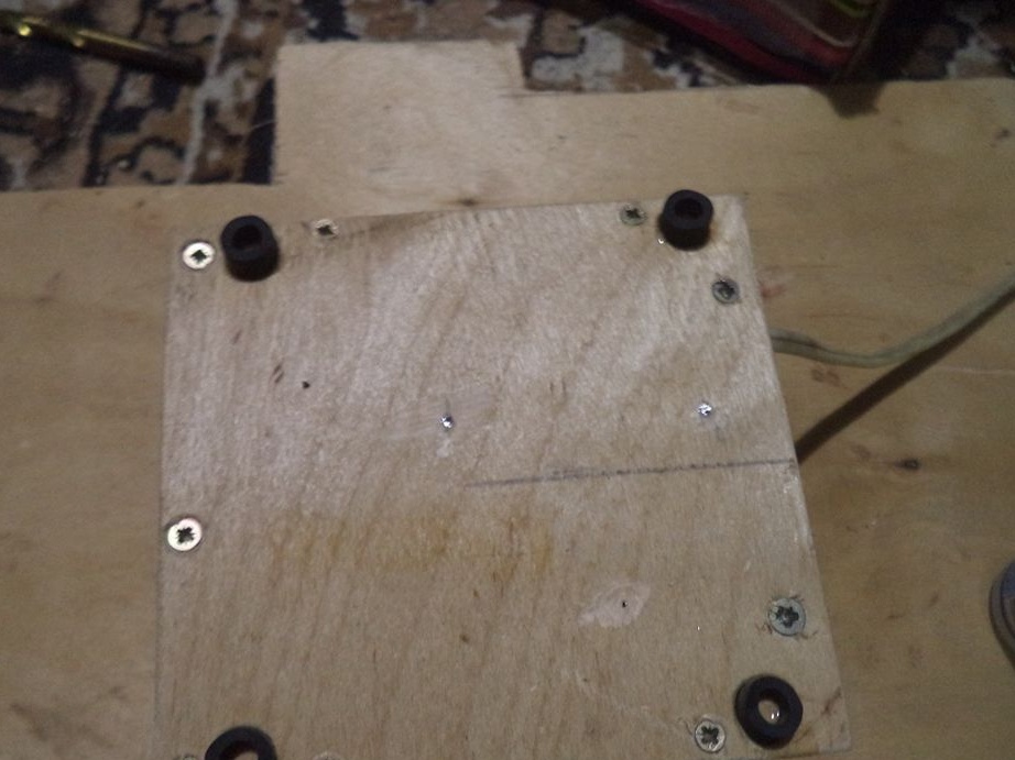
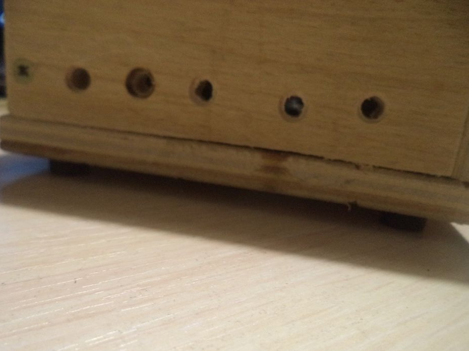
On three other parts, in addition to the front, we also drill holes in the lower place of the parts.
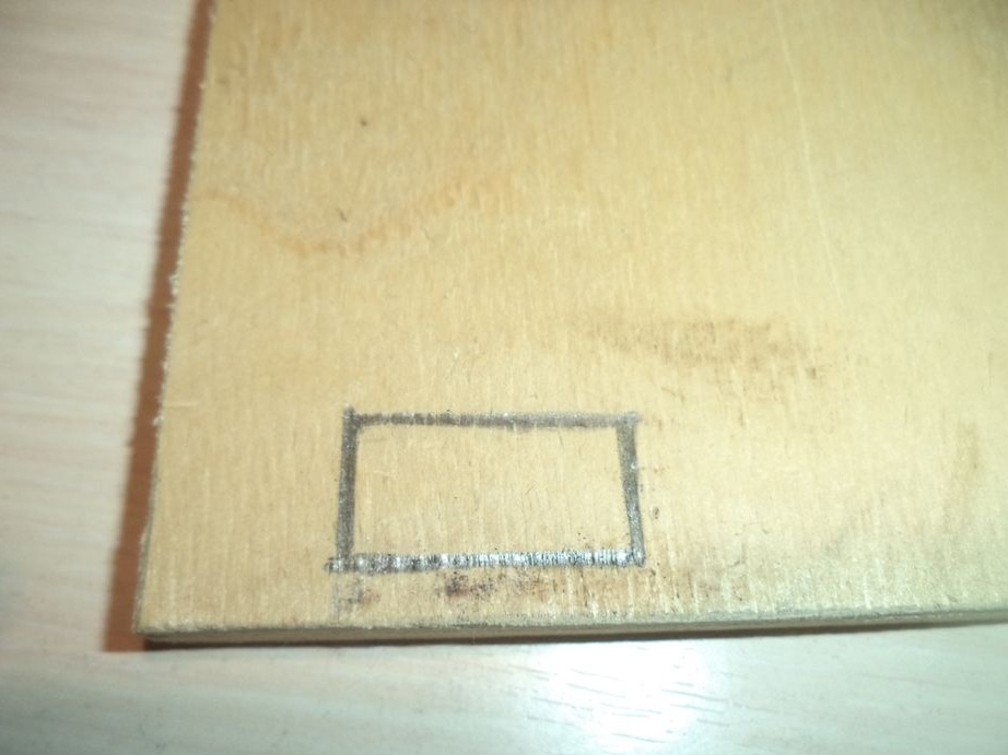
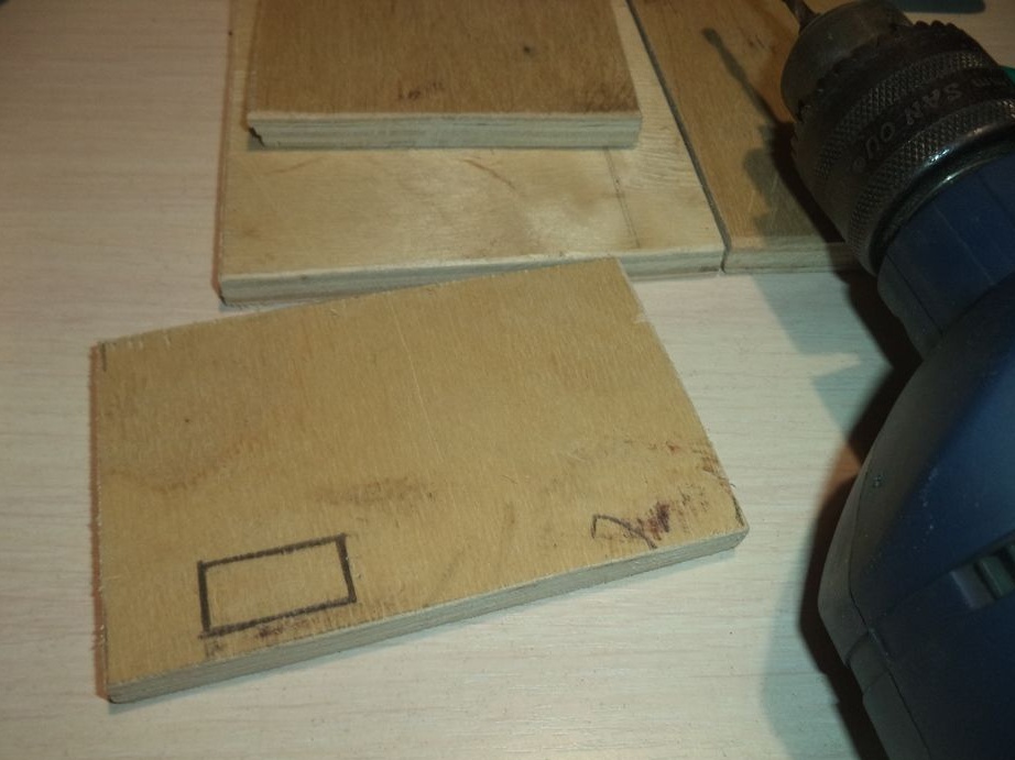
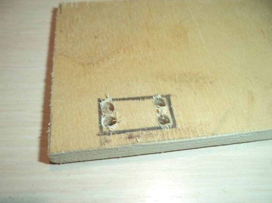
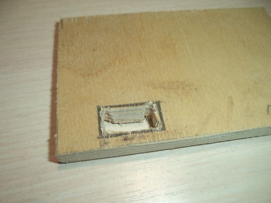
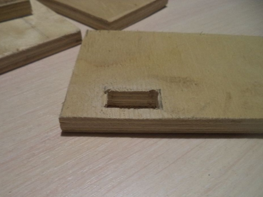
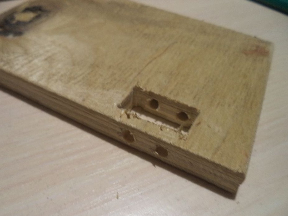
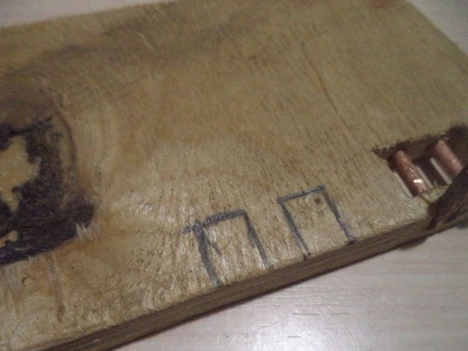
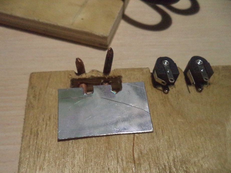
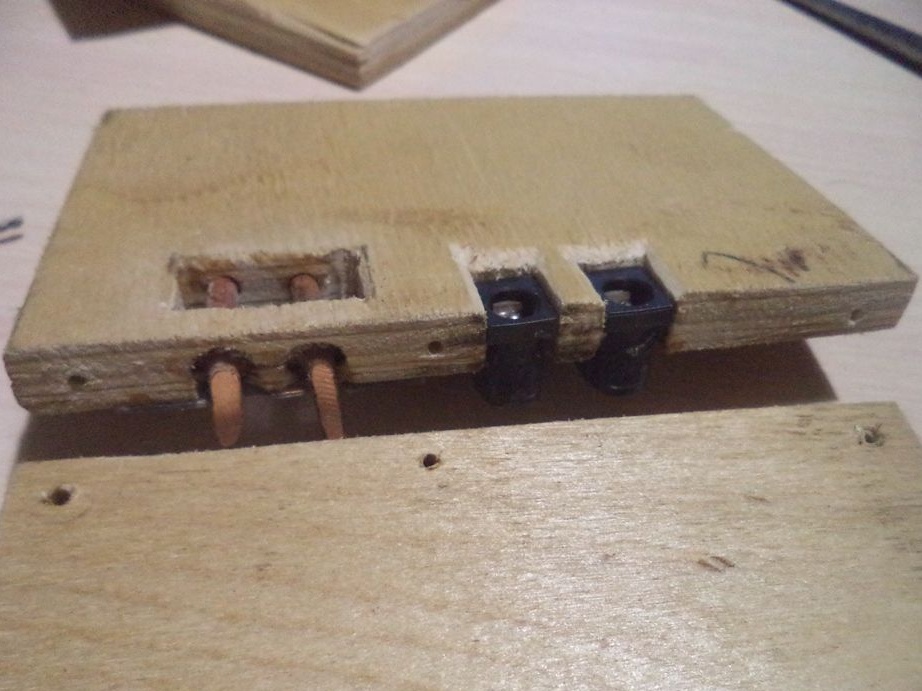
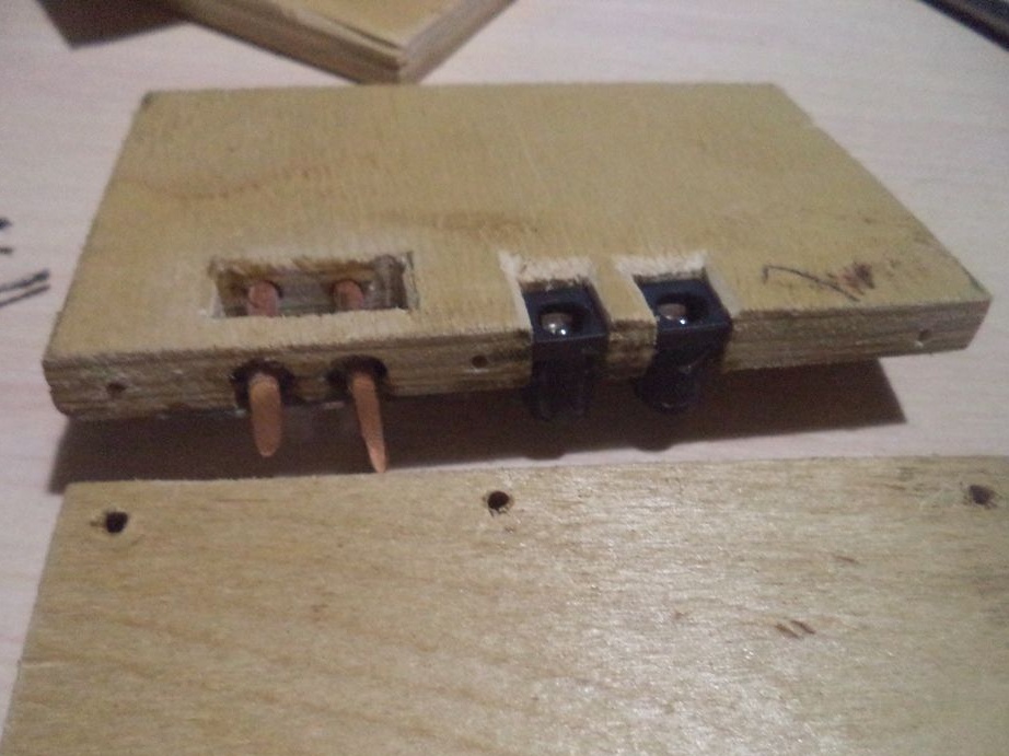
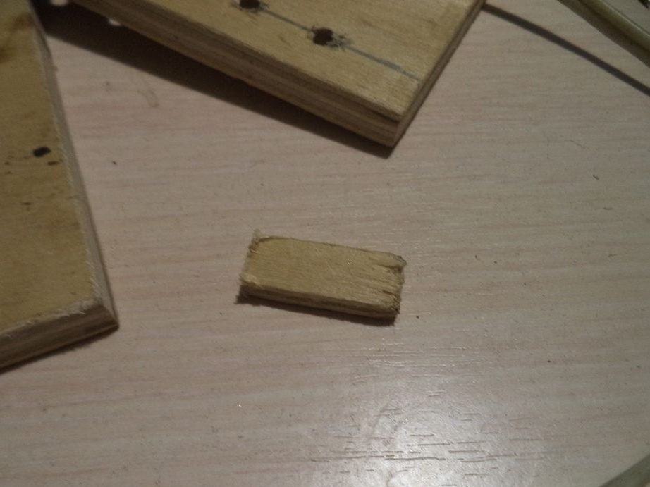
On the remaining part, which is larger than the previous side parts, we make a rectangular hole and rectangular recesses.
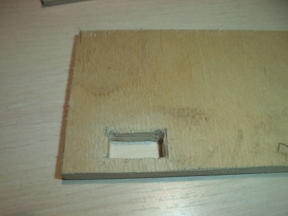
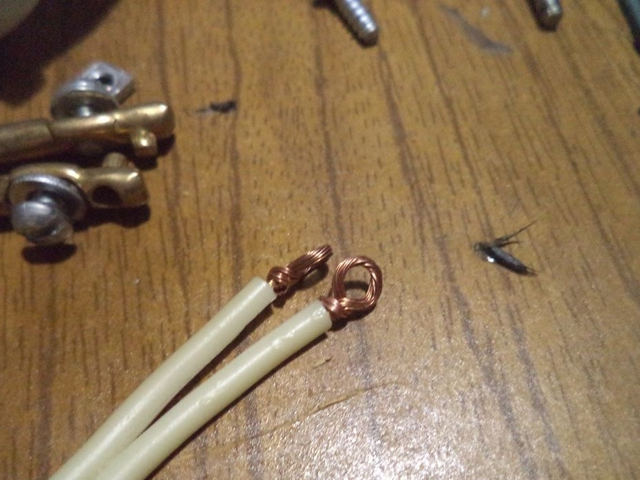
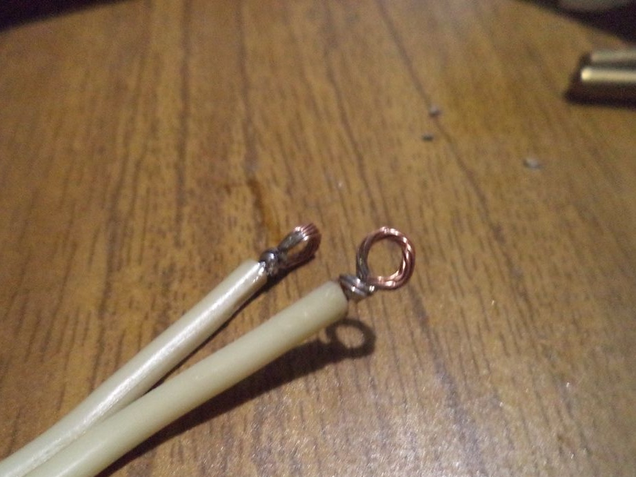
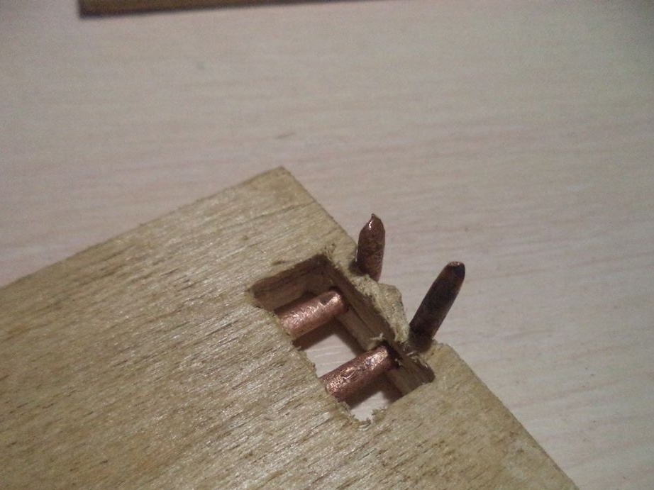
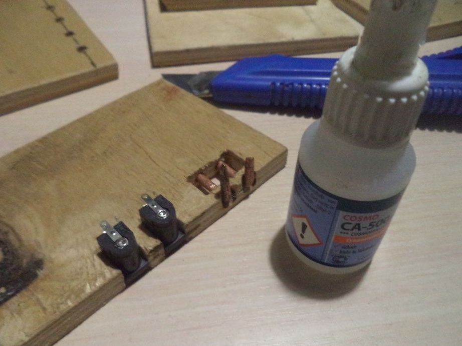
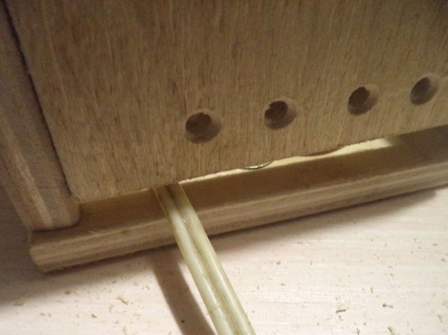
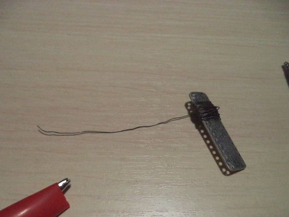
Now we attach this copper wire to this hole.
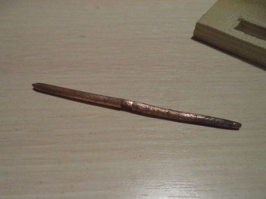
To do this, through this rectangular hole we drill two identical holes with a diameter into this copper wire.
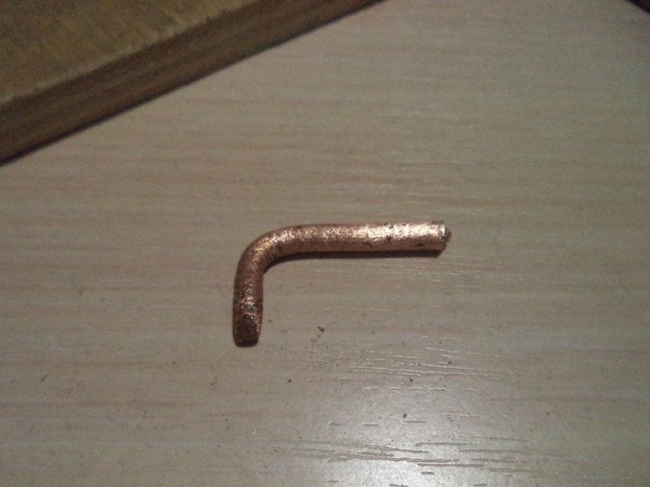
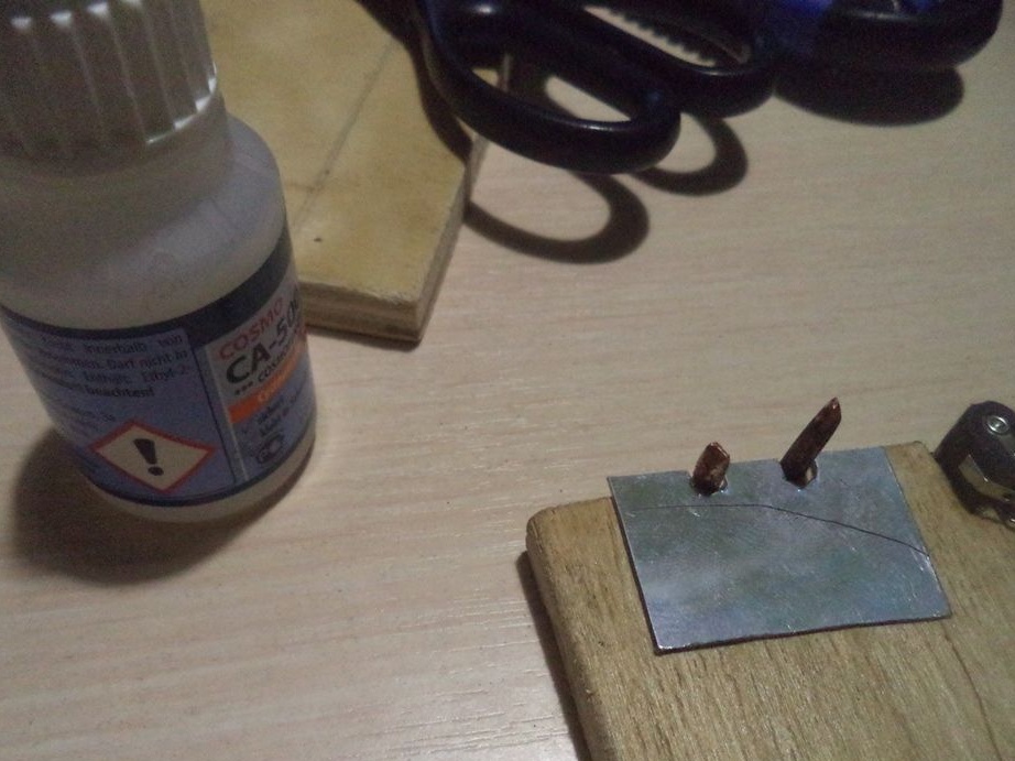
We cut the wire in half and bend the l-shaped form from the two wires obtained.
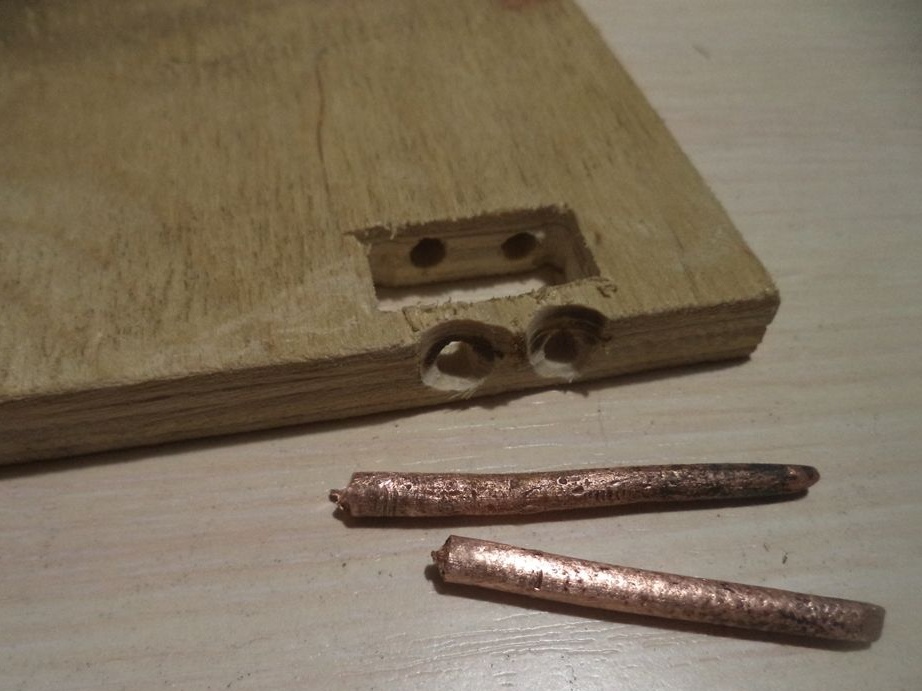
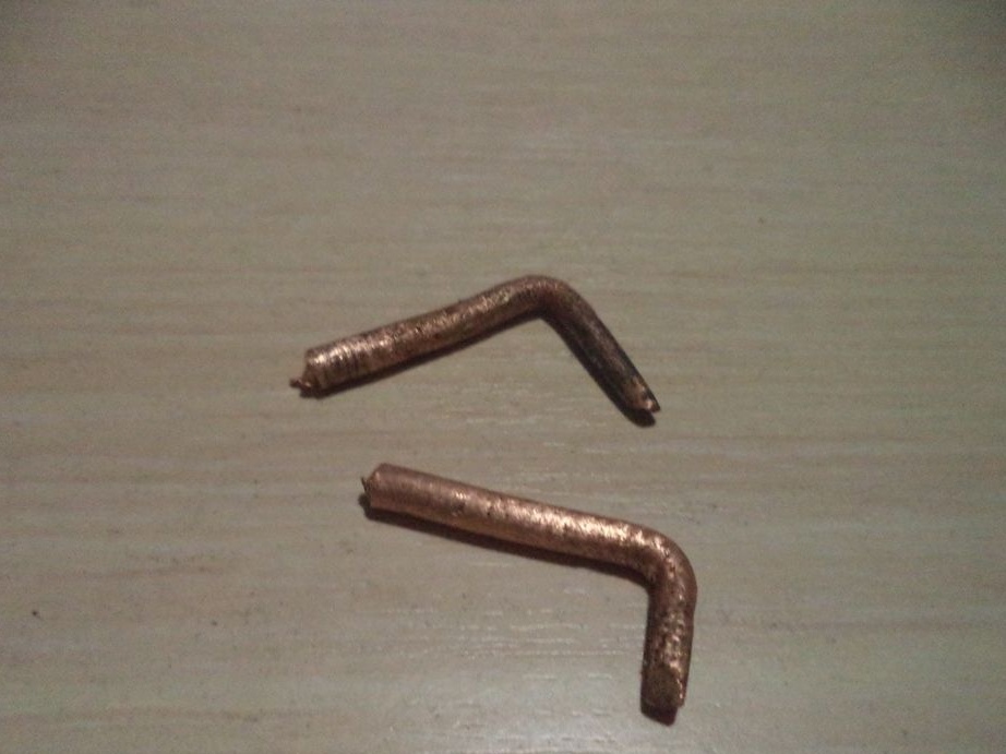
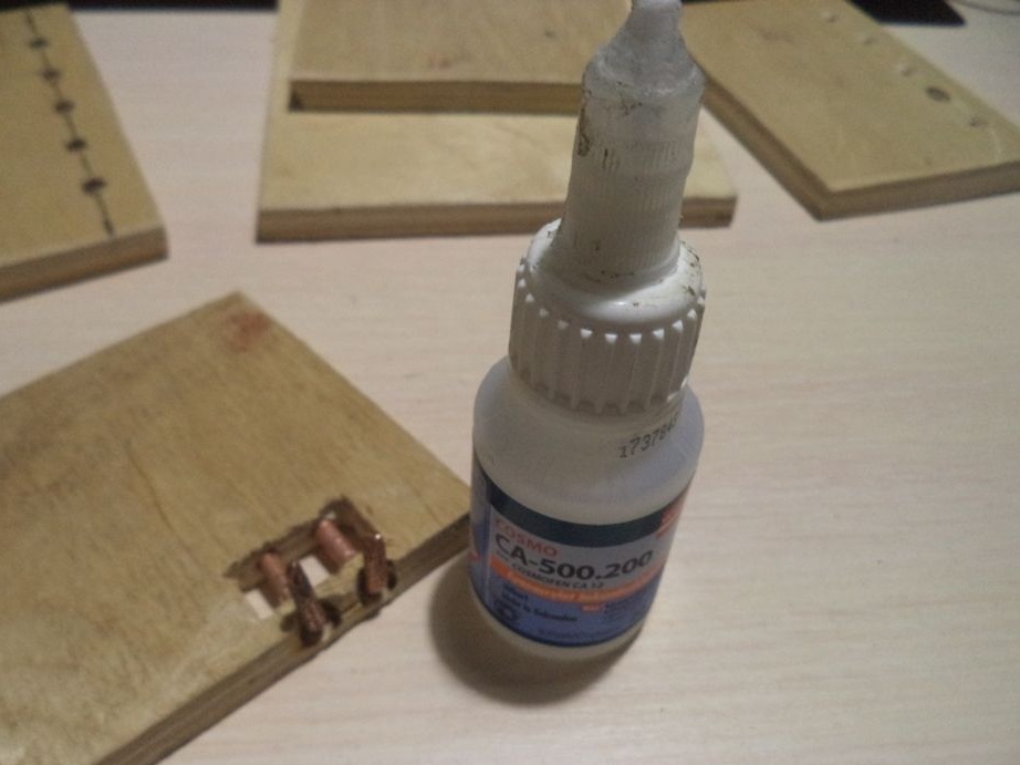
We insert the obtained two parts into the holes and glue them there with super glue.
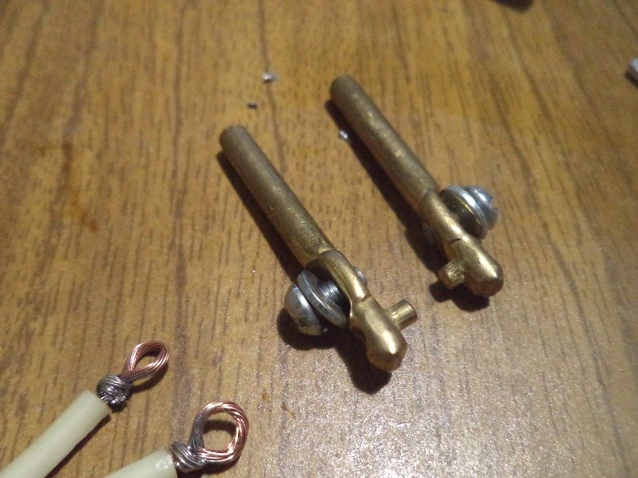
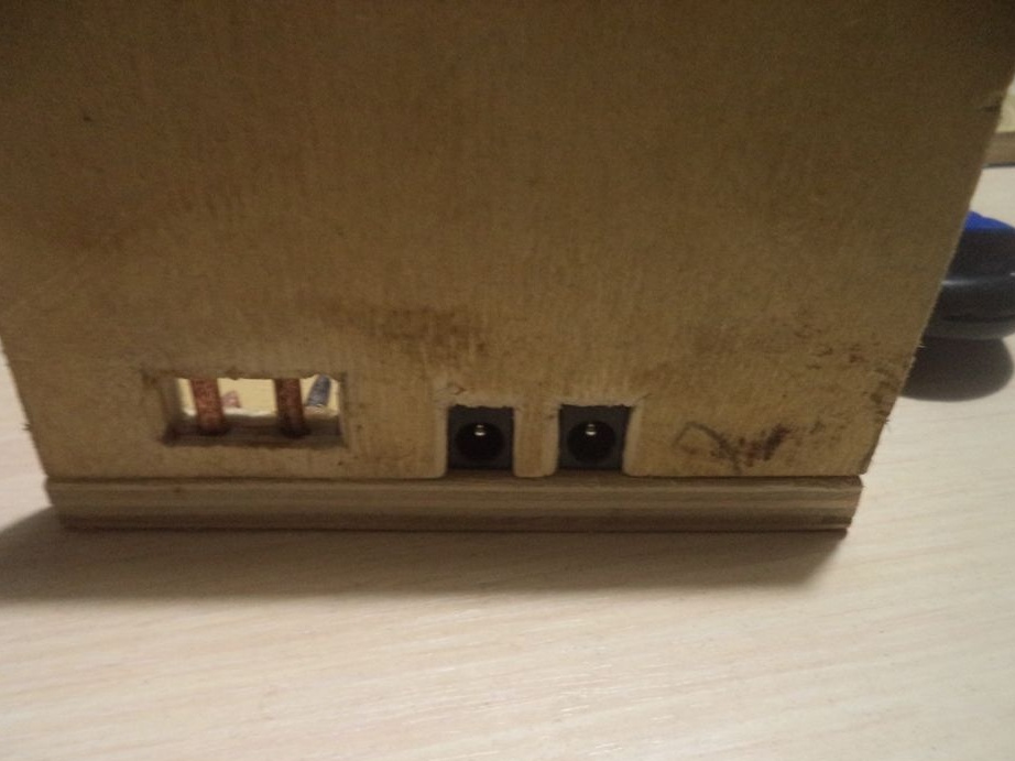
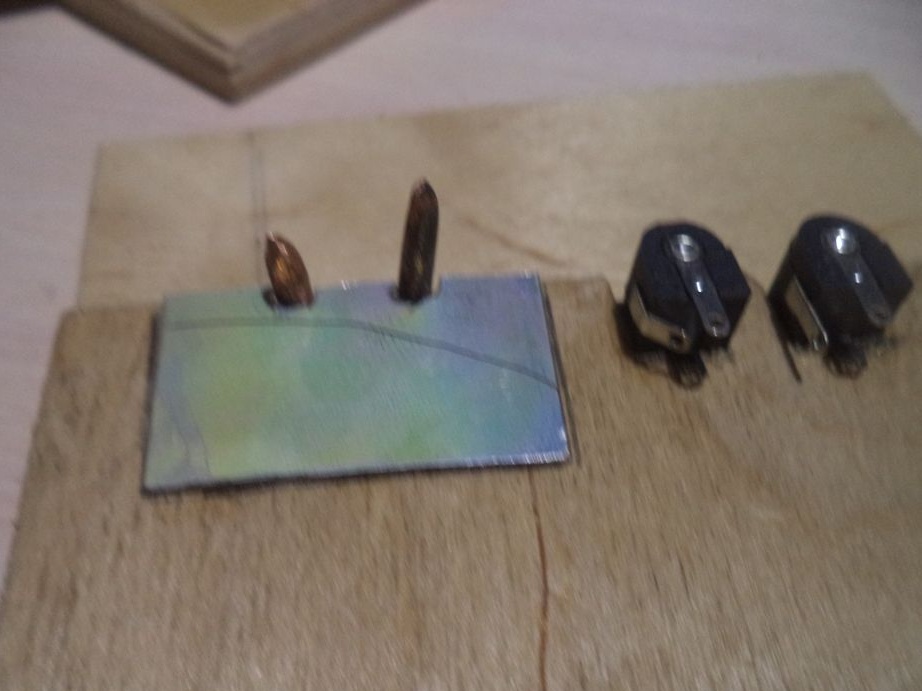
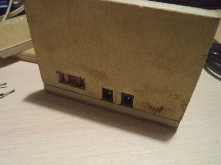
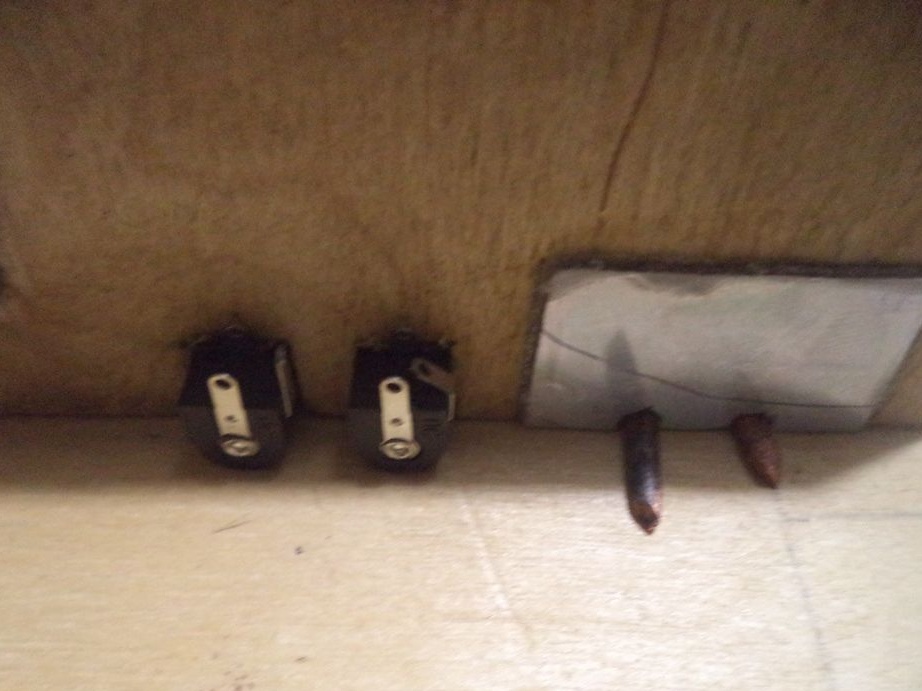
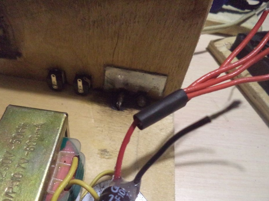
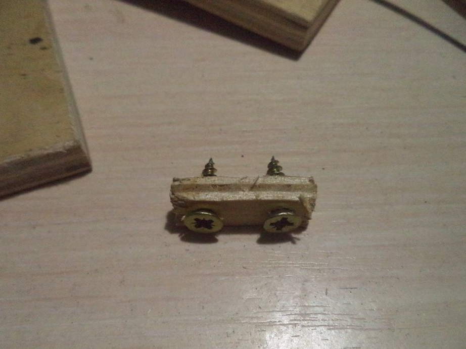
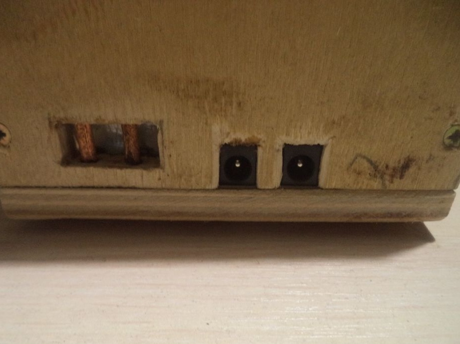
Now we take the connectors designed for 12 volts and prepare seats for them.
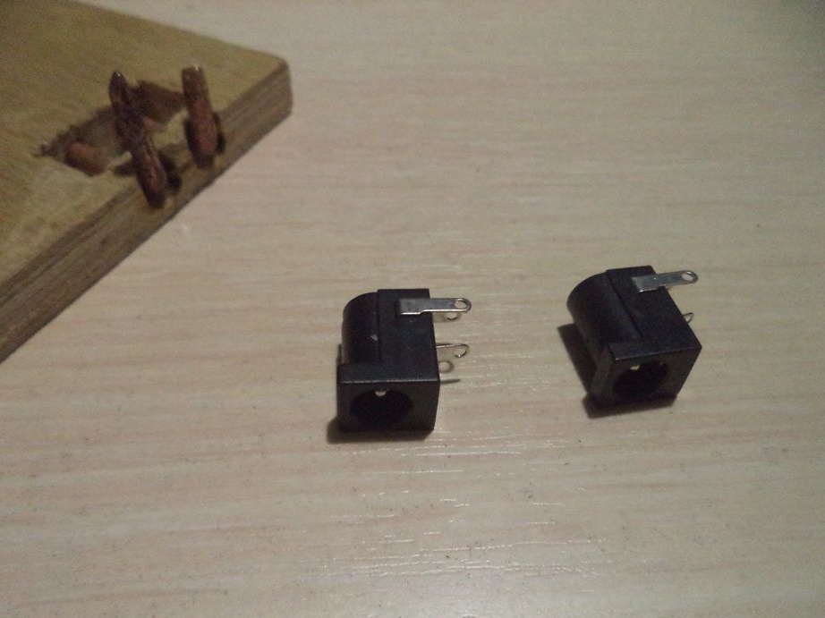
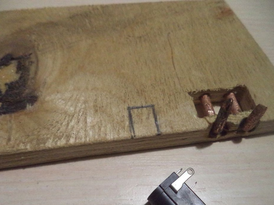
We insert the connectors into place and glue them with super glue.
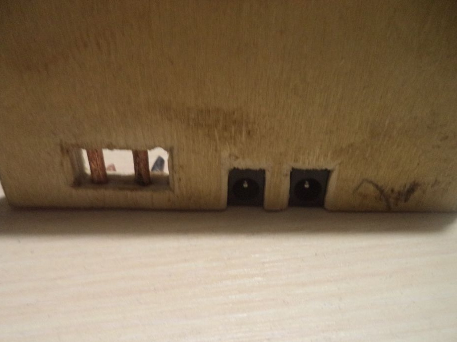
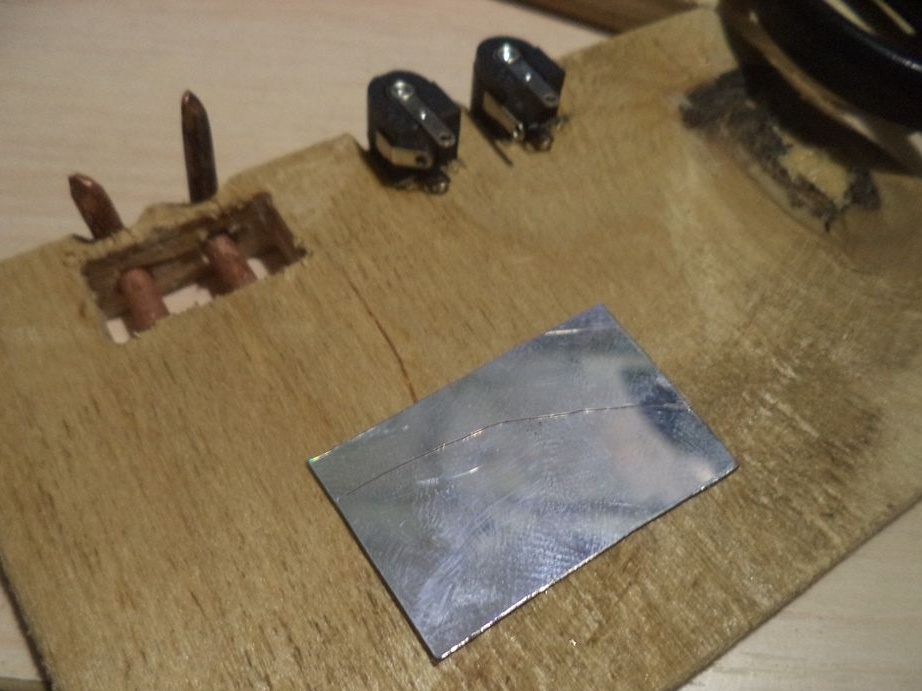
Using a rectangle from the disk, close the rectangular window.
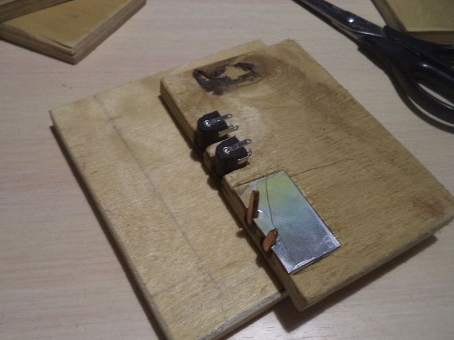
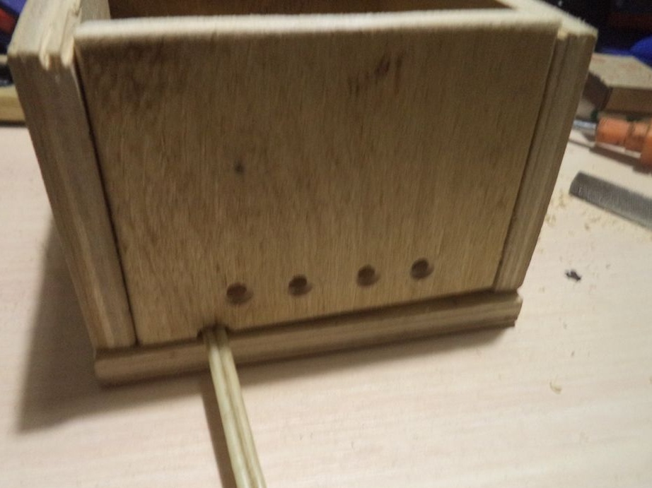
We begin to assemble the body. I hope everything will be clear from the photographs, how I fixed everything.
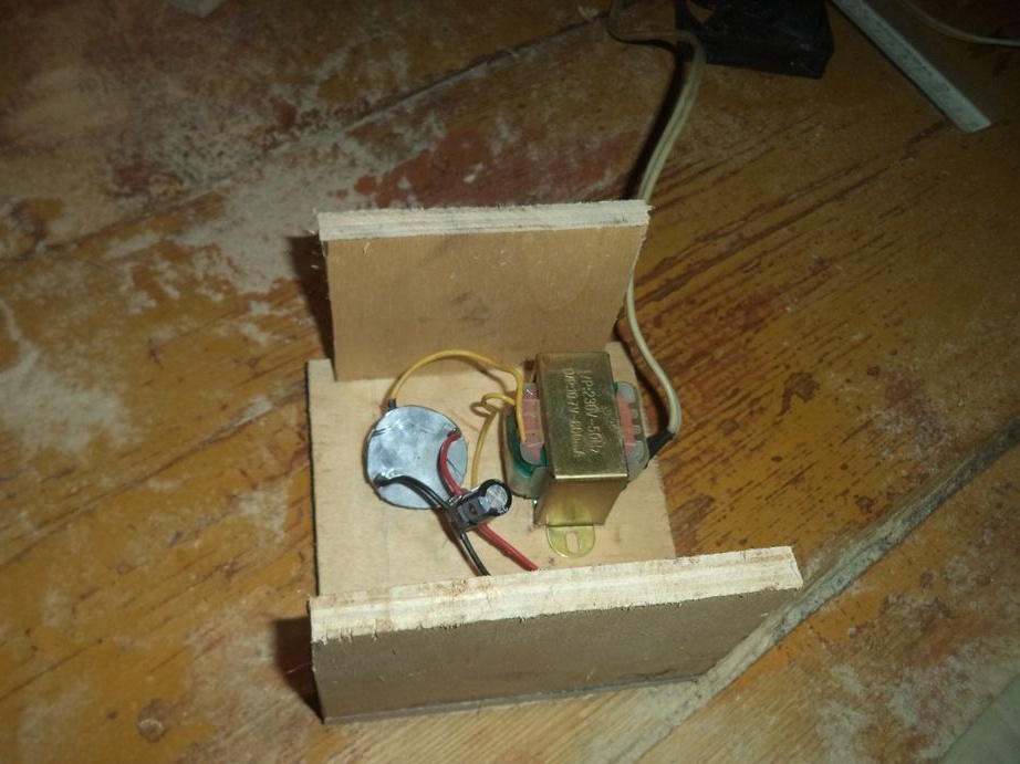
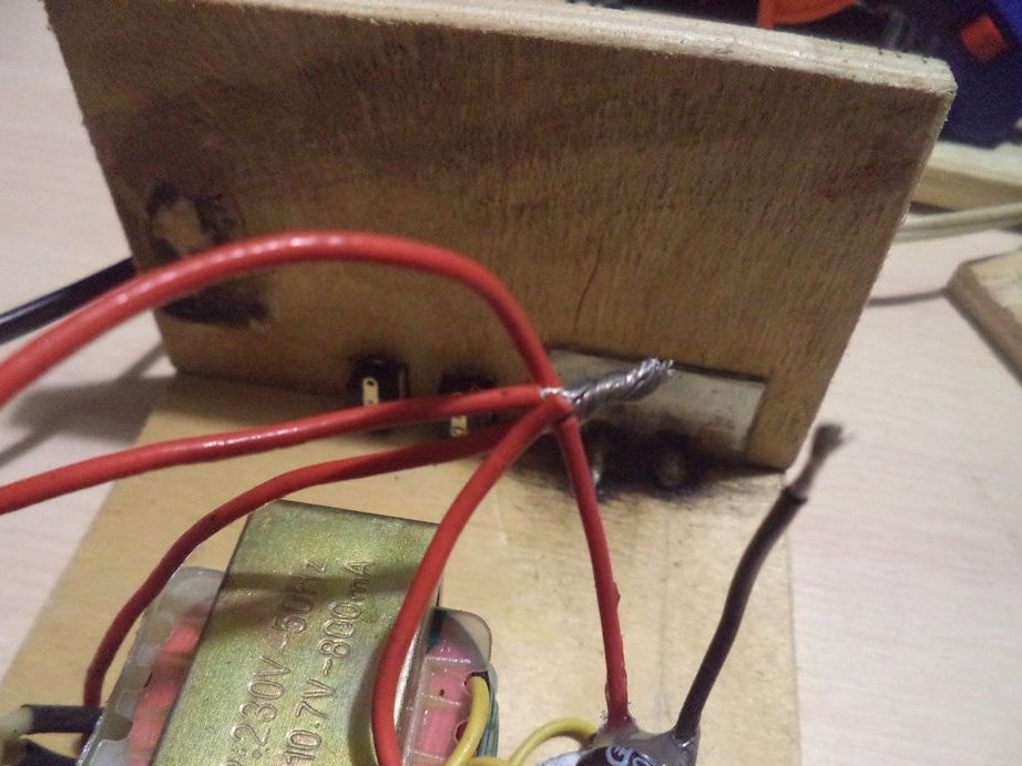
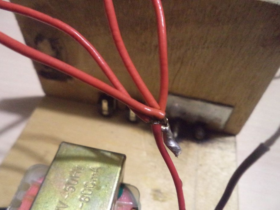
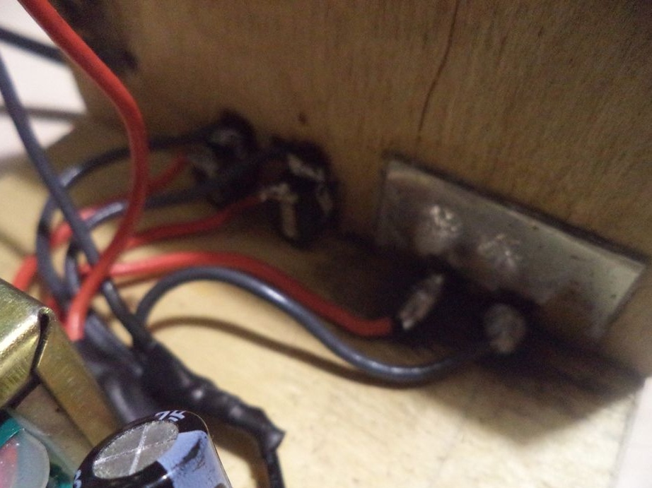
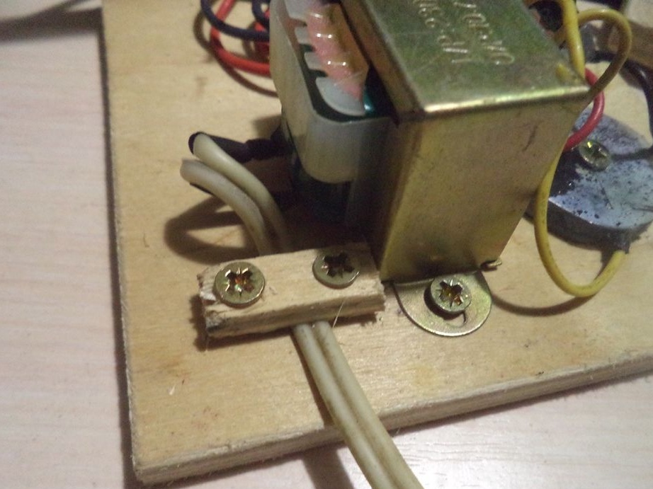
We fix the transformer and the diode bridge to the housing.
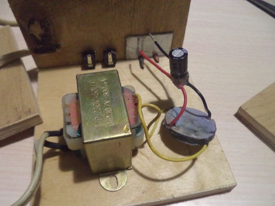
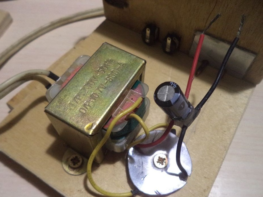
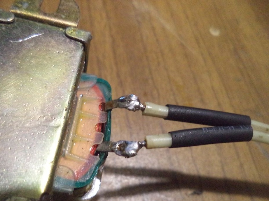
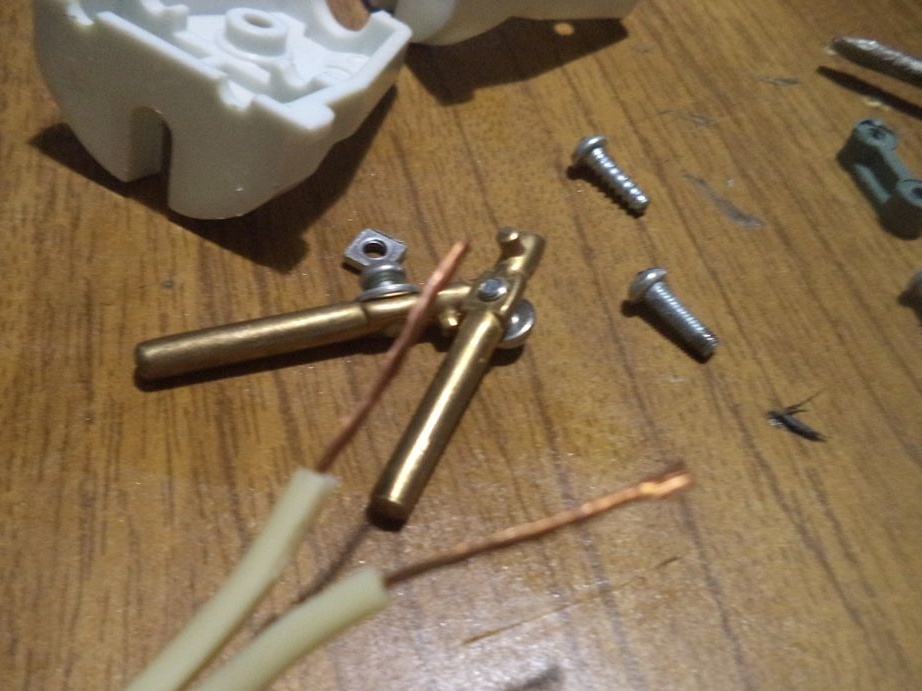
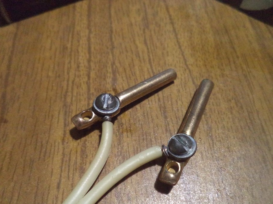
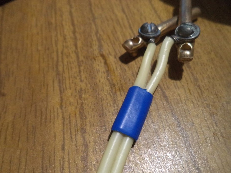
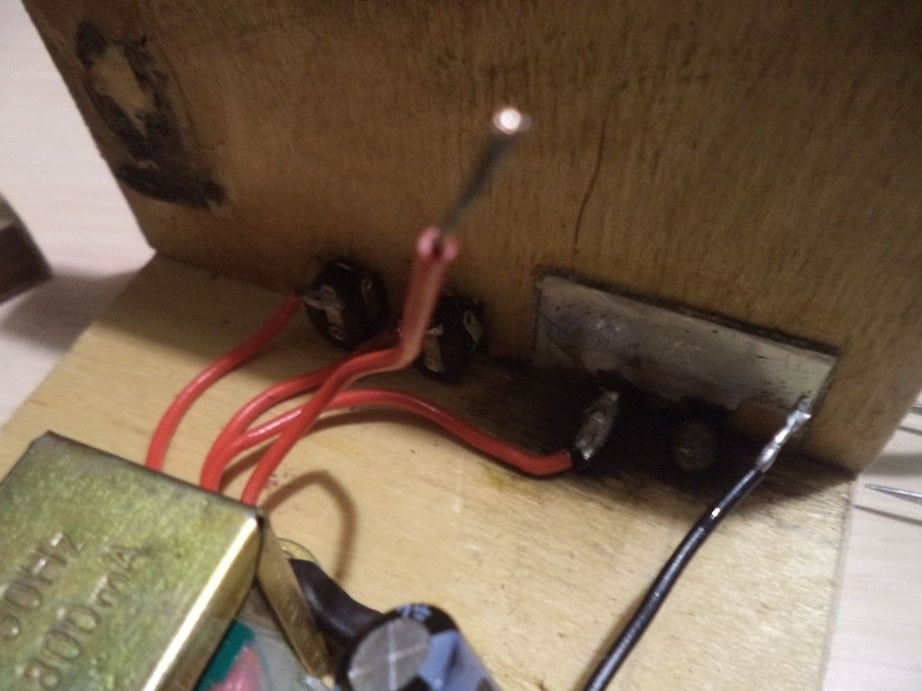
Now we solder the wires to the connectors and the terminal on which the crocodile-type mounts will be attached.
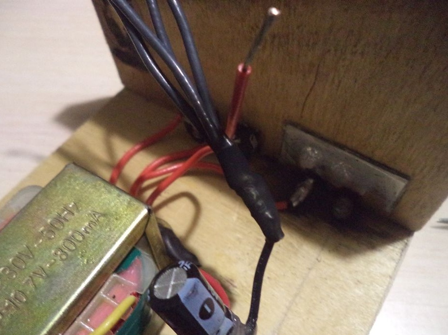
By the way, the remaining two wires will be connected to a fan, which unfortunately I did not find right now (although I have one, you can see it in the photographs, but if you connect it to the unit, the unit will begin to vibrate and make an unpleasant sound, since two blades of the fan are broken, so it’s better to get a new one and connect a new one).
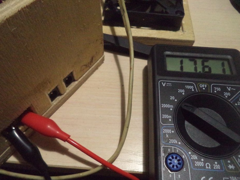
Again, check the readings with a multimeter. The voltage has already increased to 17.61 volts.
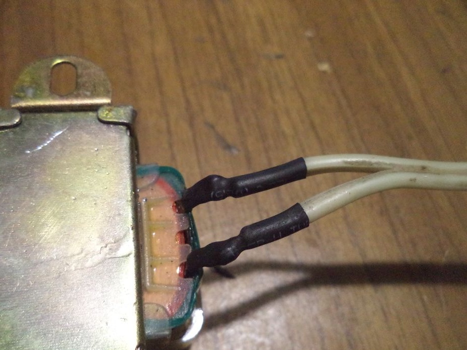
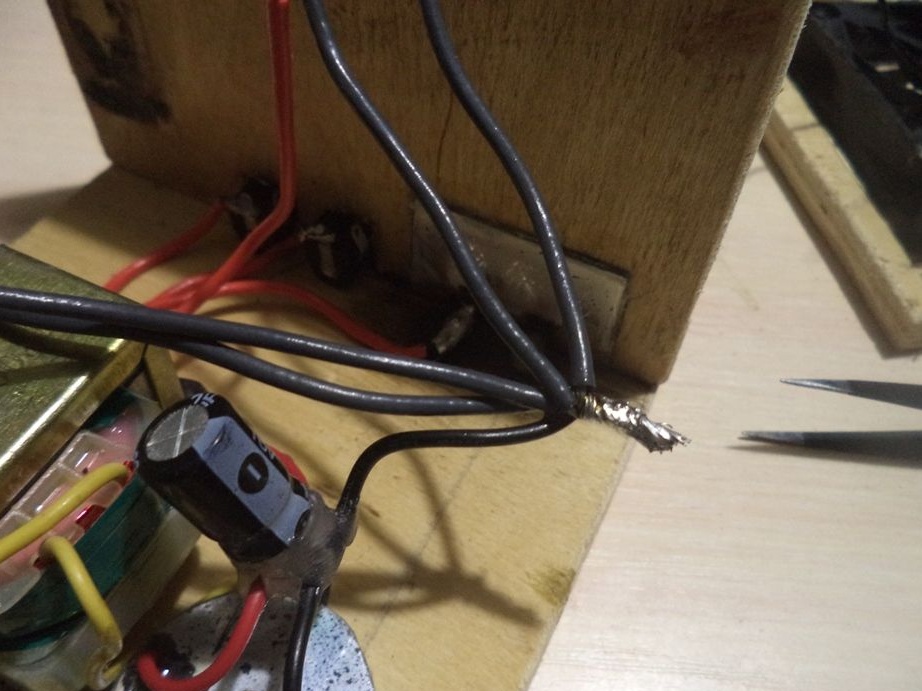
Now we fix the wire that will be connected to 220 volts as follows.
We continue to assemble the body.
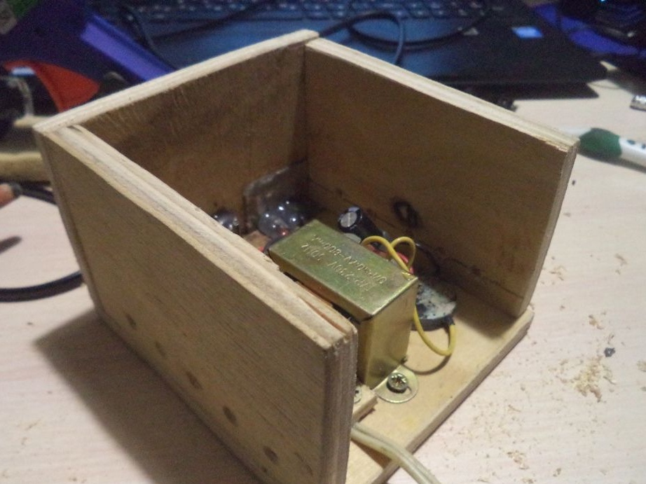
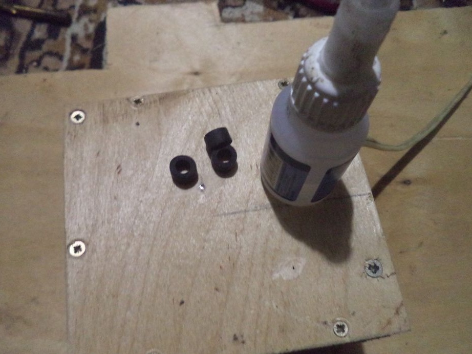
That's all, the power supply is almost ready, it remains to stick the legs from the rubber tube. We will stick the legs with super glue.
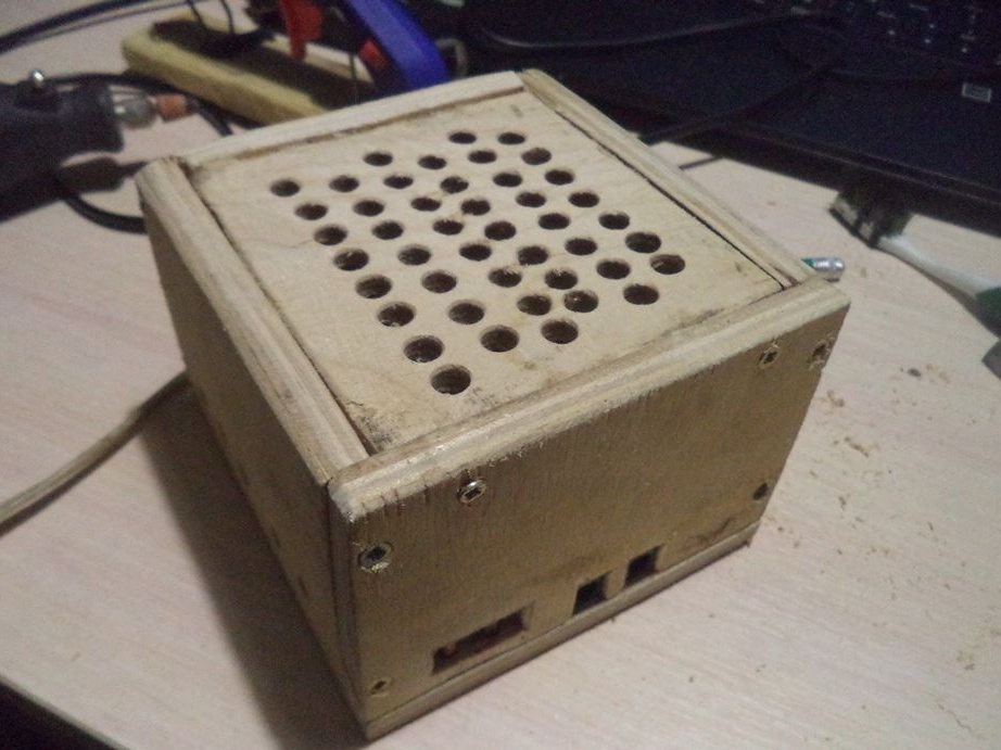
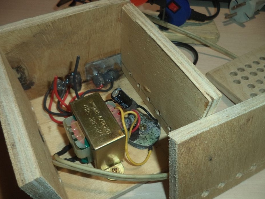
And now the power supply is completely ready, excluding the cooling system, which will still be installed.
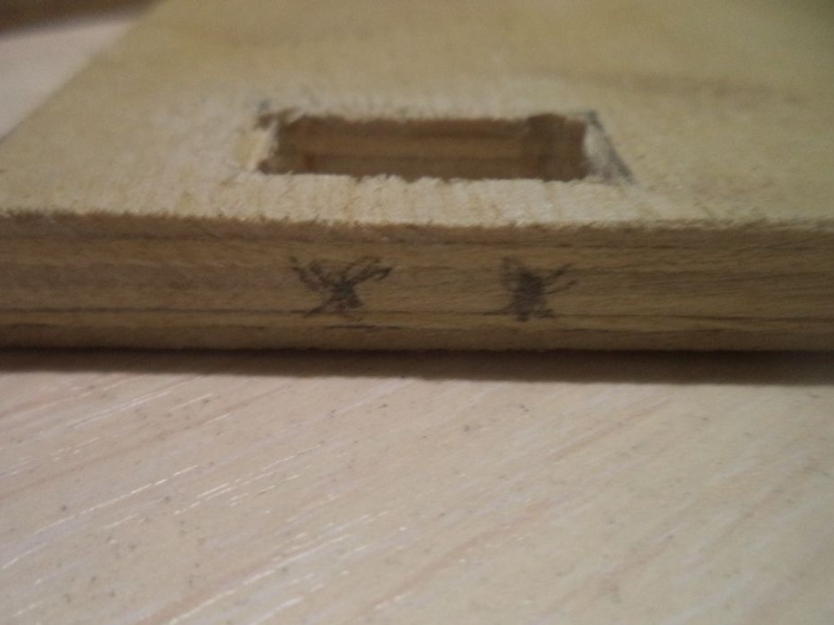
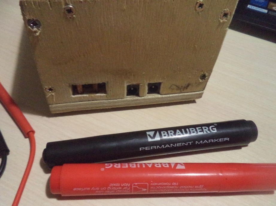
Now mark the conclusion. Red - plus, black - minus, permanent markers will help us with this.
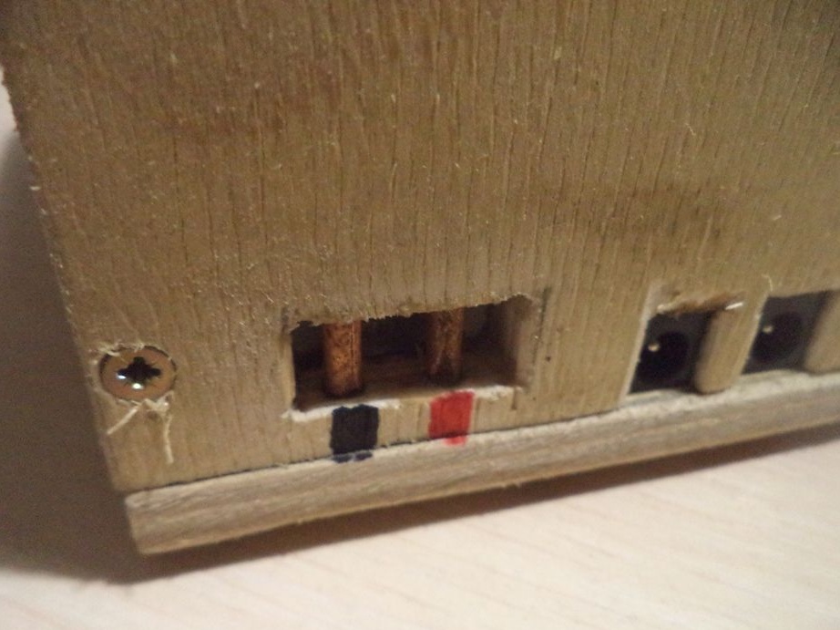
This is how the connection will be made.
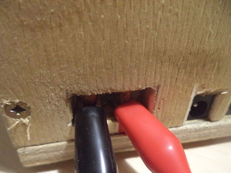
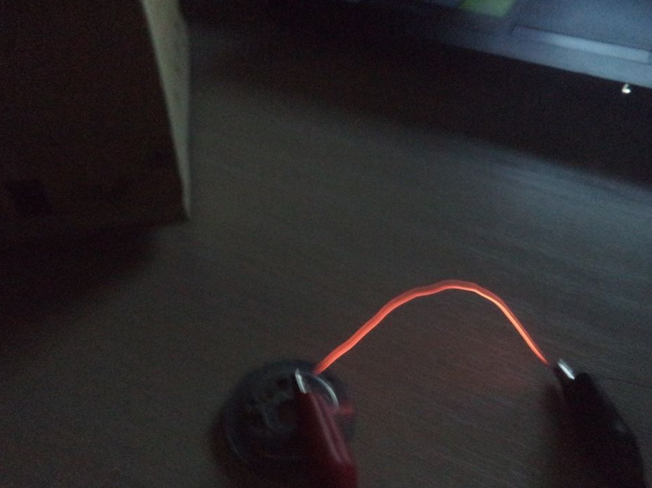
We test our power supply with a nichrome wire.
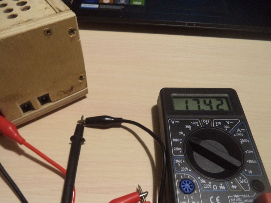
But what kind of voltage the power supply produces at the end.
To make a simple power supply is not at all difficult, since it is simple, but more complex, it will also be interesting to assemble, except for the case. And for this power supply, I can make special devices, which I will show in my next articles.
This article is over, thank you all for your time on my homemade product.