» Electronics » Power supplies »Power supply IPS-1 second life

IPS-1 power supply second life

IPS-1 modernization.


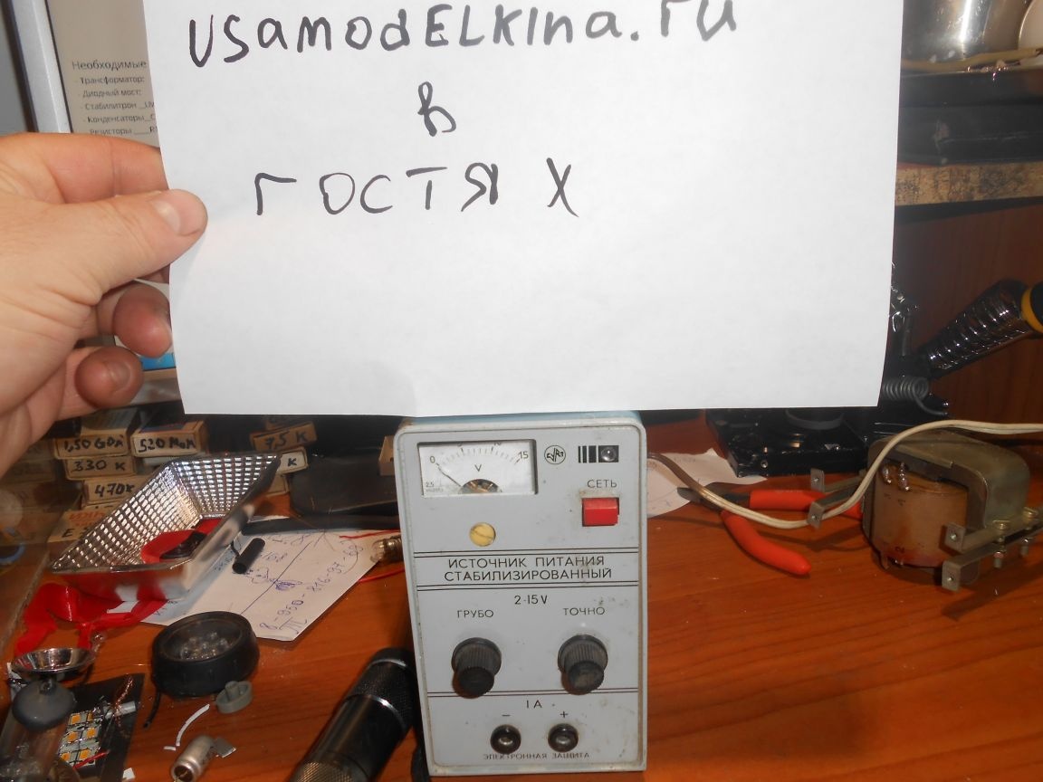
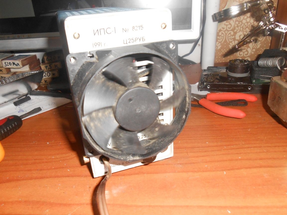
I fell into the hands of the rarity of Soviet times IPS-1


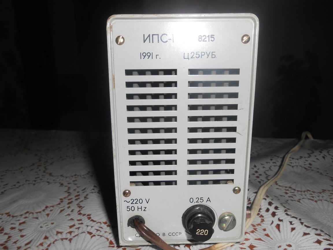
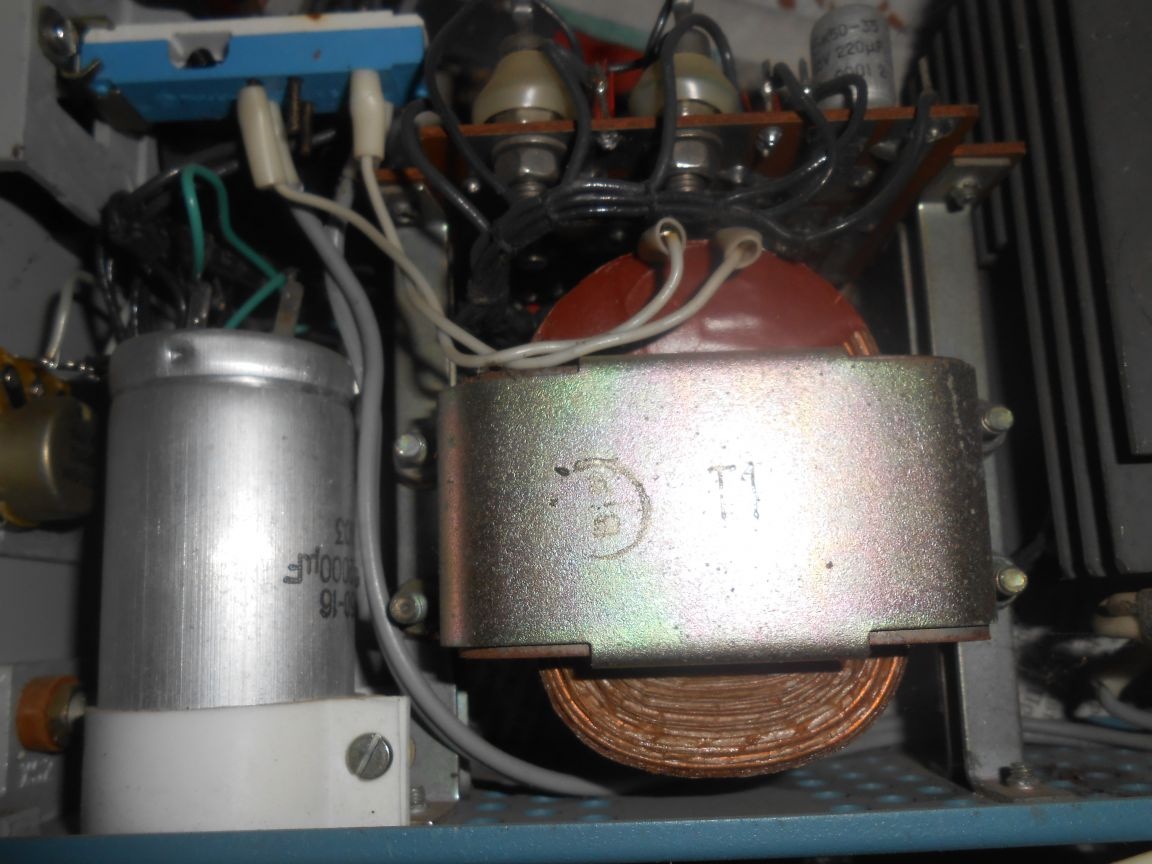
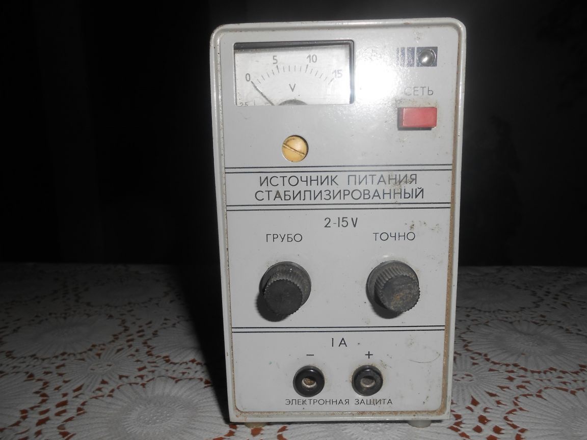
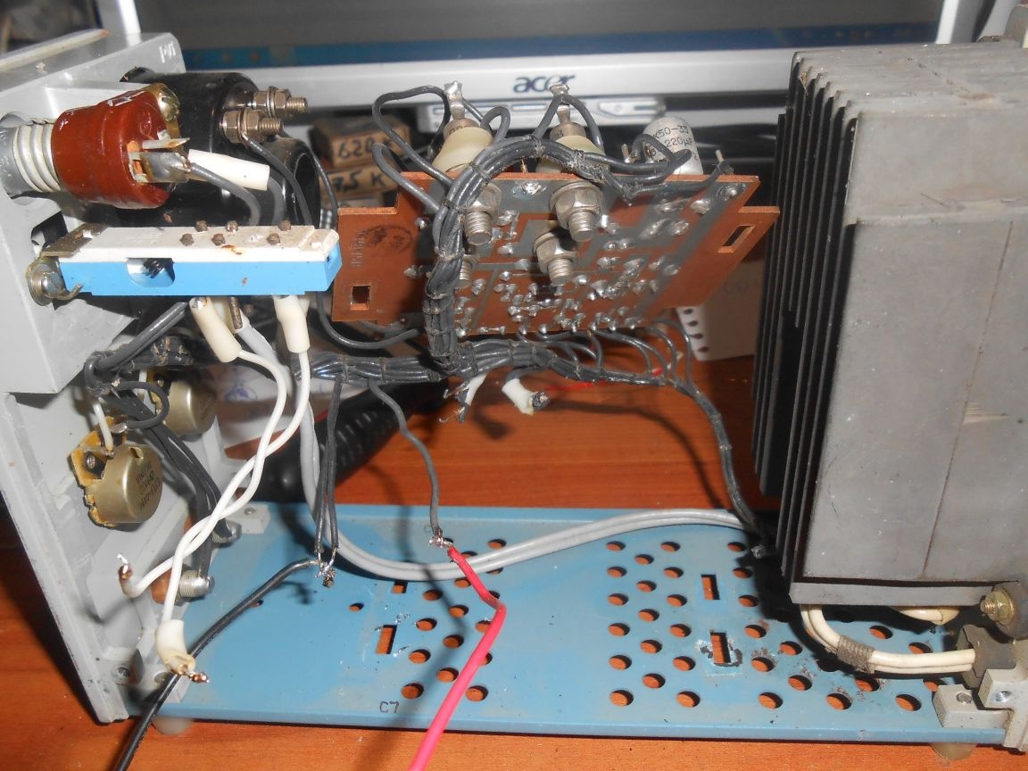
The power source IPS-1 is a successful product of the Soviet industry.
Adjustable 0-15V (2-15V this modification) source with a current limiting mode of 1A, easily “overclocked” to 1.5 A. Small size, high reliability.

Factory current protection operation up to 1A, output voltage 15V. The overall power of the installed transformer SHL16h32 is 38VA. Thus, the design of this unit has significant reserves, the implementation of which allowed to significantly increase the output power.
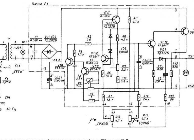
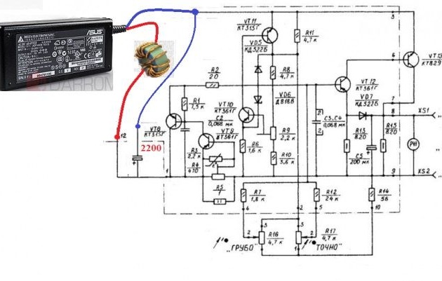
Scheme:

If we dismantle the transformer, rectifier, 2 healthy capacitors and plug in the charging from the laptop instead, we can easily get a power supply of twenty volts and five amperes. It all depends on the charging characteristics.
I had a 19 V 4.76 A charger on hand.

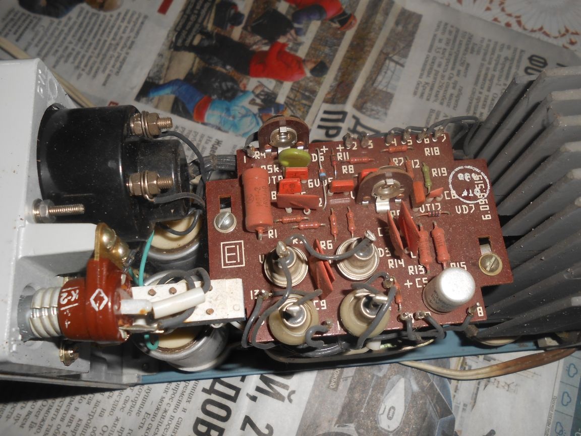
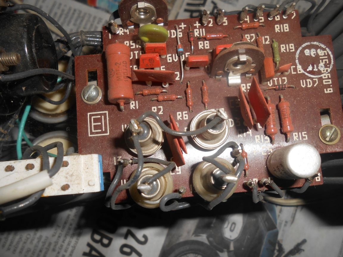
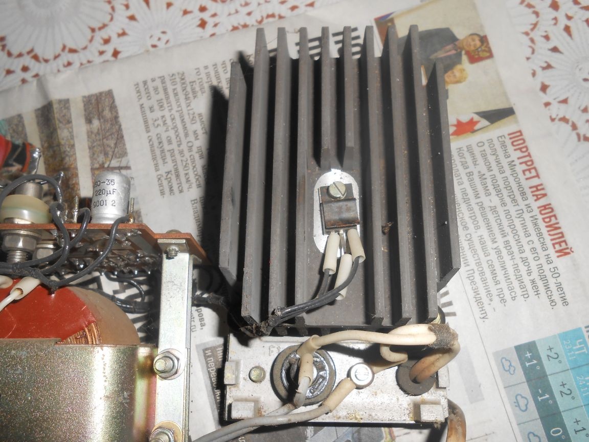
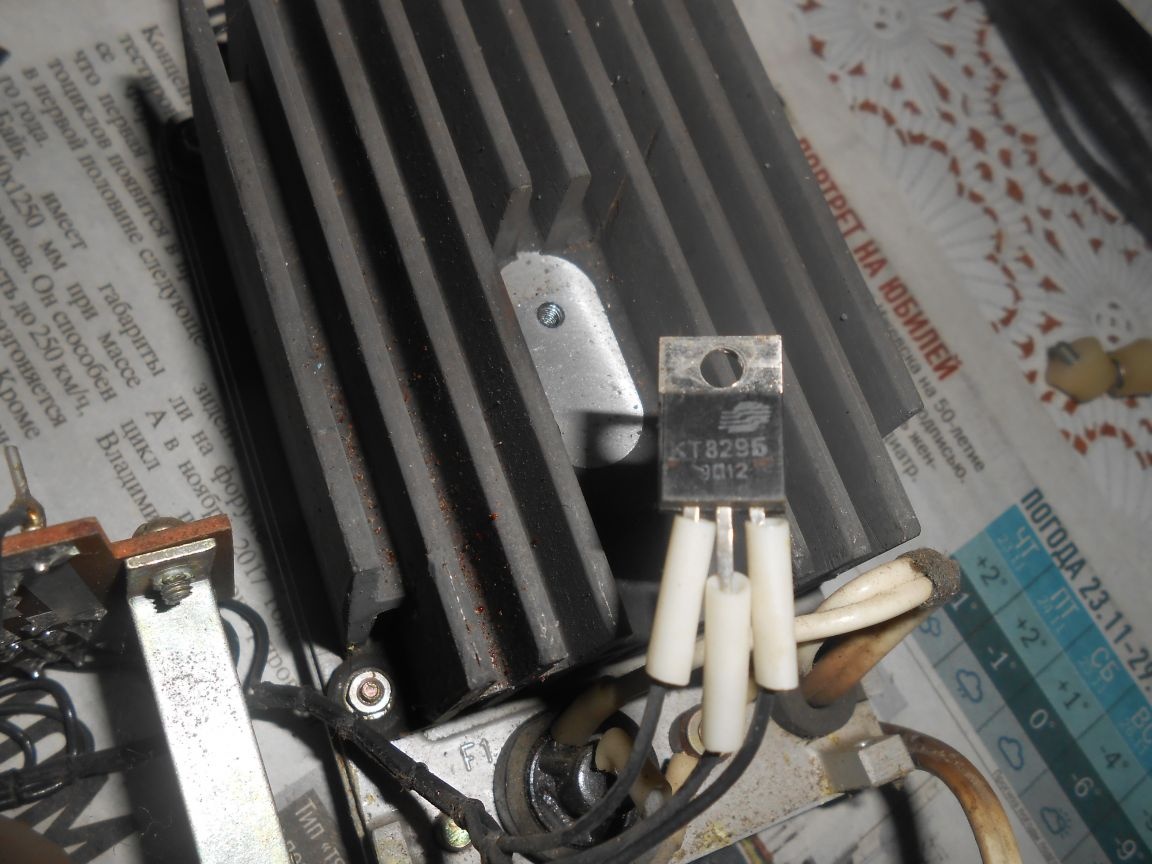
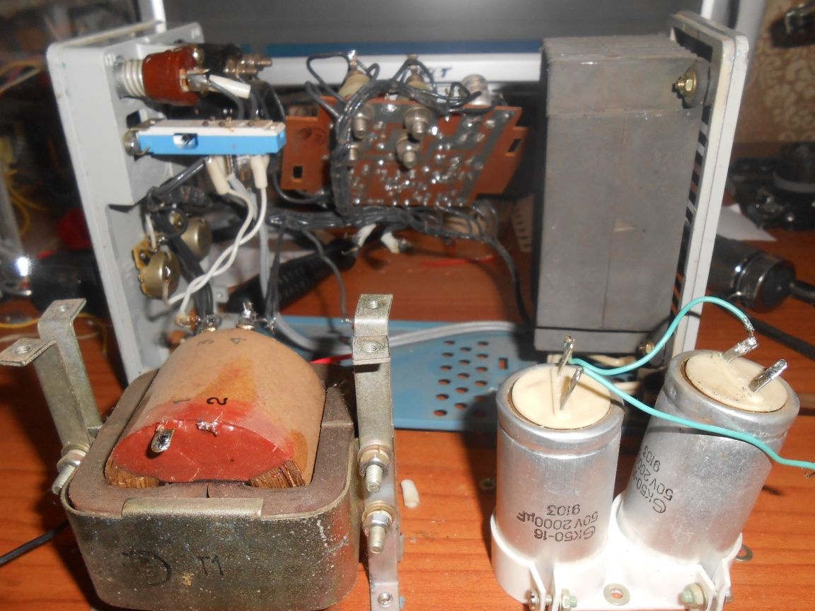
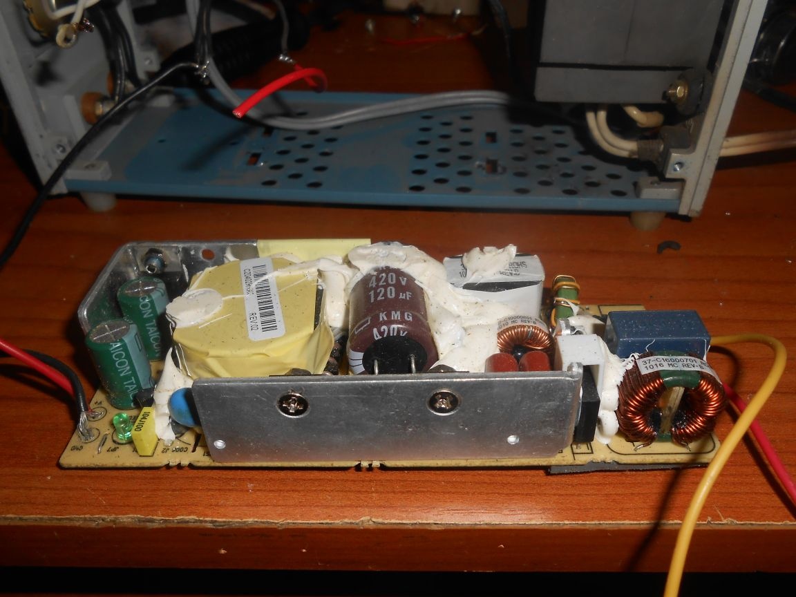
We dismantle all unnecessary:


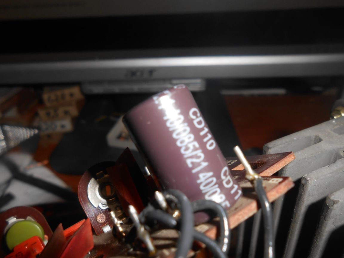
We change the capacitor C5 - 16v 220 mF to the capacitor 2200 mF 25 v (what was)

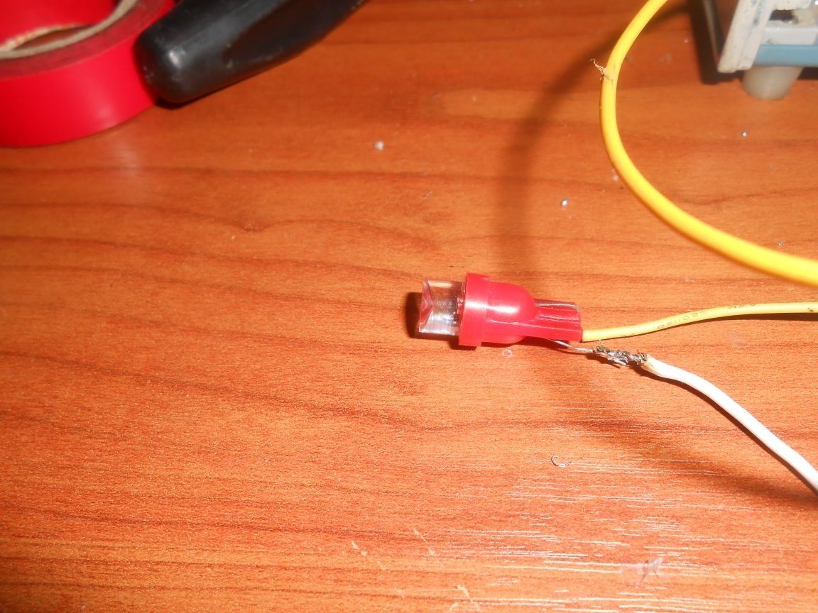
Light bulb 26 V 0.12 A, 3 W

Replace with a LED from the car shop at 12 volts (comes with a limiting resistor, no calculations need to be made).
The LED is connected through the stabilizer L7812, power is supplied from the output.
A cooler is connected to it for cooling


We remove the charger power supply from the case

We are connected to the network from the IPS and the output from the charger (instead of 2 dismantled capacitors, we install one 2200 mF at 25 volts) according to the scheme:

We assemble and adjust
R14 defines the lower output limit
Upper limit set by R9
vt9-r3, r4-CURRENT LIMITER.
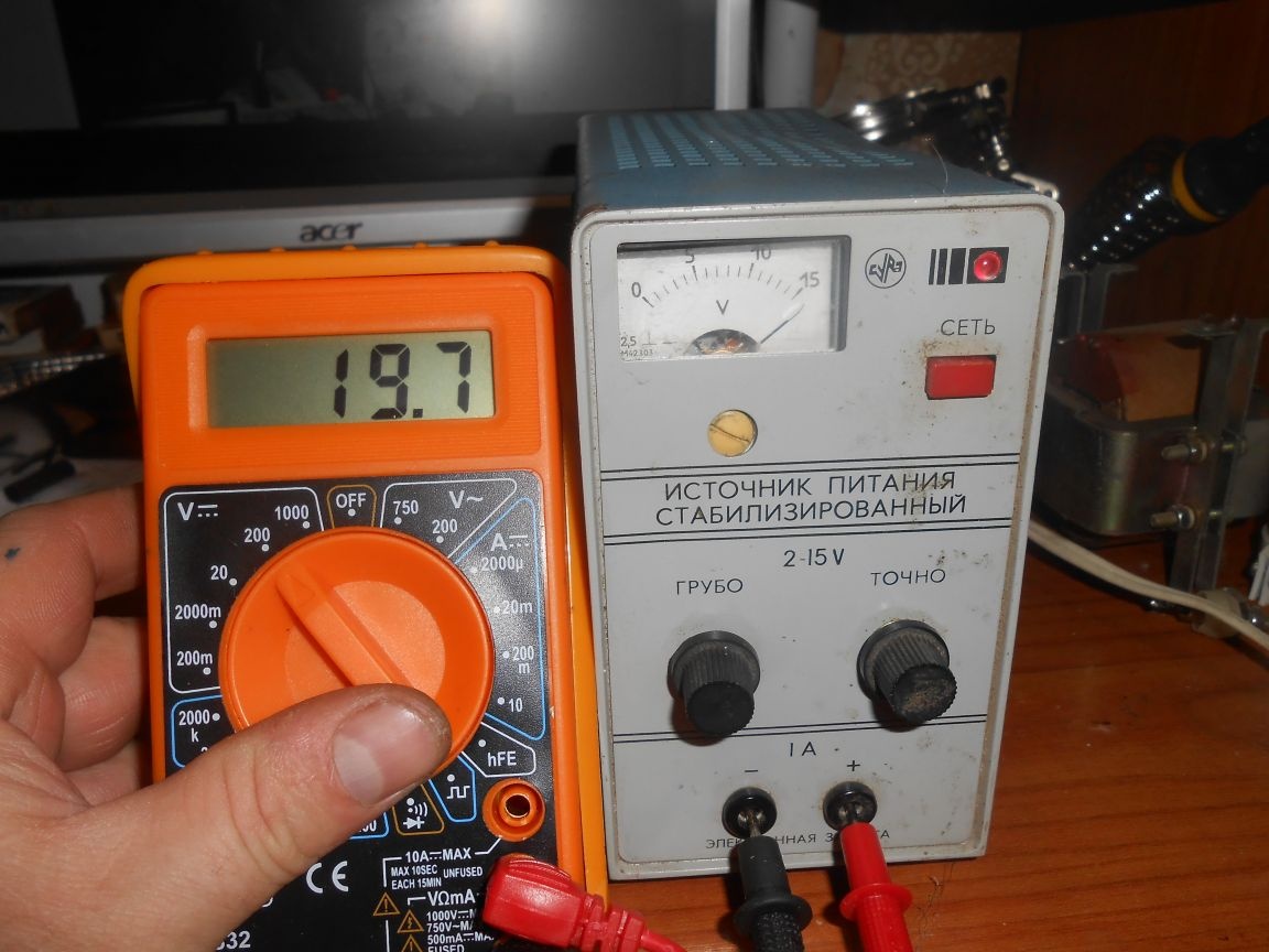
Upper reading limit: 19.7 volts
Lower limit 0 volt

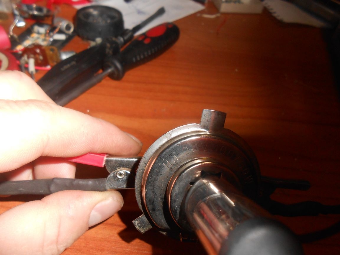
I’m testing an automobile headlight lamp H4 for 24 volts (there is no other at hand ...)


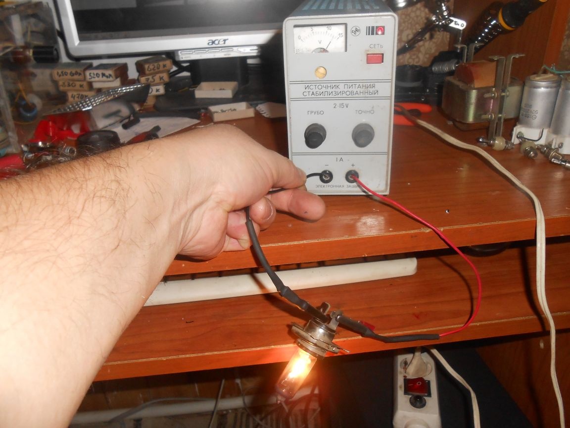
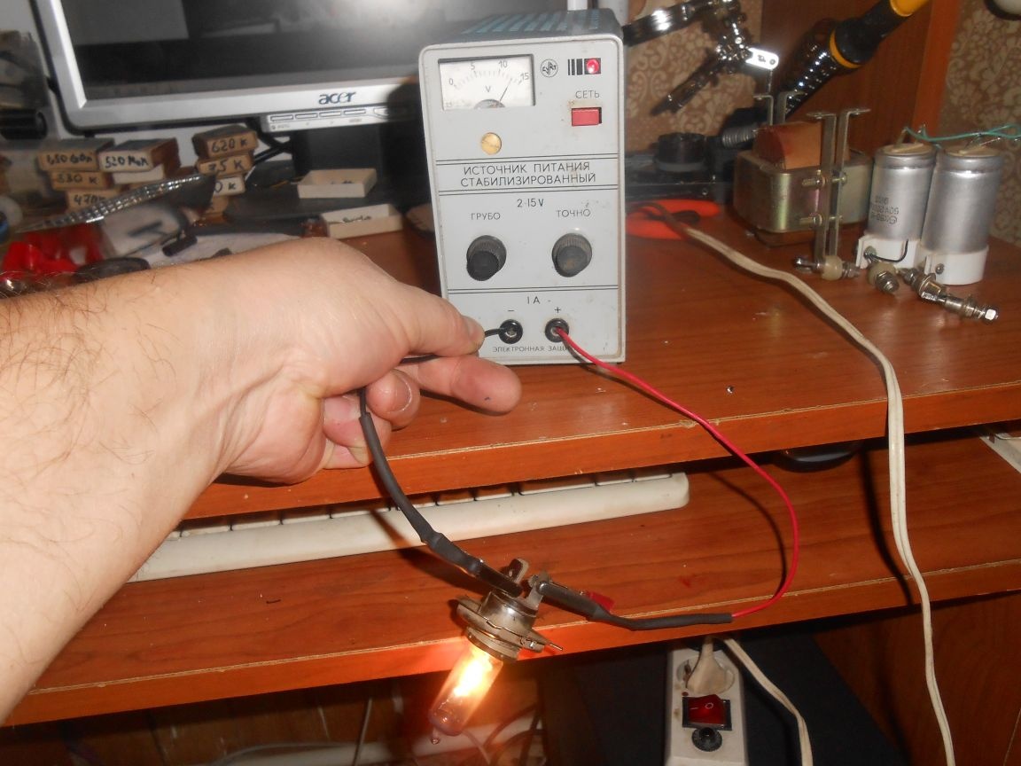
IPS holds 2 amperes without any problems! Check until nothing more.
It remains to wait for the voltmeter ammeter from the Middle Kingdom and the unit will still serve!

The thought came: The current adjustment needs to be brought out, then the 18650 batteries can be charged.
Thanks to all!
6.5
9.3
7.8

Add a comment

    • smilesmilesxaxaokdontknowyahoonea
      bossscratchfoolyesyes-yesaggressivesecret
      sorrydancedance2dance3pardonhelpdrinks
      stopfriendsgoodgoodgoodwhistleswoontongue
      smokeclappingcraydeclarederisivedon-t_mentiondownload
      heatirefullaugh1mdameetingmoskingnegative
      not_ipopcornpunishreadscarescaressearch
      tauntthank_youthisto_clueumnikacuteagree
      badbeeeblack_eyeblum3blushboastboredom
      censoredpleasantrysecret2threatenvictoryyusun_bespectacled
      shokrespektlolprevedwelcomekrutoyya_za
      ya_dobryihelperne_huliganne_othodifludbanclose
22 commentary
Author
Such MLTs will not work, they have a lot of resistance, but you need (in my case) 0.88 Ohms, that is, less than one Ohm. Order in China, there are a bunch of such penny resistors.
Hello, don’t tell me about replacing the resistor, which is indicated on the diagram as R5, of those that I have something that can fit, I just can’t figure it out, because it's not mine.
Author
This is an indicator! I made an auto relay.
Author
The block is compact, just a fairy tale! Holds short circuit 4 amperes without tension.
Author
All ingenious is simple !!! Thanks.
and discharge here is a simple diagram ...
take the chip L200C the circuit in nete is cool itself often soldered it itself controls when charging ... only the radiator is necessary ...
Author
Good evening! Putting a charger for a screwdriver I can’t come up with a discharge control device, not an indicator, cheap and cheerful. Do not tell me the options?
Author
I agree, "put a few resistors inside and switch them," the best option!
Khabibra,
wire rheostat :). Seriously, don’t pull it out. Enough of what is. You can put several resistors inside and switch them. There will be several adjustable thresholds.
Khabibra,
wire rheostat :).
Khabibra,
wire rheostat :). Seriously, don’t pull it out. Enough of what is. You can put several resistors inside and switch them. There will be several adjustable thresholds.
Author
I set R5 0.88 Ohm (protection works less when a 55w light bulb is connected), Amperage when this light bulb is connected, at 12 volts = 4.8 A.
My question is: If R5 is pulled out and made variable to adjust the current, what should be a variable resistor?
The maximum current for KT829 is 8A. If you have 24 V at the input of the power supply, 10 V at the output, then 14 V will fall on the transistor. Now divide 60 W by 14 V and get the maximum current that can be obtained. It will be 4.3 A
There are basic parameters - maximum power dissipated on the collector, maximum voltage on the collector, maximum collector current. Everything else is derived from these parameters. When a voltage of 24 volts is supplied to the collector from a switching power supply and taking into account a saturation voltage of 2 volts, 22 volts with a load current of up to 8 amperes can be obtained at the output. At the same time, a power of 2 volts * 8 amperes = 16 watts will be dissipated on the collector at a maximum permissible 60. The lower the voltage at the output of the power supply (the greater the voltage drop across the transistor), the lower the current power supply can give out. For example, with an output voltage of 2 volts, the maximum current of this power supply is 2.7 amperes. To obtain this parameter, Pmax (60 W) must be divided by Uke (22 V). Hence, Imax = 2.7 A.
And do not go into the graphics. Moreover, the last graph in the figure does not correspond to the parameters printed next to it.
Author
Thanks. For the first time I learned about OBR, I'll take it to mind ... I will (try) to adhere to these parameters (I will write it out, I’ll stick it on BP).
at 10 V (10 V at the PSU output) - 4 A. That is, 4 amperes maximum current for kt829?
OBR is an area of ​​safe operation. It is presented in the parameters of transistors in the form of a diagram
, limiting within itself valid combinations of parameters.
What is OBR? And what are these parameters given?
Do not forget about OBR: at a voltage of KT829 20 V (that is, at 0 at the power supply output) the maximum allowable current is 1 A, at 15 V (5 V at the power supply output) - 2 A, at 10 V (10 V at the power supply output) ) - 4 A.
Will decrease. Only need to experiment. The whole system works like this. Through the parallel connected resistors R3, R4 and R5, the full load current flows. A part of the voltage that is generated on these resistors and applied to the VT9 base is removed from the R4 engine. He begins to open slightly, and after him VT8 opens slightly. He closes VT12 through resistor R2. At the same time, VT13 closes. The output voltage decreases. Hence a simple conclusion - to increase the protection trip current (within reasonable limits), it is necessary to reduce the value of resistor R5. All other elements of the circuit are not related to protection.
Author
Thanks! Today I tested a 12-volt 55W, as an ammeter - a multimeter, readings of 4 amperes, but a drawdown of 3 volts ... If you replace the R5 with 0.33 Ohm according to your advice, will the drawdown decrease?
The idea is great, the performance is wonderful. Given that the maximum dissipated power on the KT829V collector is 60 W and the maximum constant collector current is 8 A, it is possible to increase the output current to 3-3.5 A by reducing the R5 rating to 0.33 Ohms and increasing its power to 5 watts.
Good luck

We advise you to read:

Hand it for the smartphone ...