When designing a small machine for processing glass edges, in full growth, the task arose of supplying water to a diamond tool. Cooling, flushing glass dust. Water consumption is very small, the lift height is also not great - a maximum of several tens of centimeters. If possible, a convenient and reliable pump design, a minimum of additional space, a collapsible design.
In factory analogues, the water supply is carried out by an impromptu pump, structurally combined with the tool motor-drive shaft.
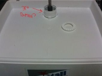
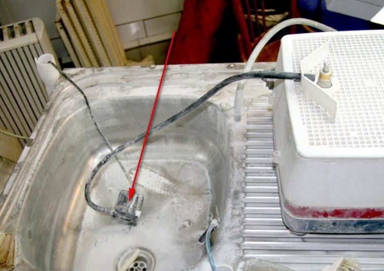
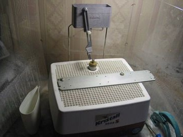
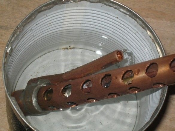
In the picture, the grinding machine is popular among stained glass artists and among amateur "glassmaking". There are several analogues, but they do not differ significantly. Sorry for the signatures, the photo was taken from some kind of glass forum. And yes, it’s a pump. Motor under the trough. Water is poured into the trough, on top of the trough is a lattice-desktop. Rotating the shaft (~ 3000 rpm) with the help of that ribbed ring, he spits out water on a working tool - a diamond cutter-cutter.
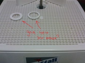
These rings, it seems, for a rough adjustment of the performance of the pump.
The water supply scheme of a separate pump is also used, for example.
A separate pump from an aquarium or a fountain, a separate water tank is a regular trough of not great depth and nothing serious, just does not fit. Here, you have to organize a drain from the standard capacity.
Finally, the most sophisticated way to supply water, by gravity from an upstream tank. And it seems that the factory design. You should also think about organizing a drain from the standard capacity or limit the capacity of the "tank" and flop here and there with a mug.
Let's start - at first, several attempts were made to apply a water supply with the “Air Lift” design, as the bourgeois call it. The idea attracted by the absence of moving parts under water, low dirt requirements, simple design. However, a decent result was never achieved, and the retro aquarium compressor was broken. There was no point in acquiring a new one; I had to turn to the classic “centrifugal fan” design.
Pumps of a similar design, in assortment are presented among homemade. Basically, these are structures made of electric micromotors and a plastic “snail” with an impeller. Installation with superglue or hot glue from a gun.
When designing his pump, it was decided to use the glands, connect by soldering. Move the engine out of the water and transmit the torque using an elongated shaft. Also, if possible, avoid "sticking" of the outlet pipe sideways, for compactness, even if this slightly reduces the efficiency of the pump.
So. What was used.
Instruments.
A set of small metalwork tools. Small vise. Needle files. Engraver. Something to drill. For even edges of the cut of the copper tube, it is convenient to use a special cutter with wheels, such are used when installing copper water pipes. I used a soldering iron with a power of about 60 watts with accessories, a small gas torch for soldering. A jewelry jigsaw came in handy. It is convenient to use an electric sharpener with a “stone” of medium grain size.
Materials
A suitable motor, glands from the water supply, which are made of copper or its alloys - used a copper tube with a diameter of 15 mm, 6 mm. Inside from the old tap, copper wire from wire and cable, thick brass foil. Solder and flux for "burner" soldering (also from a copper water supply), grinding skin.
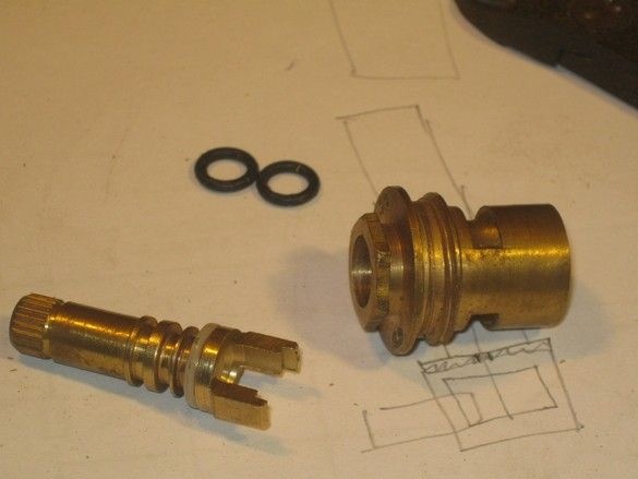
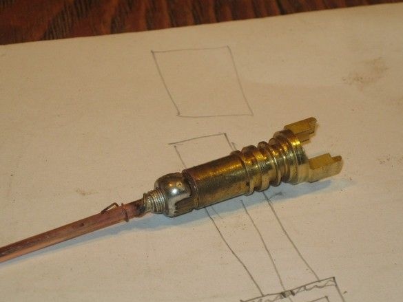
The pump itself, it was decided to perform from an unusable crane. It was attracted by a rather tight fit of the shaft in the housing, relevant dimensions, material. The crane was disassembled, the stopper, rubber gaskets, and ceramic elements were removed.
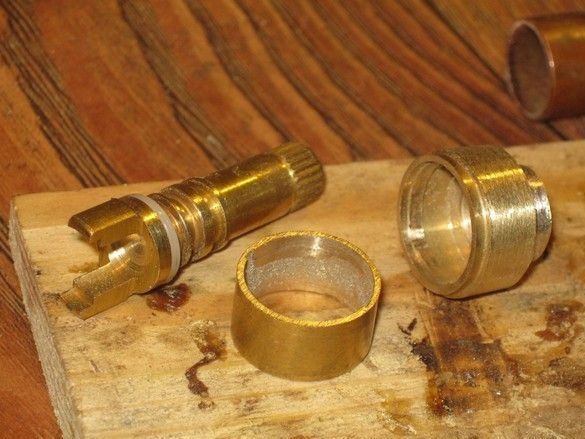
The body is turned on an electric grinder, shortened. Using a drill with an abrasive nozzle, two stops were removed allowing the shaft to turn only half a turn.
The long shaft from the electric motor is made of thick wire with mono core. It is sealed in the pump shaft, the thickness of the extension shaft at the soldering point is increased by two layers of tinned copper wire winding.
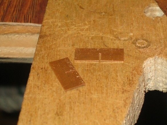
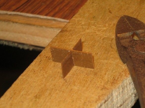
The “wings” of the pump are made of a thick copper plate. Cut with scissors for metal. Saws made by jewelry jigsaw. Two sawed next.
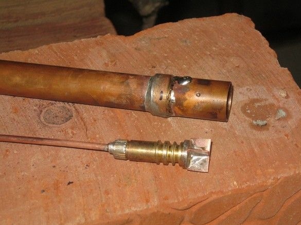
The blades are soldered into place, their length is specified. A long tube 15 mm in diameter is soldered to the pump casing. The bottom case is elongated with a suitable piece of copper pipe.
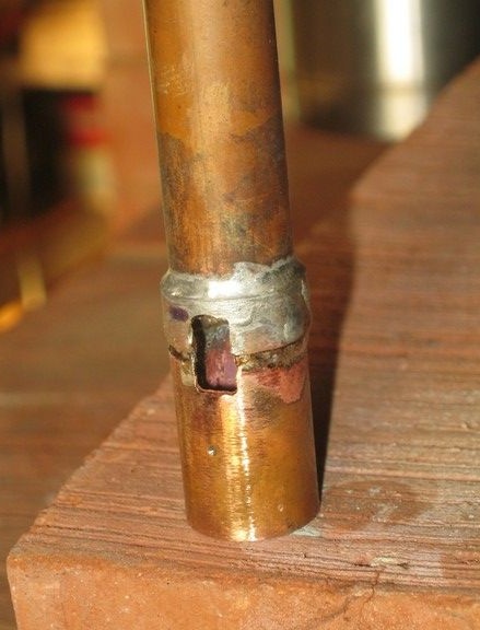
Opposite the impeller blades, a rectangular opening is cut. Let me remind you, it was decided not to apply a tangential retraction, for the sake of a more compact layout.
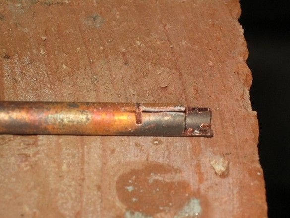
Billet of the outlet pipe from a copper tube with a diameter of 6 mm, a hacksaw for metal cuts are made to form a knot that fits tightly with the window in the pump housing. The end of the workpiece is annealed in the flame of a gas burner.
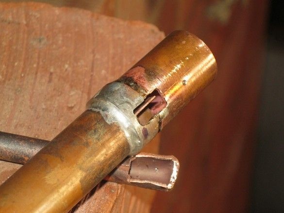
Formed chamber turning into the outlet pipe, adjusted to the place of soldering. The impeller blades are visible in the pump housing window.
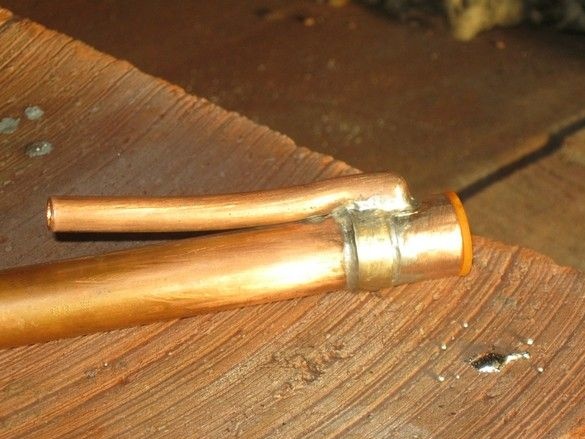
The pipe was soldered, the place of soldering was sawn off from excess solder streaks - it was necessary to solder very carefully so that everything else would not fall off. The pipe is shortened.
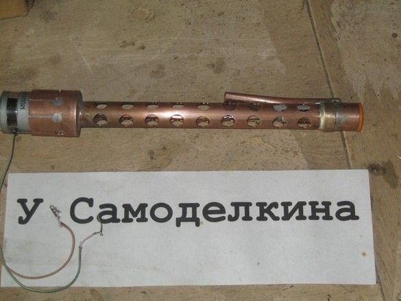
The rod on which the motor seat will be, was marked and drilled a bunch of holes. Reminds a casing at PPSh.
The motor was selected - DPM-25 – H1-04 (27 Volts, 2500 rpm, 220 mA). There were no elements like a flange for mounting on the motor, it was decided to fix it with a collet. For its manufacture, on lathe the equipment was machined - a wooden block of birch, its diameter is equal to the diameter of the motor, on it (on the block) I will bend a copper cup.
For the details of the collet, there was no copper or alloy of suitable thickness, it was necessary to cut a piece of the copper tube, saw it along, anneal, straighten, straighten. From such a blank, in the photo, the future bottom of the grip. The inner hole is cut with a jewelry jigsaw.
Future collet before soldering with a burner. Despite annealing, the glass tried to straighten up a bit, I had to fix it and solder it directly on the snap. So that the piece of wood does not burn, she does not get the centimeters to the bottom.
The cup after soldering is shortened, the holes of the collet itself are marked, drilled. Hacksaws made for metal cuts. The blank was neatly fastened in a vice with an inserted block, sawed directly on the block, it was not a pity.Then everything was sanded, protruding from the bottom plate roughly cut with scissors for metal, finally finished on the grinder.
Soldered the finished collet to the pump rod. The collet petals will be compressed with a hose clamp, such as those that fix the irrigation hoses to the taps. With a worm screw. It is only necessary to choose the option of stainless steel - galvanized with copper will create a galvanic pair.
An “extension cord" was soldered to the motor shaft from the same copper wire, at its end perpendicular to the axis, a hole 1.5 mm in diameter was drilled and a piece of tinned copper wire was soldered into it. The pump shaft has a corresponding seat at the end. The coupling allows the structure to be disassembled for cleaning or repair.
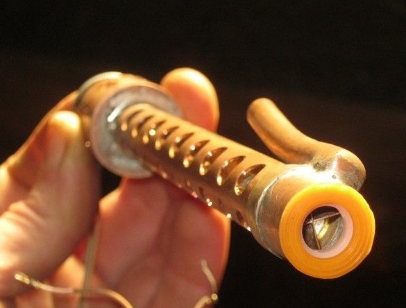
The clutch in the working position, after installation "on the site", will be fixed by a segment of the heat pipe.
Pump assembly. Rubber plug - a part from the crane from which the pump body is machined.
Test. The motor is powered by a small 12 V power supply. Despite the power supply being less than half of the rated power, the pump works. At the workplace, he will have to provide a pole at least twice as high with the same performance, this will be easy to do, by slightly increasing the power. The low voltage of the motor will also allow for convenient adjustment of pump performance. Smooth - adjustable stabilizer, although for practice, 3 ... 5 taps from the secondary winding of the transformer and rectifier should be enough.