

With the spread of the Internet, amateur radio, no matter how sorry, it gradually began to fade. Where did the army of radio hooligans go, the legions of "fox hunters" with direction finders, and their other colleagues ... Canuli, there were crumbs left. There is no mass agitation at the state level and in general, the system of values has changed - young people often prefer to choose other entertainments for themselves. Of course, Morse code is not often used in the current digital age and radio communication in its original form is increasingly losing its position. However, amateur radio as a hobby is a mixture of a sort of romance of wanderings with considerable skills and knowledge. And the ability to creak your brains, and put your hands, and the soul to rejoice.
However, to the point. So.
When choosing a design for repetition, there were several requirements arising from my initial knowledge in the field of designing RF equipment - the most detailed description, especially in the sense of tuning, the absence of the need for special RF measuring instruments, an accessible element base. The choice fell on the direct conversion transformer Victor Timofeevich Polyakov.
- communication equipment, radio station. The receiver and transmitter in one bottle, and part of the cascades they have in common.
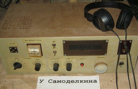
SSB transceiver entry-level, single-band, at a range of 160m, direct conversion, tube output stage, 5 watts. There is a built-in matching device for working with antennas of various wave impedances.
- single-band modulation (Amplitude modulation with one sideband, from the English Single-sideband modulation, SSB) - a type of amplitude modulation (AM), widely used in transceiver equipment for the effective use of the channel spectrum and the power of the transmitting radio equipment.
The direct conversion principle for obtaining a single-band signal allows, among other things, to do without specific radio elements inherent in a superheterodyne circuit - electromechanical or quartz filters. The 160m range for which the transceiver is designed can be easily changed to a range of 80m or 40m by reconfiguring the oscillating circuits. The output stage on the radio tube does not contain expensive and rare RF transistors, is not picky about the load and is not prone to self-excitation.
Take a look at the circuit diagram of the device.
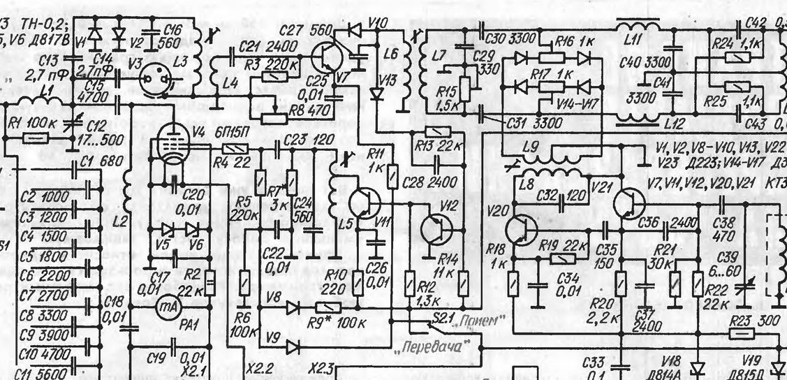
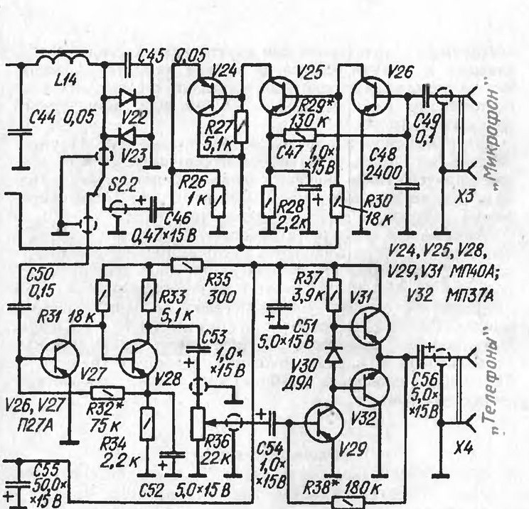
A detailed analysis of the circuit can be found in the author’s book [1], there is also an author’s printed circuit board, transceiver layout and a sketch of the case.
Compared with the author’s design, the following changes have been made in their execution. First of all, the layout.
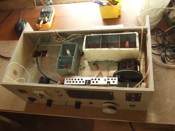
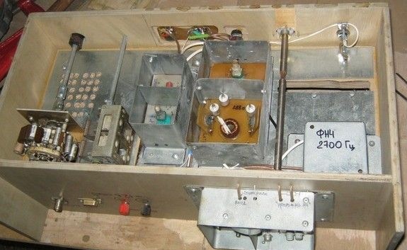
The transceiver version is designed to operate on the lowest frequency amateur range, it allows for a "low-frequency" layout. In their own performance, solutions were used that are more applicable to RF equipment, in particular, each logically complete unit was located in a separate shielded module. Among other things, it makes it much easier to improve the device. Well, I was encouraged by the possibility of a simple readjustment to 80, or even 40m ranges. There, such a layout would be more appropriate.
The transmission-reception toggle switch has been replaced by several relays. Partly because of the desire to control these modes from the remote button on the sole of the microphone, partly by more correctly wiring the signal circuits - now they did not need to be dragged from afar to the toggle switch on the front panel (each relay was at the switching point).
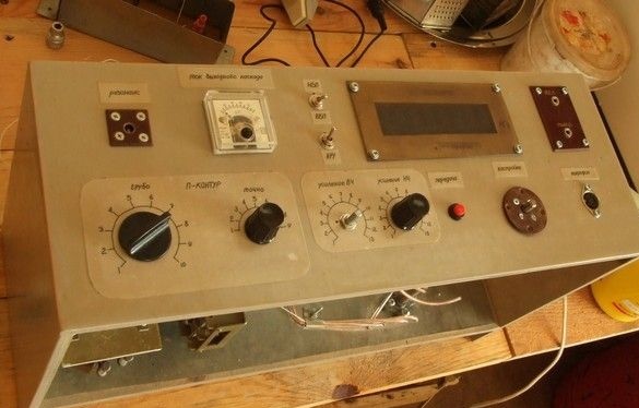
In the design of the transceiver introduced vernier with great slowdown and digital scale, this makes it much more convenient to tune to the desired station.
What was used.
Instruments.
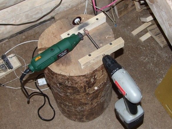
Soldering iron with accessories, a tool for radio installation and a small metalwork. Scissors for metal. A simple carpentry tool. Used a milling machine. Useful rivets with special pliers for their installation. Something for drilling, including holes on the printed circuit board (~ 0.8 mm), can be contrived with one screwdriver - the handkerchiefs are specific, there are few holes. Engraver with accessories, hot melt glue gun. It’s good if you have a computer with a printer at hand.
Materials
In addition to radio elements - mounting wire, galvanized steel, a piece of organic glass, foil material and chemicals for the manufacture of printed circuit boards, related items. Thick plywood for the case, small cloves, carpentry glue, a lot of skins, paint, varnish. A bit of polyurethane foam, a thick dense polystyrene foam - “Penoplex” 20 mm thick - for thermal insulation of some cascades.
First of all, in AutoCAD, the layout was drawn, as the whole device, and each module.
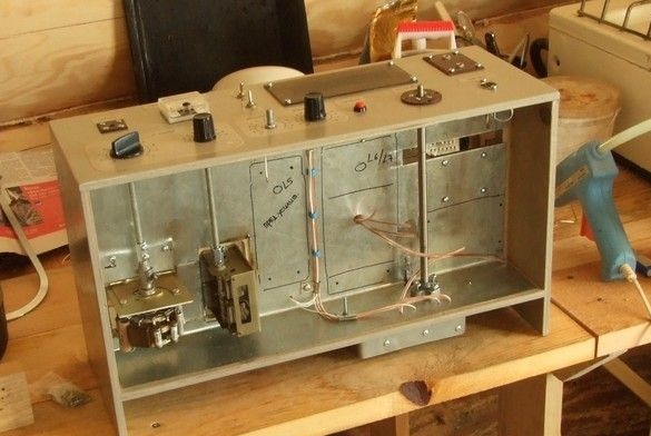
The modules themselves were made - printed circuit boards, "nests" of the module housings made of galvanized steel. Boards are assembled, contour coils are wound and installed, boards are soldered into individual casing shields.
Variable capacitor for local oscillator - with every other plate removed. I had to disassemble and solder the stator blocks, then put everything in place.
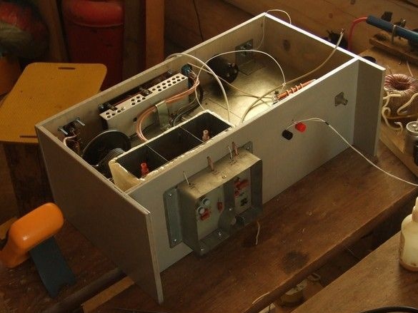
The case is made of 8 mm plywood, after fitting the openings and holes, the box is sanded and covered with two layers of gray paint. Inside, the box is finished with the same galvanized steel and the final installation of elements and modules has begun.
The wiring switch and the variable capacitor of the matching device are located near the antenna connector, this allows to shorten the connecting wires as much as possible. To control them from the front panel, extensions of their shafts from 6mm threaded rods and connecting nuts with stoppers are used.
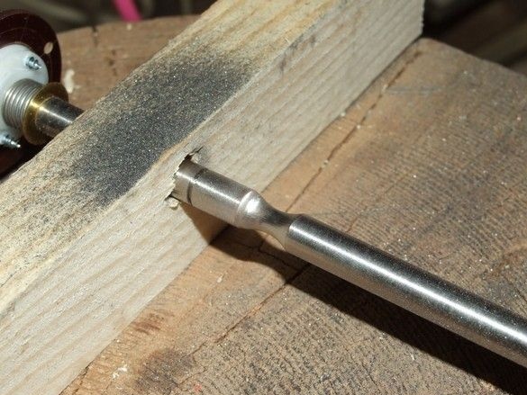
The axis of the configuration verniere is made of a shaft from a broken inkjet printer, on the same axis there was a braking unit, which was also useful. The groove holding the vertical cable is made using an engraver.
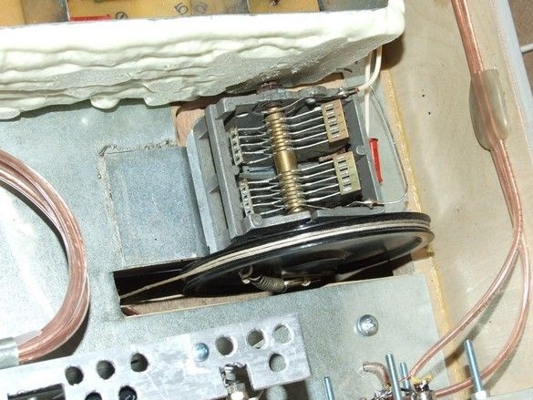
A special pulley, the cable itself and a spring providing a preload are taken from the tube radio.
The tuning knob is made of two large gears from the same printer. The space between them is filled with hot melt adhesive.
The walls of the local oscillator module are trimmed with a layer of mounting foam, this allows to reduce the “frequency drift” due to heating when tuning to the station.
The telephone and microphone amplifier module is placed on the rear wall of the housing, for its (module) protection against mechanical damage, releases are made on the side walls of the housing.
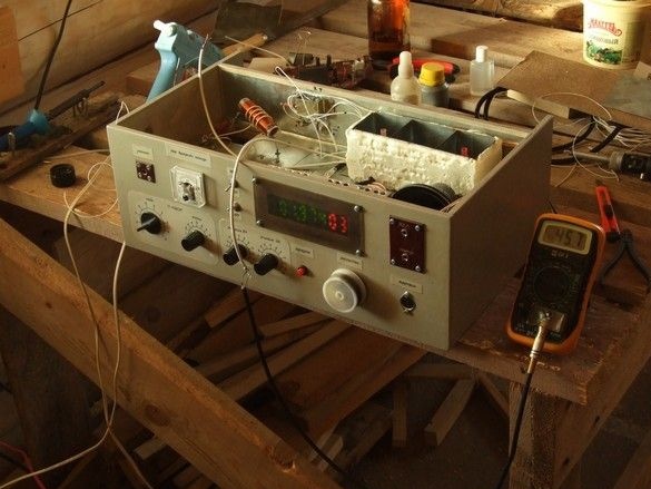
Setting the local oscillator transceiver. For her, a simple RF prefix to a multimeter was made, which makes it possible to assess the level of RF voltage, for example [2].
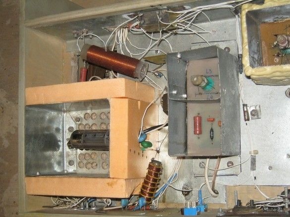
Initially, it was decided to change the scheme of the output stage of the transmitter to a semiconductor one, powered by the same 12 V. In the photo above, it is not up to the end that it is assembled - a milliammeter for higher current, an additional winding on the P-loop coil, only low-voltage power.
Scheme of changes. The output power is about 0.5 watts.
In the future, it was decided to return to the original. I had to replace the milliammeter with a more sensitive one, add the missing elements, change the power supply.
The power amplifier module is thermally insulated from other structural elements, as it is a source of a large amount of heat. Its natural ventilation was organized - a field of holes was made in the basement of the housing and on the lid above the module.
The basement of the hull also contains a number of blocks and modules.
The transceiver circuit has the simplest solutions for individual nodes and does not shine with characteristics, however, there are a number of improvements and improvements aimed both at improving the performance characteristics and increasing the convenience during work. This is the introduction of switching the side bands of the signal, automatic gain control, the introduction of the telegraph mode during transmission. The suppression of a non-working sideband can also be slightly increased by reducing the dispersion of the characteristics of the mixer diodes, for example, by using instead of the diodes V14 ... V17 the diode assembly of KDS 523B. Improvement of individual nodes can be performed according to the schemes of [1]. It is also worth paying attention to solutions [3]. The applied layout allows you to do this quite conveniently.
Literature.
1. V.T. POLYAKOV. DIRECT TRANSFERS Transceivers Publishing House DOSAAF USSR. 1984 year
2. Scheme of the prefix to the multimeter for measuring the RF.
3. Dylda Sergey Grigorievich. Low signal path SSB TRX’a direct conversion to a range of 80m
Additional materials.