

I want to collect do it yourself instrument that will measure atmospheric pressure and temperature. The temperature sensor must be remote and tight, as it must measure the temperature at a certain distance from the device. I would like to have such a portable device with a working range from -30 ° C to 50 ° C. But this requires that all components be able to work in this temperature range. Components that can work in an extended temperature range are more expensive, and it’s more difficult to buy them.
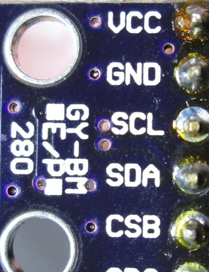
To fulfill my dream into reality, I will be helped by the board, which I described in the article “GY-BMP280-3.3 board for measuring barometric pressure and temperature».
From practice, it is known that during assembly and configuration electronic products before its manufacture, you need to check the serviceability of all materials and components of each separately. Otherwise, you can get confused later, and as a result, the electronic product will not work, and it will be very difficult to find the cause of the malfunction.
Let's get started.
First stage. Install a free software shell on your computer Arduino IDE for writing programs (sketches), compiling them and then writing them to the Mega328P microcontroller installed on the board. I recommend you download the shell version of ARDUINO 1.6.5. Why? Initially, the ARDUINO project was one, now the developers have dispersed and continue to develop the ARDUINO system, but each in its own way, with small nuances. I used version ARDUINO 1.6.5. It should be installed and tested for collaboration with the Arduino Uno board using the simplest examples.
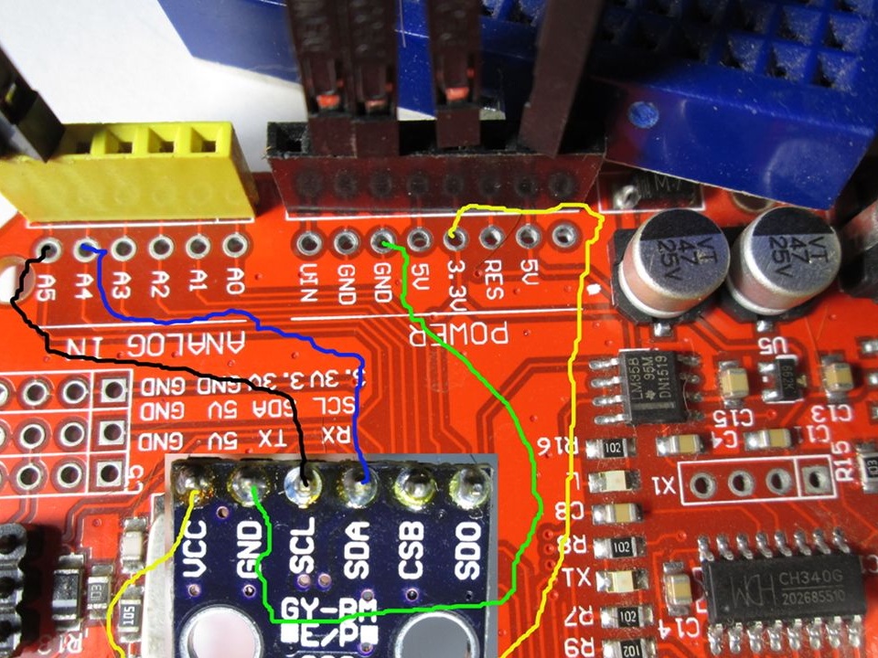
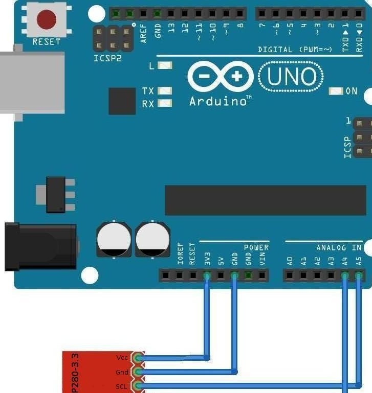
Second phase. We check the GY-BMP280-3.3 board for measuring barometric pressure and temperature. We take 4 wires, we connect them GY-BMP280-3.3 and Arduino Uno, as shown in the photo and diagram. Curves thin multi-colored lines are conductors.
Let's start checking the GY-BMP280-3.3 board. To do this, you need to install the library in the Arduino IDE, written by programmers working on the site. As a rule, after installing the library in the Arduino IDE, examples (samples) of code appear. By slightly changing the sample code, we can compile it into data that is understandable to the microcontroller, and then send it to the memory of the microcontroller. You can find an example (sample) by paying attention to the two screen photos below.
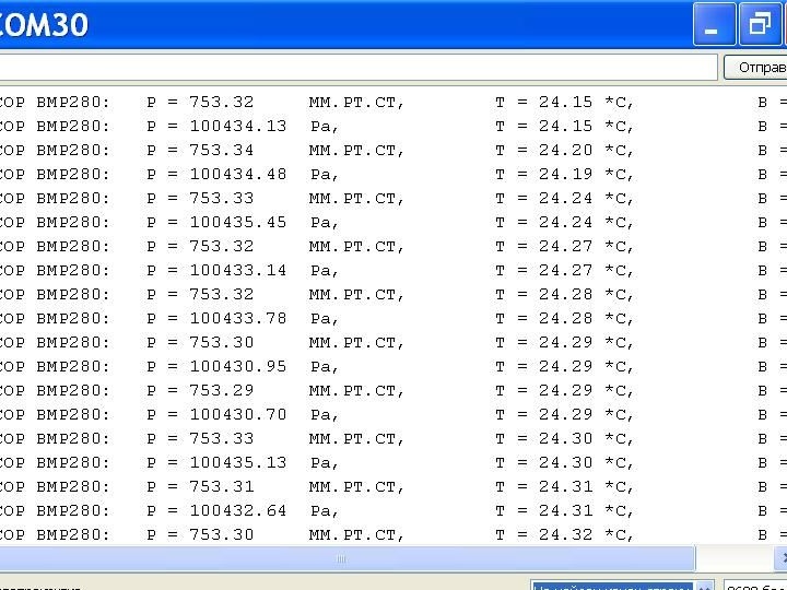
After writing data to the microcontroller of the Arduino Uno board, it immediately starts executing the program (code) and sends the data via USB cable to the computer to which the Arduino Uno board is connected.And we can see the measurement result of the GY-BMP280-3.3 board in the Arduino IDE window, called the “serial port monitor”.
We can see the result of measurements on the GY-BMP280-3.3 board in the standard Windows Hyper Terminal program, after closing the Arduino Uno shell and setting up a session in the Hyper Terminal program. That is, we can get the results of the GY-BMP280-3.3 board by connecting the Arduino Uno to any computer with a USB cable on which the driver for the Arduino Uno board is installed. There are several libraries for working with GY-BMP280-3.3. Everything worked for me with the library. The file that you download from this site will look like this: bd7e4a37c1f4dba2ebde9b9cd49f45ce.zip. It needs to be renamed as: iarduino_Pressure_BMP.zip. Now we need to install the iarduino_Pressure_BMP library in the Arduino IDE shell.
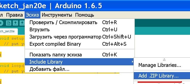
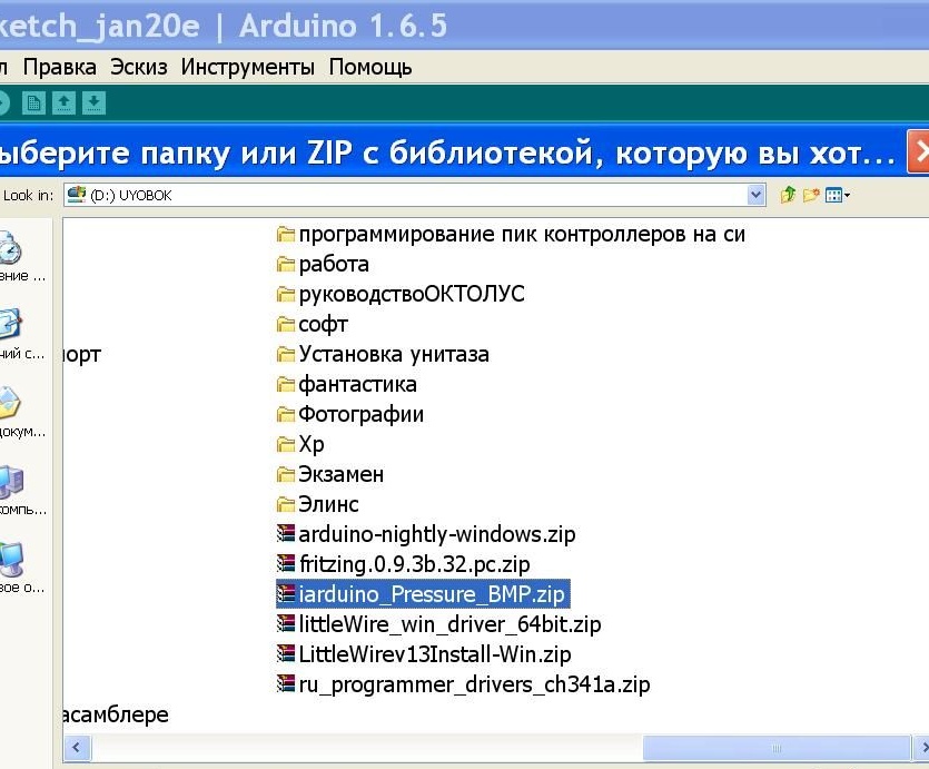
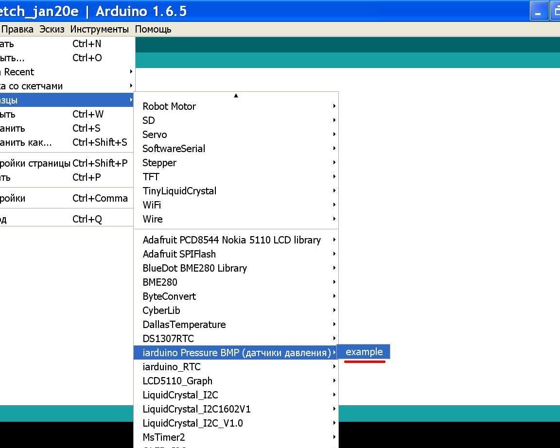
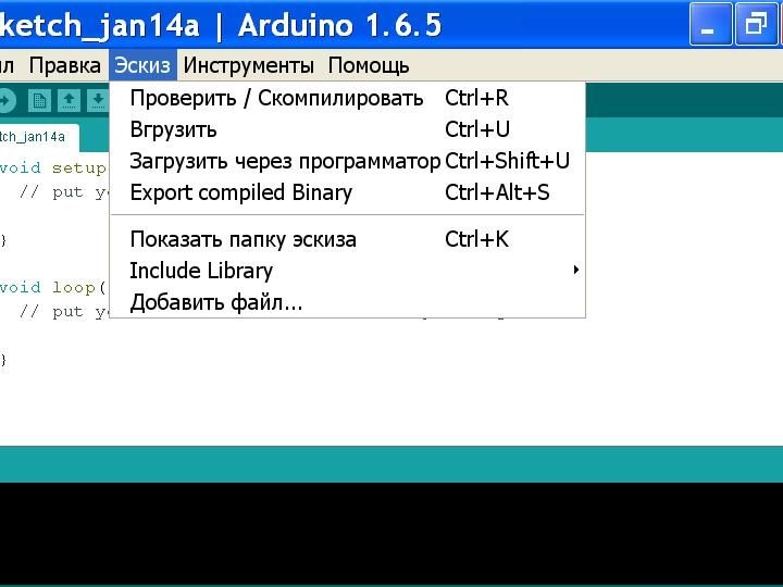
Launch the Arduino IDE, go to the Sketch / Include Librari / Add.ZIP Library menu ... then select the iarduino_Pressure_BMP.zip file and click the Open button. You also need to install the libraries:,. After installing the libraries, we reboot the Arduino IDE shell, that is, close it and start it again. Then select the menu File / Samples / iarduino Pressure BMP (pressure sensors) / example.
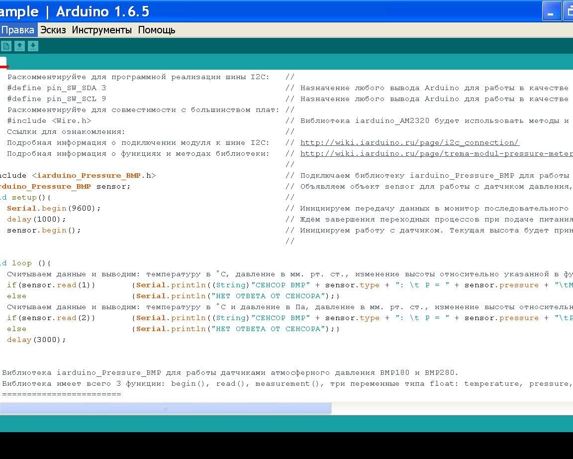
We see the code in the window.
The code will need to be slightly modified.
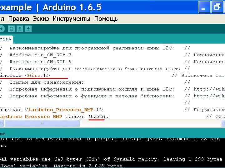
In the fifth line, remove two slashes “//” and add (0x76) or (0x77) in the eleventh line. (0x76) is the address of the barometer board. My GY-BMP280-3.3 board connected to the I2C bus turned out to have the same address (0x76). How to find out the number of the device connected to the I2C bus? You will get the answer to this question by reading the full article.
So, we fixed the code in the window, now we start checking and compiling the code in the menu Sketch / Check / Compile. If the verification and compilation of the code is successful, then in the Sketch / Load menu, we start the program recording in Arduino Uno.
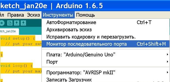
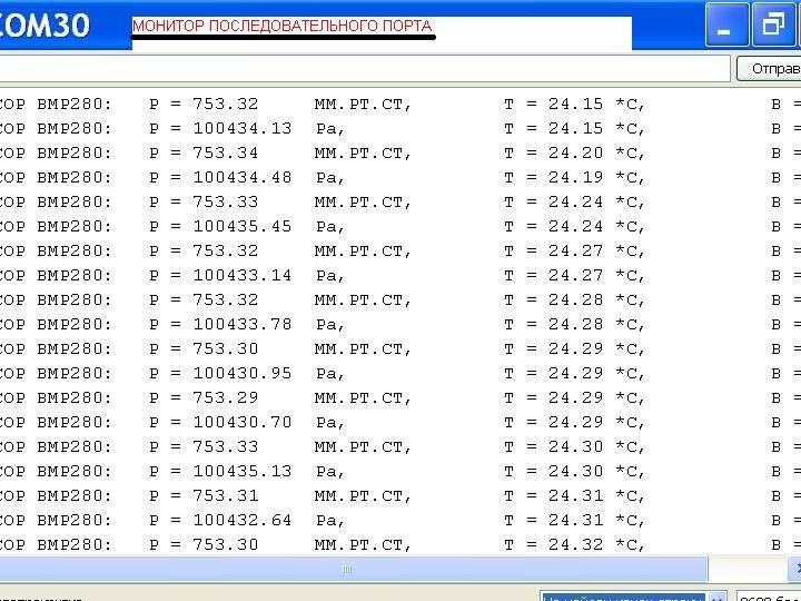
If the download is successful, then by opening the serial port monitor in the menu: Tools / Serial Port Monitor, we will see the data sent by the GY-BMP280-3.3 board.
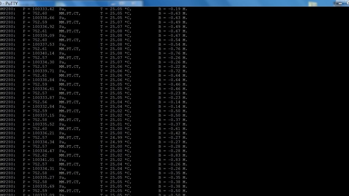
In the following screenshot, the result of the GY-BMP280-3.3 board working on a computer on which the Arduino IDE shell is not installed. The data is received by the PuTTY program.
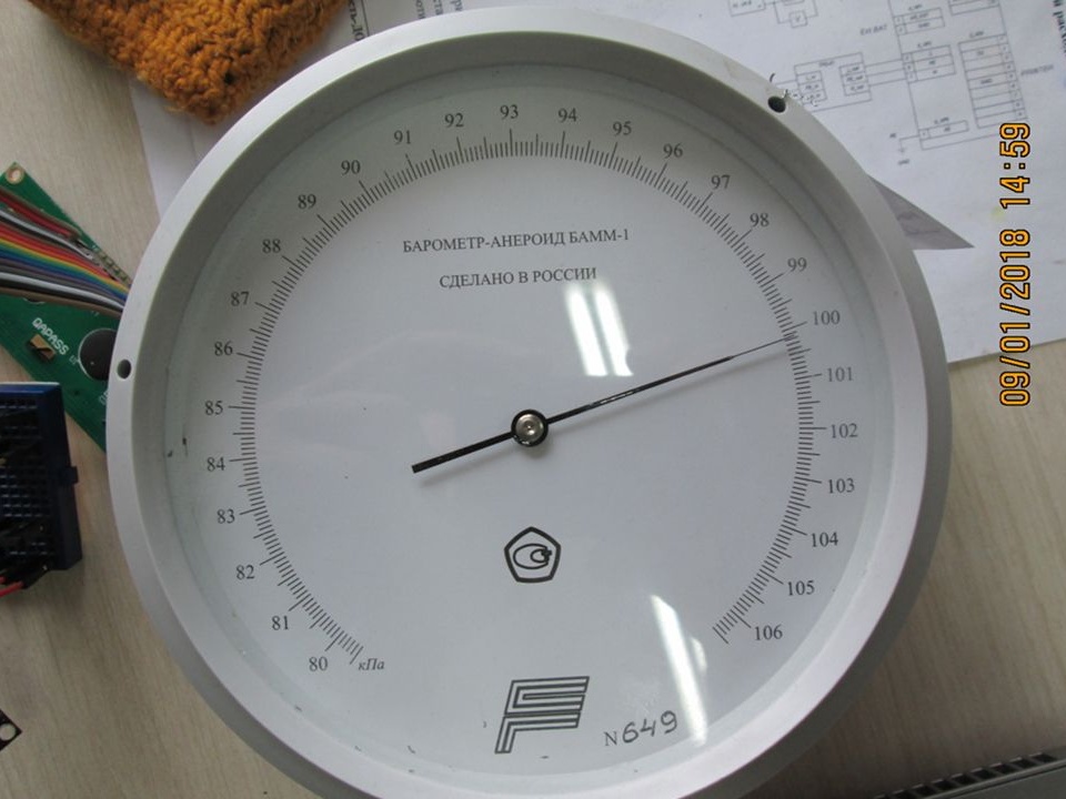
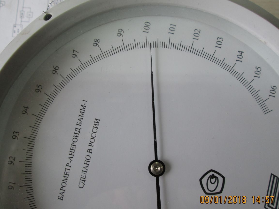
At the same time, a laboratory aneroid barometer was photographed, which was located next to the GY-BMP280-3.3 board. By comparing the instrument readings, you yourself can draw conclusions about the accuracy of the GY-BMP280-3.3 board. Aneroid barometer certified by state laboratory.
Third stage. Checking the LCD display with the I2C interface module. We find an LDC display with an interface module that connects via the I2C bus to the Arduino UNO.
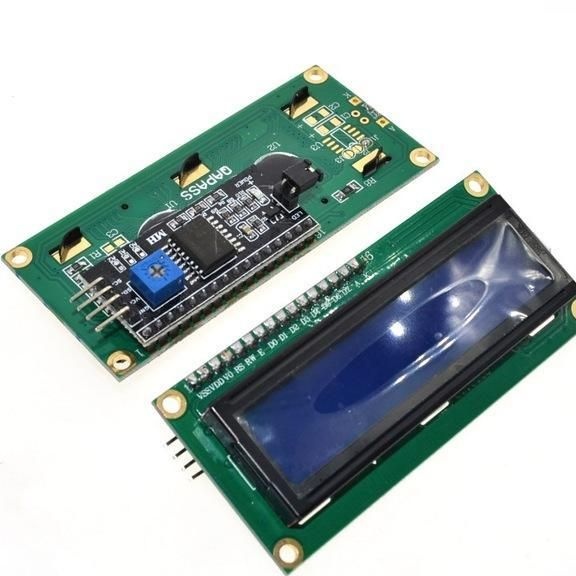
We check its operation using examples from the Arduino IDE shell. But before that, we determine the address of the interface module. My interface module has an address of 0x3F. I inserted this address into the sketch line: LiquidCrystal_I2C lcd (0x3F, 16.2);
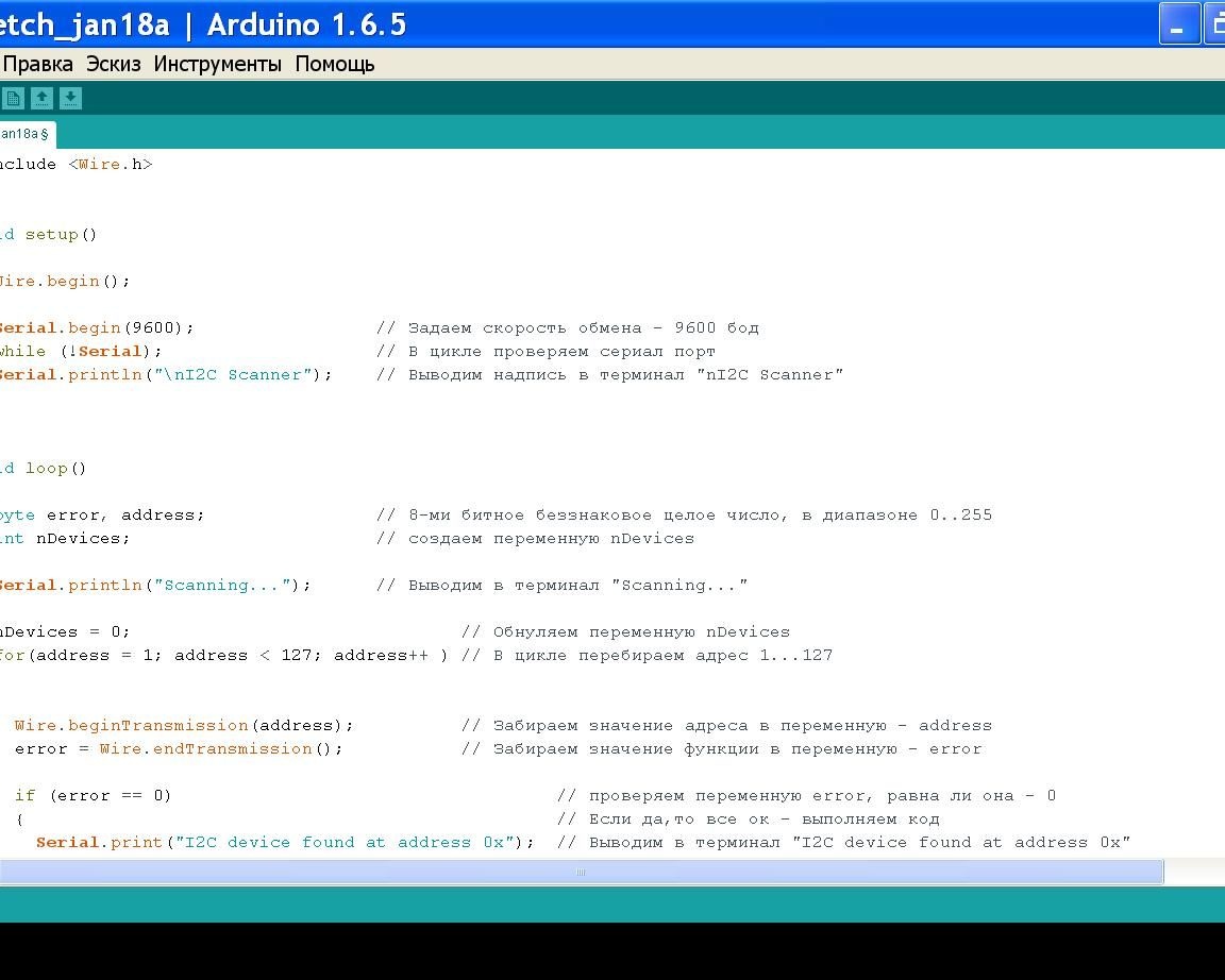
I determined this address using the “I2C device address scanner” sketch described in.
I launched the Arduino IDE shell, from the article I copied the program code and pasted its Arduino IDE window.
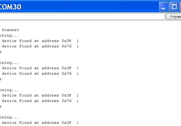
I started the compilation, then wrote the code into the Arduino UNO board, to which the GY-BMP280-3.3 board and the LDC display with the I2C interface module were connected. Then in the serial port monitor I got the following result. My interface module has an address of 0x3F.
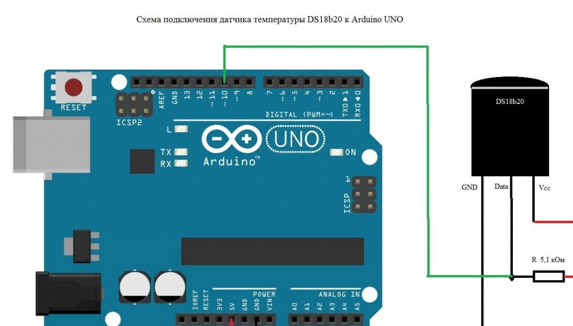
Fourth stage. Checking the DS18b20 temperature sensor. We connect it as follows.
The OneWire Arduino Library for working with the DS18b20 temperature sensor is already installed.
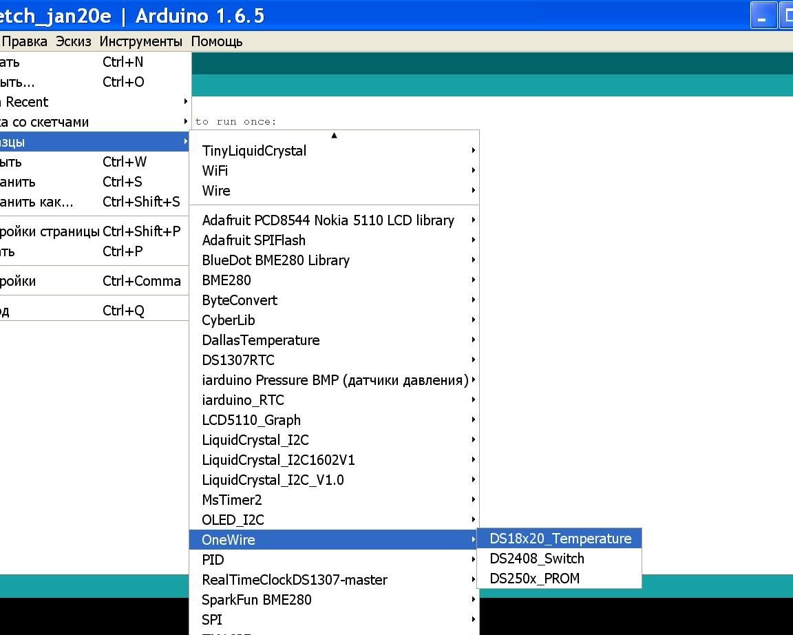
Open the DS18x20_Temperature sample, compile, load, watch the measurement result in the serial port monitor. If everything works, proceed to the next step.
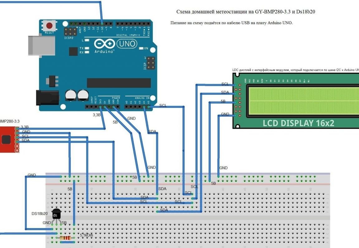
Fifth stage. Assembly home weather stations on the GY-BMP280-3.3 and Ds18b20.
We assemble the device according to the scheme:
I received the code for the device by combining all the examples into one and setting the output on the LDC display screen. That's what I did:
// Uncomment for a software implementation of the I2C bus: //
// #define pin_SW_SDA 3 // Assign any Arduino pin to work as an SDA line of the I2C software bus.
// #define pin_SW_SCL 9 // Assign any Arduino pin to operate as an SCL line to the I2C software bus.
// Uncomment for compatibility with most boards: //
#include
#include // The iarduino library will use the methods and functions of the Wire library.
#include // Library for working LDC type 1602 on the I2C bus
//
#include // Connect the iarduino_Pressure_BMP library to work with BMP180 or BMP280.
iarduino_Pressure_BMP sensor (0x76); // Declare a sensor object for working with a pressure sensor using the functions and methods of the iarduino_Pressure_BMP library.
LiquidCrystal_I2C lcd (0x3F, 16.2);
OneWire ds (10);
void setup () {
lcd.init ();
lcd.backlight ();
Serial.begin (9600); // Initiate data transfer to the serial port monitor at 9600 baud.
delay (1000); // We are waiting for the completion of transients when applying power
sensor.begin (73); // Initiate work with the sensor. The current altitude will be taken as 73 m. - the height of the city of Buzuluk above sea level
} //
void loop () {
// Read the data and display: temperature in ° C, pressure in mm. rt., change in height relative to the specified in the begin function (default 0 meters).
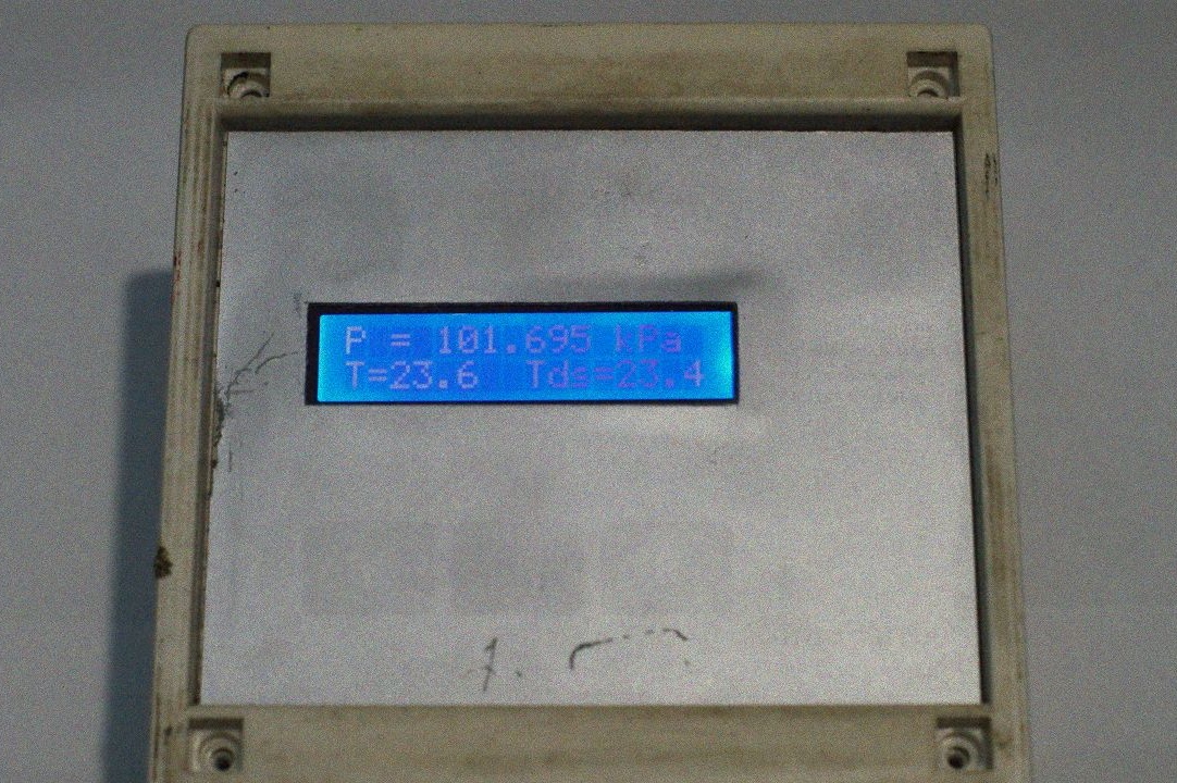
lcd.setCursor (0,0); // define the output point "P =" on the LDC
lcd.print ("P =");
lcd.print (sensor.pressure / 1000.3); // divide the value of P issued by BMP280 by 1000 and set the output of 3 decimal places
lcd.setCursor (12.0); // define the output point "kPa" on the LDC
lcd.print ("kPa");
lcd.setCursor (0,1);
lcd.print ("T =");
lcd.print (sensor.temperature, 1); // set the output of 1 decimal place
lcd.setCursor (6.1);
// lcd.print ("C");
// lcd.setCursor (9,1);
// lcd.print ("H =");
// lcd.print (sensor.altitude, 1);
if (sensor.read (1)) {Serial.println ((String) "CEHCOP BMP" + sensor.type + ": \ t P =" + sensor.pressure + "\ tMM.PT.CT, \ t T = "+ sensor.temperature +" * C, \ t \ t B = "+ sensor.altitude +" M. ");}
else {Serial.println ("HET OTBETA OT CEHCOPA");}
// Read the data and display: temperature in ° C and pressure in Pa, pressure in mm. rt., change in height relative to the specified in the begin function (default 0 meters).
if (sensor.read (2)) {Serial.println ((String) "CEHCOP BMP" + sensor.type + ": \ t P =" + sensor.pressure + "\ tPa, \ t \ t T =" + sensor.temperature + "* C, \ t \ t B =" + sensor.altitude + "M.");}
else {Serial.println ("HET OTBETA OT CEHCOPA");}
byte i;
byte present = 0;
byte type_s;
byte data [12];
byte addr [8];
float celsius, fahrenheit;
if (! ds.search (addr)) {
Serial.println ("No more addresses.");
Serial.println ();
ds.reset_search ();
delay (250);
return
}
Serial.print ("ROM =");
for (i = 0; i & lt; 8; i ++) {
Serial.write ('');
Serial.print (addr [i], HEX);
}
if (OneWire :: crc8 (addr, 7)! = addr [7]) {
Serial.println ("CRC is not valid!");
return
}
Serial.println ();
// the first ROM byte indicates which chip
switch (addr [0]) {
case 0x10:
Serial.println ("Chip = DS18S20"); // or old DS1820
type_s = 1;
break;
case 0x28:
Serial.println ("Chip = DS18B20");
type_s = 0;
break;
case 0x22:
Serial.println ("Chip = DS1822");
type_s = 0;
break;
default:
Serial.println ("Device is not a DS18x20 family device.");
return
}
ds.reset ();
ds.select (addr);
ds.write (0x44, 1); // start conversion, with parasite power on at the end
delay (1000); // maybe 750ms is enough, maybe not
// we might do a ds.depower () here, but the reset will take care of it.
present = ds.reset ();
ds.select (addr);
ds.write (0xBE); // Read Scratchpad
Serial.print ("Data =");
Serial.print (present, HEX);
Serial.print ("");
for (i = 0; i & lt; 9; i ++) {// we need 9 bytes
data [i] = ds.read ();
Serial.print (data [i], HEX);
Serial.print ("");
}
Serial.print ("CRC =");
Serial.print (OneWire :: crc8 (data, 8), HEX);
Serial.println ();
// Convert the data to actual temperature
// because the result is a 16 bit signed integer, it should
// be stored to an "int16_t" type, which is always 16 bits
// even when compiled on a 32 bit processor.
int16_t raw = (data [1] & lt; & lt; 8) | data [0];
if (type_s) {
raw = raw & lt; & lt; 3; // 9 bit resolution default
if (data [7] == 0x10) {
// "count remain" gives full 12 bit resolution
raw = (raw & amp; 0xFFF0) + 12 - data [6];
}
} else {
byte cfg = (data [4] & amp; 0x60);
// at lower res, the low bits are undefined, so let's zero them
if (cfg == 0x00) raw = raw & amp; ~ 7; // 9 bit resolution, 93.75 ms
else if (cfg == 0x20) raw = raw & amp; ~ 3; // 10 bit res, 187.5 ms
else if (cfg == 0x40) raw = raw & amp; ~ 1; // 11 bit res, 375 ms
//// default is 12 bit resolution, 750 ms conversion time
}
celsius = (float) raw / 16.0;
fahrenheit = celsius * 1.8 + 32.0;
Serial.print ("Temperature =");
Serial.print (celsius);
Serial.print ("Celsius,");
Serial.print (fahrenheit);
Serial.println ("Fahrenheit");
lcd.setCursor (8.1); // define the output point "Tds =" on the LDC
lcd.print ("Tds =");
lcd.print (celsius, 1);
delay (3000);
}That's what I did:
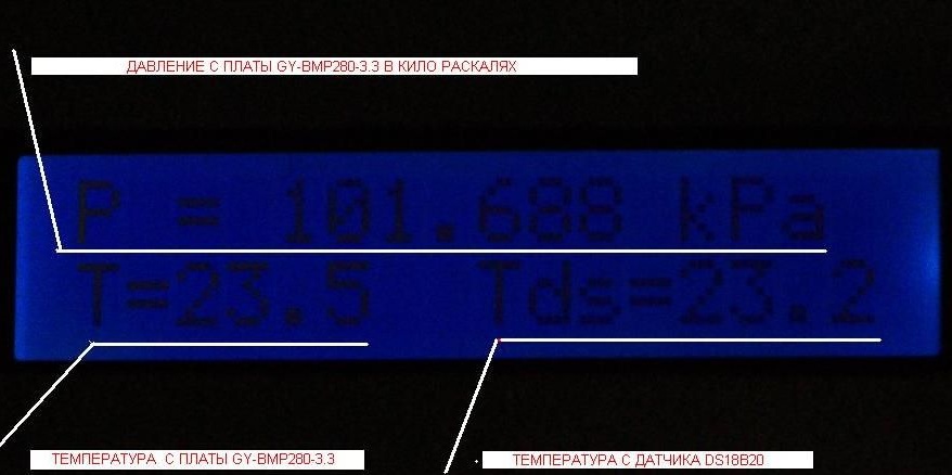
The GY-BMP280-3.3 board gives out pressure in pascals, which is not very convenient. I could not solve the problem of how to make the GY-BMP280-3.3 board output pressure data in kilopascals. I solved this problem in the output line of the LDC display.
lcd.print (sensor.pressure / 1000.3); // divide the value of P issued by BMP280 by 1000 and set the output of 3 decimal places
The GY-BMP280-3.3 board also provides altitude values.
sensor.begin (73); // Initiate work with the sensor. The current altitude will be taken as 73 m. - the height of the city of Buzuluk above sea level
If you will relax at sea and change “sensor.begin (73);” on "sensor.begin (0);" in the code, and then compile and save the program to the home weather station on the GY-BMP280-3.3 and Ds18b20, and make a height output to the LDC display, you will also get an altimeter.
// lcd.setCursor (9,1);
// lcd.print ("H =");
// lcd.print (sensor.altitude, 1); // Print the height values in meters with one decimal place
The power is supplied to the circuit in my version via a USB cable. You can use a 5V / 600 mA low-voltage boost pulse converter and your weather station will become portable. This type of power supply is well described in article.
Successful compilation!