1. The engine from the refrigerator is the compressor itself!
2. The receiver is a tank that holds pressure.
3. Pressure switch - turns the engine on and off.
4. Pressure gauge - it can be used to determine the pressure in the receiver.
5. Pressure reduction gearbox - so that the airflow is uniform and can be adjusted.
6. Dehumidifier. Separates condensate as the air cools during compression. And water when working for example with an airbrush can cause a lot of trouble.
7. Filter gasoline (automobile)
8. All sorts of tees, couplings, adapters, etc. etc. Since the connection to the compressor is not standardized, many options can be used.
9. Well, wires and hoses.
Unfortunately, there are no photos of the phased assembly. But the final result shows what connected and how!
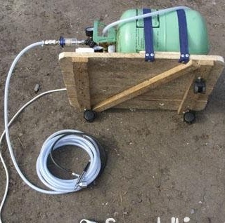
This option is not finished yet, since under it will be welded a frame of 15x15 mm tubes.
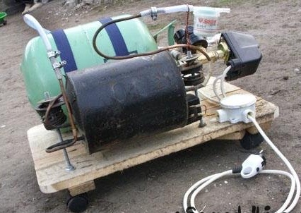
My version of the compressor was made under the airbrush. Its working pressure is about 2 bar. Therefore, I had a tank of reagent for filling the air conditioners on the receiver (its maximum pressure is 3.2 bar).
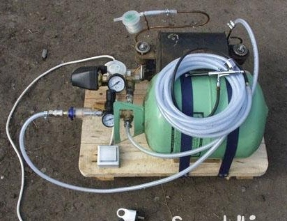
The engine is connected through a switch (so as not to run to the outlet), from a pressure switch. We put a coarse filter (gasoline) on the intake air tube. Connect the air supply pipe to the receiver. The third tube - to replace the engine oil, must remain sealed if there is no plug to close it.
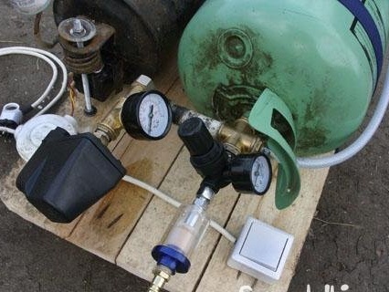
At the outlet of the receiver we put a pressure reduction gear, after it a water separator filter. Everything can be connected airbrush and forward! In my case, learn! In someone else to create!
