» Topics » DIY ideas »Input and output pump control circuit with galvanic isolation

The control circuit of the pump with galvanic isolation at the input and output

Automatic maintenance of the water level in the tank.
Reliable. Automatically maintains the set water level. Collected and used in the country. Used purchased water level sensors.

Description of work.

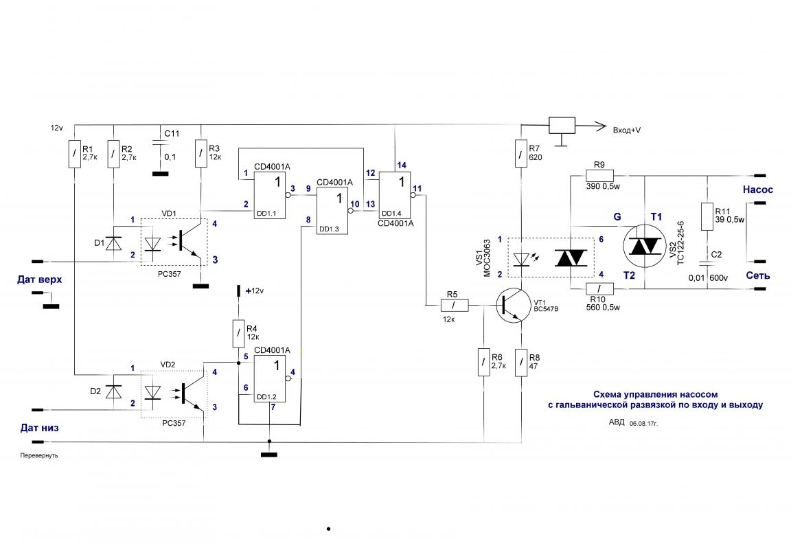
If the water level is lower than both sensors, a logical unit will appear on the 11th output of the DD1.4 chip and the VS2 triac will turn on the pump. With a smooth increase in water level, even if the water contacts the lower sensor, there will still be a logical unit. As soon as the water level reaches the upper sensor at the 11th output of the DD1.4 microcircuit, a logical zero appears, the triac VS2 will turn off the pump and water will not enter the tank. When the water level drops, and the upper sensor will not come into contact with water, then there will still be a logic zero on the 11th output of the DD1.4 microcircuit and the pump will not turn on. But if the water level drops below the lower sensor, then on the 11th output of the DD1.4 chip will appear and the pump will turn on. Pump power no more than 2 kW. The triac is mounted on a radiator. The area of ​​the radiator depends on the power of the pump.


Printed circuit boards (power and control)

The power board and triac are mounted on a radiator
Question \ topic is automatically published in the social. site network - stay tuned for answers there:

Suitable for topic

Related topics

Add a comment

    • smilesmilesxaxaokdontknowyahoonea
      bossscratchfoolyesyes-yesaggressivesecret
      sorrydancedance2dance3pardonhelpdrinks
      stopfriendsgoodgoodgoodwhistleswoontongue
      smokeclappingcraydeclarederisivedon-t_mentiondownload
      heatirefullaugh1mdameetingmoskingnegative
      not_ipopcornpunishreadscarescaressearch
      tauntthank_youthisto_clueumnikacuteagree
      badbeeeblack_eyeblum3blushboastboredom
      censoredpleasantrysecret2threatenvictoryyusun_bespectacled
      shokrespektlolprevedwelcomekrutoyya_za
      ya_dobryihelperne_huliganne_othodifludbanclose
3 commentary
Quote: Ivan_Pokhmelev
Quite the contrary, their purpose is not clear: they do not provide galvanic isolation from low-voltage power; the isolation from mains voltage must be in the power source. Moreover, since the sensors are not electrically in contact with water, galvanic isolation from low voltage is not required.

Sorry, I just didn’t put it that way when I assembled a similar circuit, I connected the sensors through a resistor to a divider of two resistors (I selected the input level), the diode directly to the input of the element and no, but the output through 315 to an optocoupler .... Well, then somewhere else the same. There it was necessary to create a low-impedance input to the sensor (a piece of copper wire in isolation with a stripping of 1 cm.in contact with water), taking into account water resistance.
Quote: vektorss
They do not eliminate the "bounce of contacts" ...
Of course, bounce eliminates the RS-trigger DD1.1, DD1.3.
Quote: vektorss
No, their galvanic isolation with common nutrition is understandable.
Quite the contrary, their purpose is not clear: they do not provide galvanic isolation from low-voltage power; the isolation from mains voltage must be in the power source. Moreover, since the sensors are not electrically in contact with water, galvanic isolation from low voltage is not required.
But why do we need optocouplers VD1 and VD2? They don’t eliminate the “bounce of contacts” ... No, their galvanic isolation with common power is clear.

We advise you to read:

Hand it for the smartphone ...