» Electronics » Sound and Acoustics »The simplest sound amplifier on one transistor in 15 minutes

The simplest sound amplifier on one transistor in 15 minutes


To do this, we need the following components and tools:
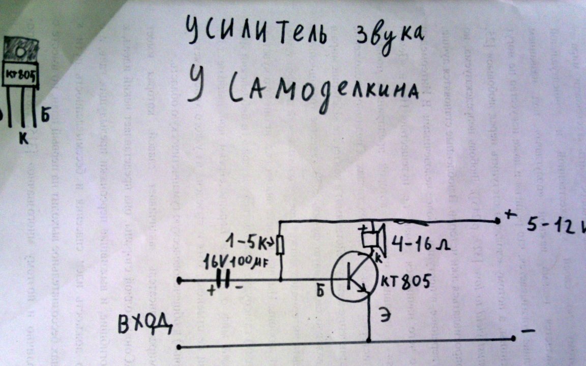
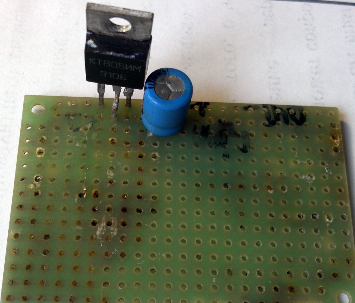
1. n-p-n silicon transistor KT805 or its analogues. (this is the most powerful in the series)
2. Electrolytic capacitor with a capacity of 100 μF and a voltage of more than 16 volts
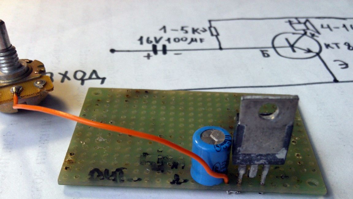
3. Variable resistor about 5kΩ
4. circuit board (optional - can be done by wall mounting)
5. radiator
6. wires
7. mini jack
8. 5-12 V DC power supply
9. soldering iron, rosin, solder.

(such stuff is chosen)

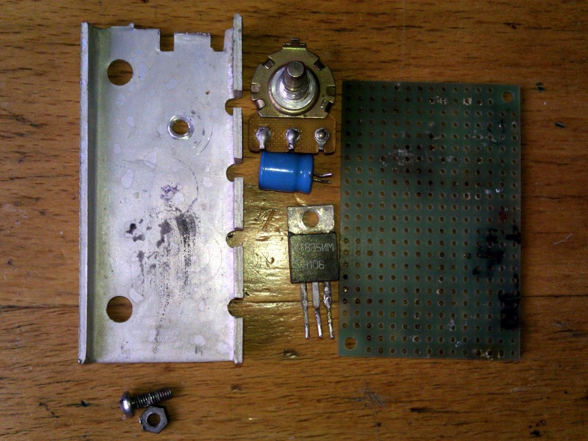
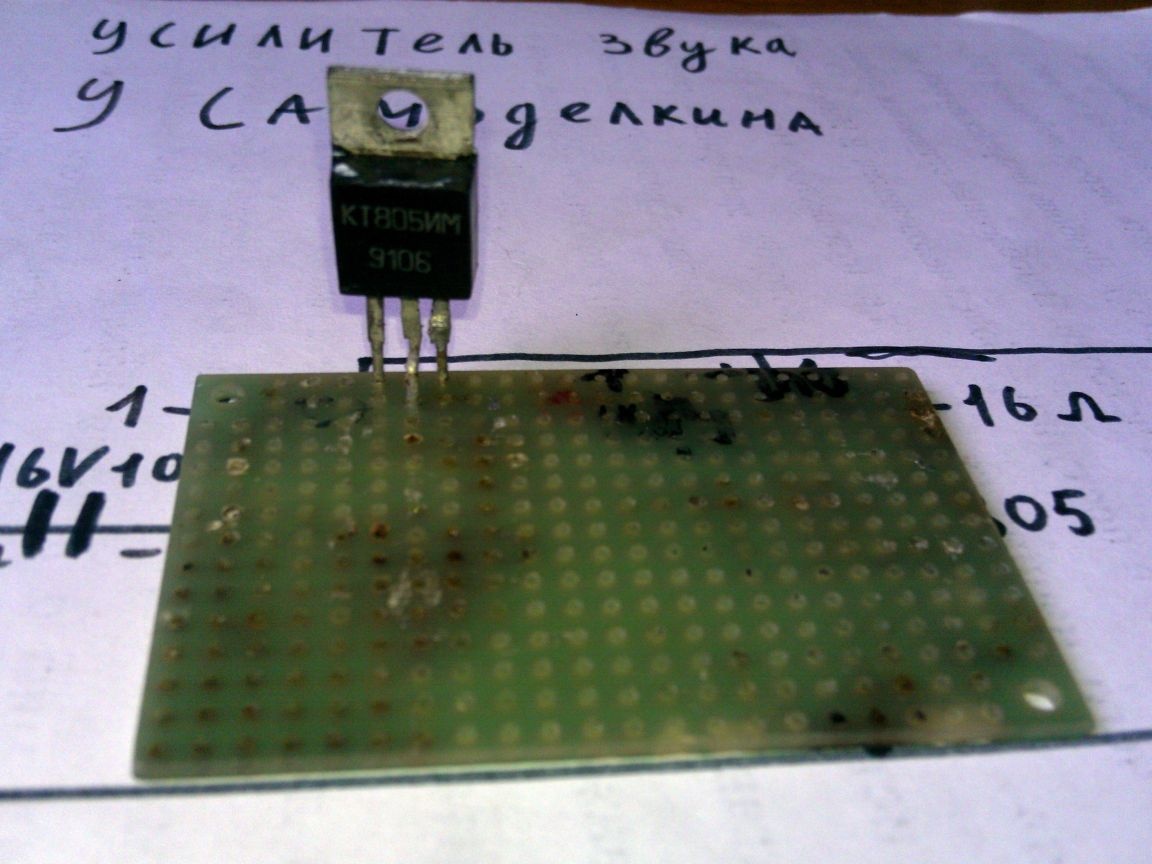
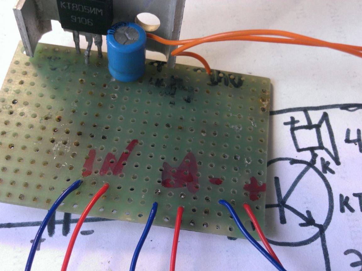
First of all, we install the components on the circuit board.


We solder the central terminal of the variable resistor and the negative terminal of the capacitor to the KT805 base.


The second output of the variable resistor is + power and + dynamics soldered to the board
The transistor collector (center pin) will be minus the speaker.


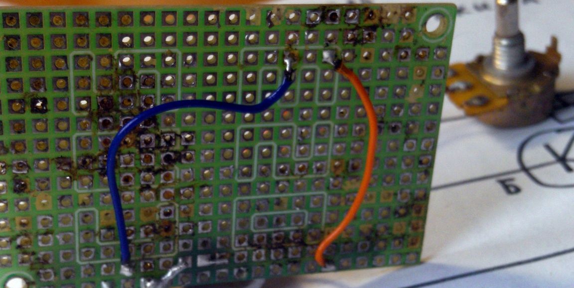
We connect the minus power and the negative wire of the input signal to the emitter. The positive wire is + capacitor.


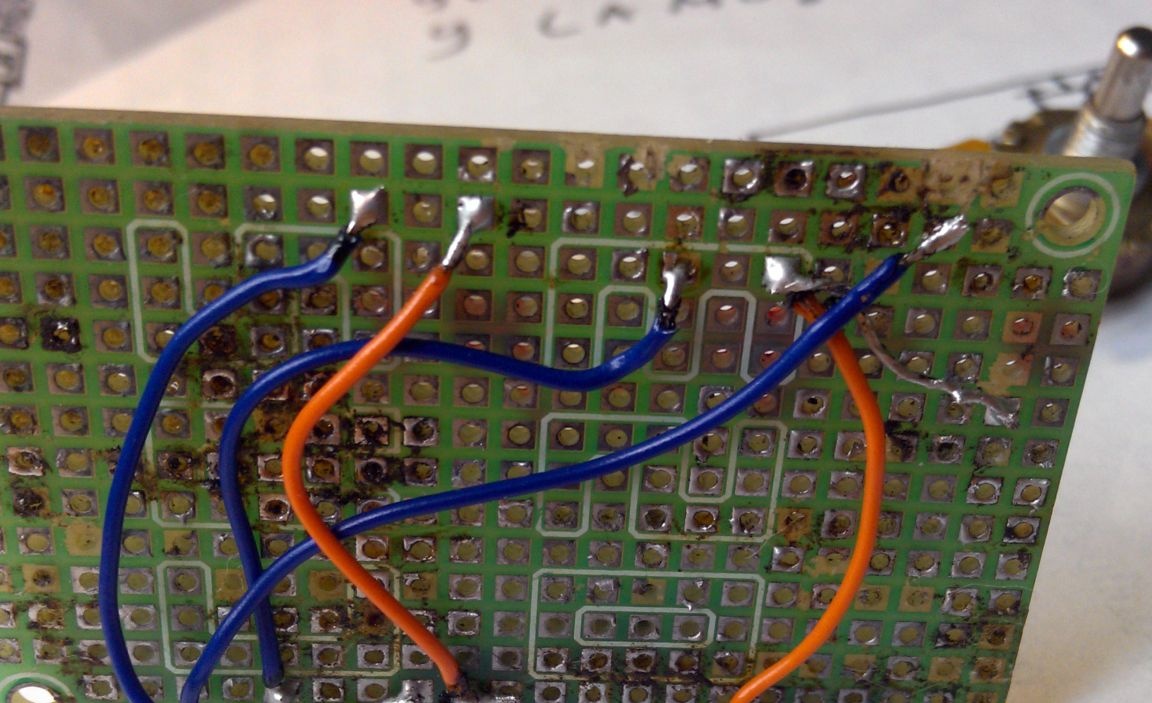
For tests, it remains to solder 3 pairs of wires Input Output and Power (in the photo from left to right). We install the transistor on a radiator.


Getting started with tests and tuning. We assemble and connect all the components on the table, strictly observing the polarity! It is advisable to check the circuit for short circuits.

Our tuning resistor selects the correct mode of operation. In short, we coordinate the operation of the transistor with the resistance of the speaker.


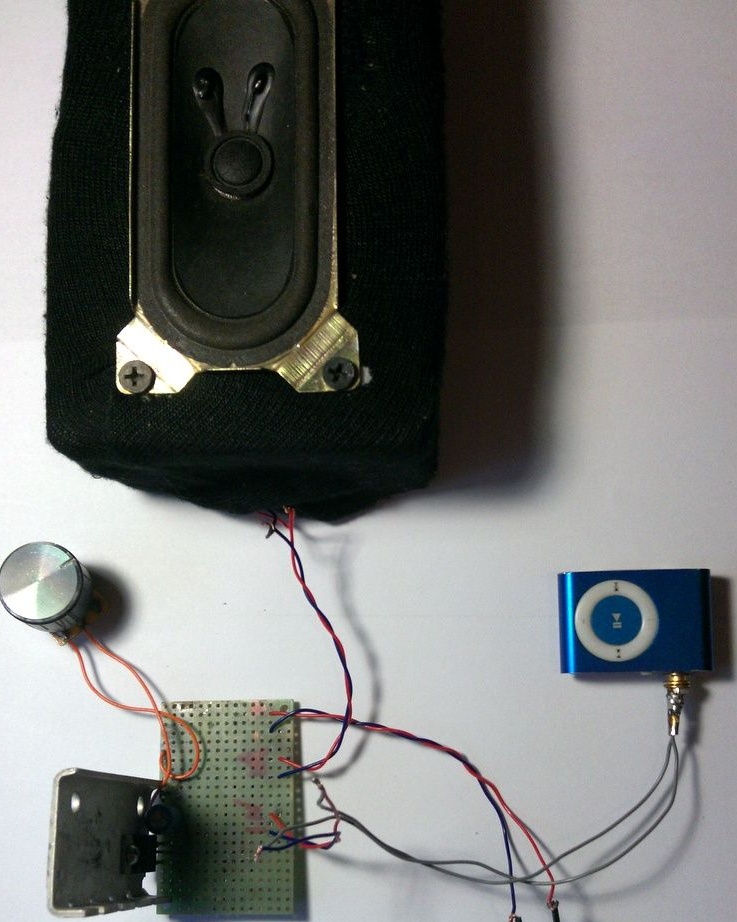
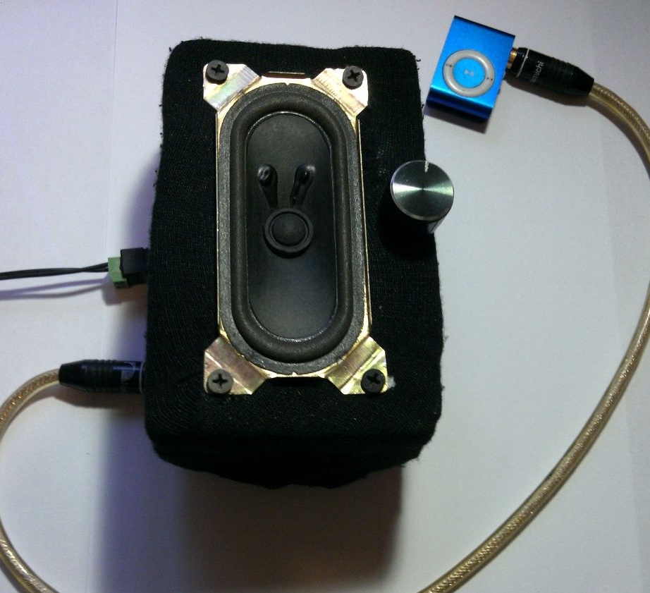
Hurrah! Setup was successful! We cultivate and install everything in the housing.


8.1
7.1
6.7

Add a comment

    • smilesmilesxaxaokdontknowyahoonea
      bossscratchfoolyesyes-yesaggressivesecret
      sorrydancedance2dance3pardonhelpdrinks
      stopfriendsgoodgoodgoodwhistleswoontongue
      smokeclappingcraydeclarederisivedon-t_mentiondownload
      heatirefullaugh1mdameetingmoskingnegative
      not_ipopcornpunishreadscarescaressearch
      tauntthank_youthisto_clueumnikacuteagree
      badbeeeblack_eyeblum3blushboastboredom
      censoredpleasantrysecret2threatenvictoryyusun_bespectacled
      shokrespektlolprevedwelcomekrutoyya_za
      ya_dobryihelperne_huliganne_othodifludbanclose
11 comments
There is no stabilization of the operating point of the transistor.When heated, it will float away. The quiescent current of the transistor will flow through the speaker coil, causing magnetization. No limiting resistor is provided in the bias circuit. This will lead to the fact that when tuning, at the extreme or close to the extreme position of the trimmer resistor engine, when the base of the transistor is directly connected to the power plus, the emitter junction of the transistor will burn out almost instantly. And the speaker too. xaxa And so, it is still desirable to correctly turn on the input electrolytic capacitor, that is, a plus to the base of the transistor.
Guest Pavel
I would add that to turn on such a low-impedance load as a speaker, it would be better to use a circuit with a common collector, and to connect the speaker to the emitter circuit.
Readers! Remember the nickname of this author and never repeat his scheme.
Moderators! Before you ban me for insulting, think that you "let the usual gopnik get to the microphone," which you can’t even get close to radio engineering and, especially, to beginner training.

Firstly, with this switching scheme, a large direct current will go through the transistor and speaker, even if the variable resistor is in the right position, that is, music will be heard. And with a large current, the speaker is damaged, that is, sooner or later, it will burn out.

Secondly, in this circuit, there must be a current limiter, that is, a constant resistor, at least 1 KOhm, connected in series with the variable. Anyone will turn the regulator of the variable resistor to the stop, it will have zero resistance and a large current will go to the base of the transistor. As a result, the transistor or speaker will burn.

A variable input capacitor is needed to protect the sound source (the author should explain this, because immediately there was a reader who removed it just like that, considering himself smarter than the author). Without it, only those players in which the output already has a similar protection will work normally. And if it is not there, then the output of the player may be damaged, especially, as I said above, if you unscrew the variable resistor "to zero". At the same time, the voltage from the power source of this penny trinket will apply to the output of an expensive laptop and it can burn out. the inhabitants of our site are very fond of removing protective resistors and capacitors, because "it works the same!" As a result, a circuit can work with one sound source, but not with another, and even an expensive phone or laptop can be damaged.

The variable resistor in this circuit should only be trimmer, that is, it can be adjusted once and closed in the case, and not be brought out with a convenient handle. This is not a volume control, but a distortion control, that is, it selects the operation mode of the transistor so that there is minimal distortion and that smoke does not come out of the speaker. Therefore, it should in no case be accessible from the outside. Adjust the volume by changing the mode NOT. For this you need to "kill." If you really want to adjust the volume, it’s easier to turn on another variable resistor in series with the capacitor and now it can already be output to the amplifier housing.

In general, for the simplest circuits - and to work right away and not to damage anything, you need to buy a chip like TDA (for example, TDA7052, TDA7056 ... there are many examples on the Internet), and the author took a random transistor that was lying around in his desk. As a result, gullible amateurs will look for just such a transistor, although it has only a gain of 15 and an allowable current of as much as 8 amperes (any speaker will burn without even noticing).
Everything works. The resistor can be set to the usual kilo (determined experimentally). Please explain one thing. Why is there a capacitor in the circuit? I used the circuit with a capacitor first, but then, in order to reduce the circuit, the conders were removed. I checked on one of the laptops - it works.Normas. And left it. But then he discovered that he was silent on another laptop and on the phone. Author, please tell me.
The speaker is a pity.
Quote: vektorss
Cool scheme !!! And I, the fool, collected on 9 transistors, where the KT805 penultimate cascade ..... It's a shame!

I lived with Tsiolkovsky in the same village. He made a rocket from a barrel - he is still flying into space.
Cool scheme !!! And I, the fool, collected on 9 transistors, where the KT805 penultimate cascade ..... It's a shame!
Well, if only from the wildest hopelessness at once.
The electrolyte has a polarity mess.
Quote: Nruter
Here is the "" please explain.

This is encryption, in case the scheme is stolen
Hi .. This can be safely sold to China ..
Here is the "" please explain.

We advise you to read:

Hand it for the smartphone ...