

Good day, the inhabitants of our site!
We decided today to get confused with the following question - there is an ancient radio tape recorder in the kitchen. Due to the fact that in the room on the computer almost round the clock plays online radio (chillout or jazz with classics) I wanted to duplicate the same music in the kitchen. Laying the wire - according to a relatively recent repair, and using heavy equipment in the form of a punch was somehow quite a bummer.
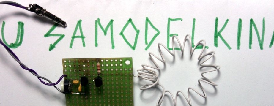
So the idea was born to make an FM transmitter and give a signal through it to a radio in the kitchen.
Yes, it will be mono. With the size of the radio - stereo is not heard there =)
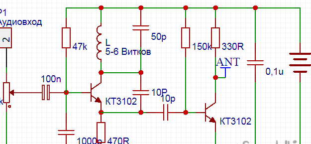
This time, the craft will already be from new components. Troubles began immediately. I killed half a day to sort the stocks of resistors and capacitors, it turned out that half of the required denominations in the SMD, half were ordinary legged. Have to make a hodgepodge. A wire for the 0.3mm coil was found immediately. Of the transistors - too, at first I thought to install the SMD BC847 - in the end I settled on the Soviet classic KT3102.
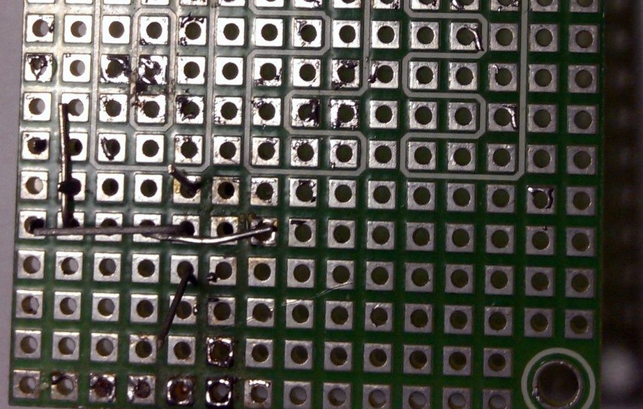
If you use one like mine - don’t cut off the legs on the parts right away - they make plus and minus tires, as well as something like tracks.
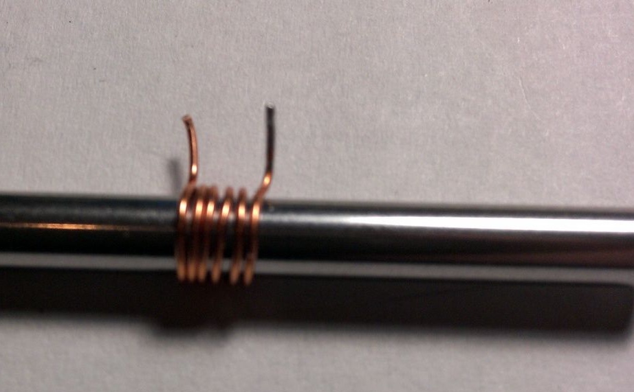
Regarding the determination of the diameter of the wire with a standard ruler, without a micrometer and caliper. We act in the same way as in the task - to determine the weight of the coin if the error of the weights is higher than its weight. Namely - we wind a couple of dozen turns tightly in one row on the rod - and measure with a ruler. The winding width is divided by the number of turns and we get the diameter of the wire.
Materials and components
1. Wire 0.3-0.5mm - ten cm
2. or analogues - 2pcs
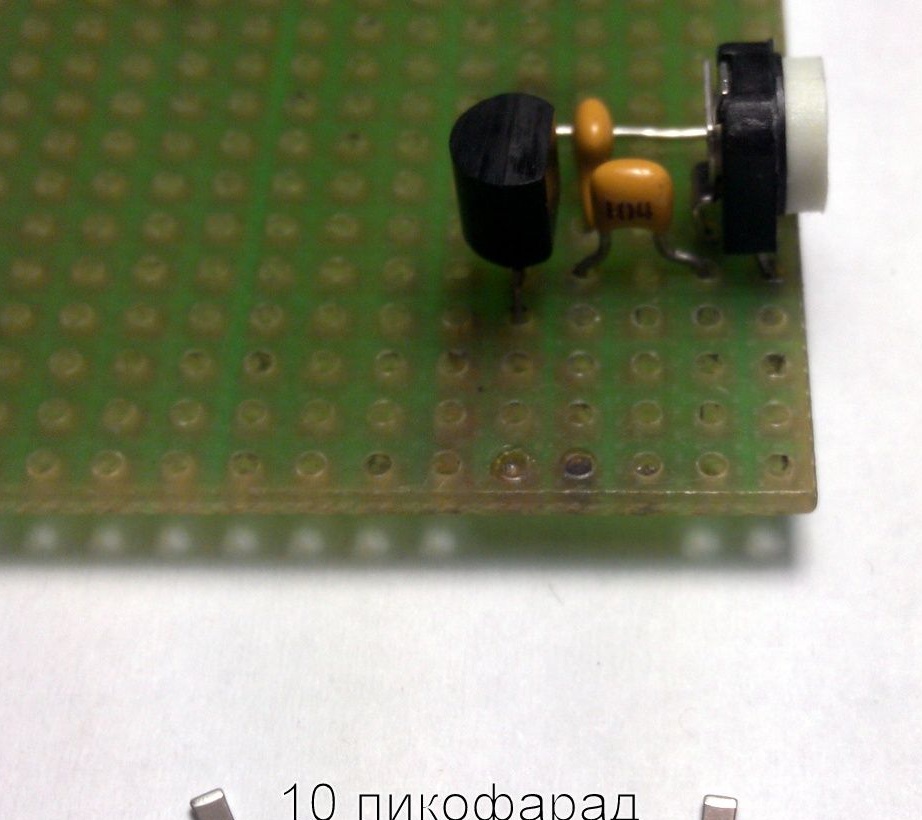
3.10pF - 2pcs
4.100nF - 1pc
5.1000pF -1pcs
6. 0.1mF -1pcs
7. 50pF - 1pc
8.- from 10K to 100K
9.47 kOhm -1pcs
10.470 Ohms - 1 pc.
11.150 KOhm - 1 pc.
12.330 Ohm -1pcs
Battery - battery - power supply - a choice of 3 to ... 12+ volts (depending on the transistor). I put the battery from the phone 3.7V. With increased voltage today did not play. I'll leave it next time, we will reduce the size. Weed a shawl and weird everything on SMD.
So, drove to solder!
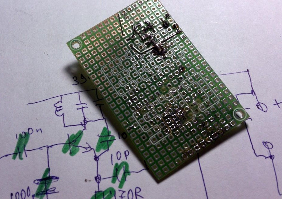
I did not plan the arrangement of elements in advance, so I will do the positioning during the course of the play.
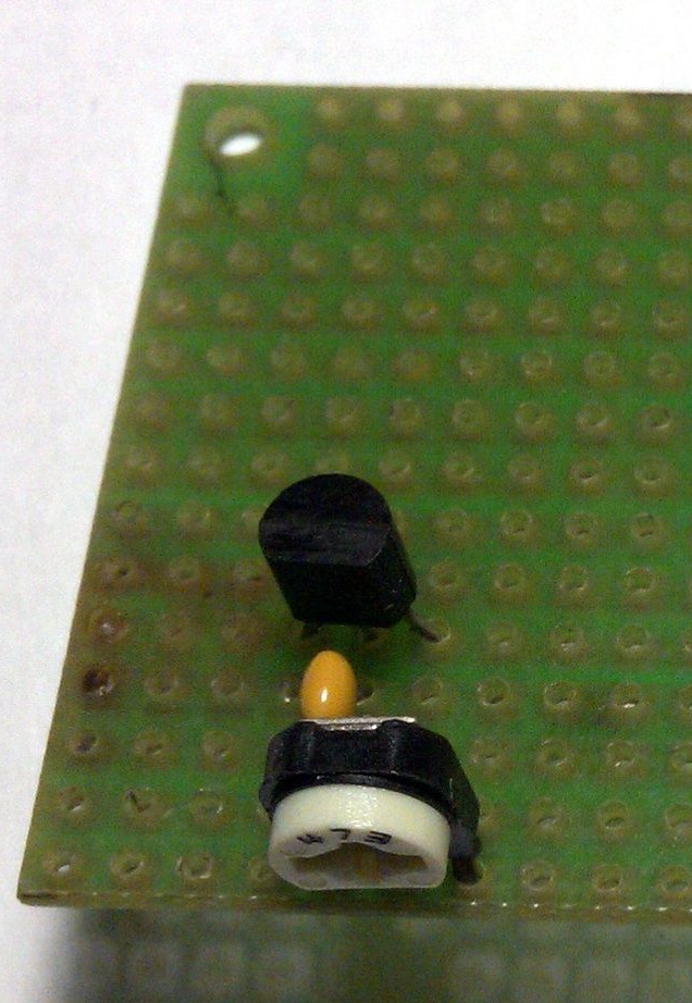
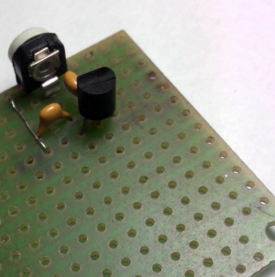
I dialed the first three elements - a trimmer, a transistor and an input capacitor.
His legs are bent so far.
He bit the superfluous and soldered the tuning resistor, transistor base and capacitor.
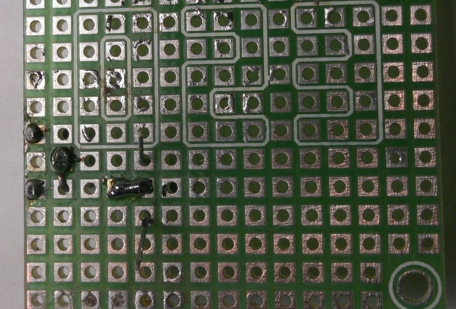
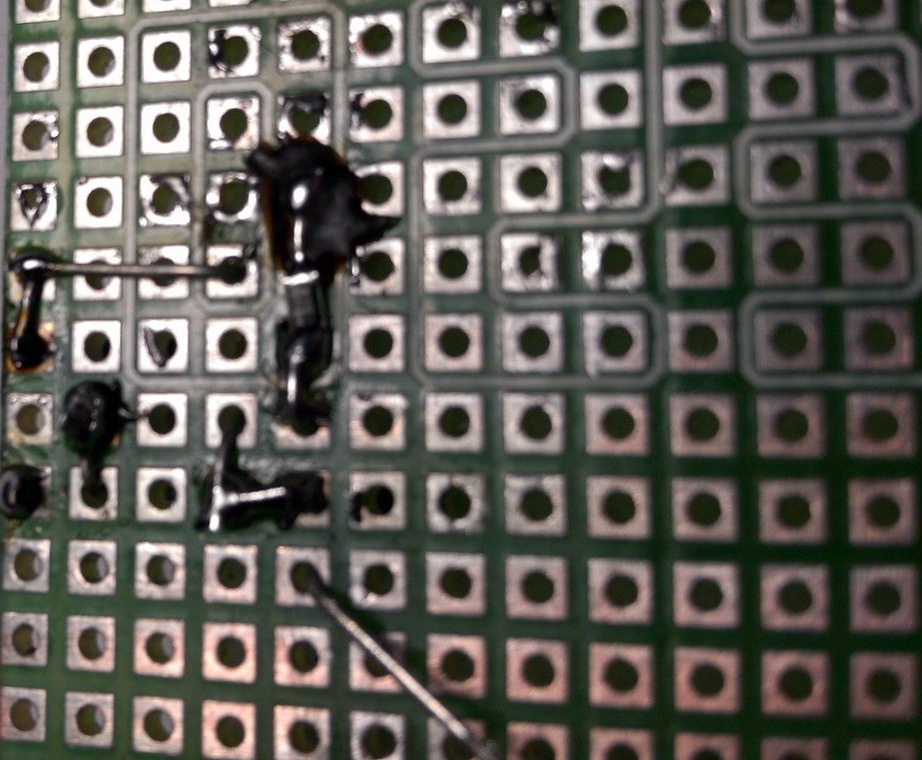
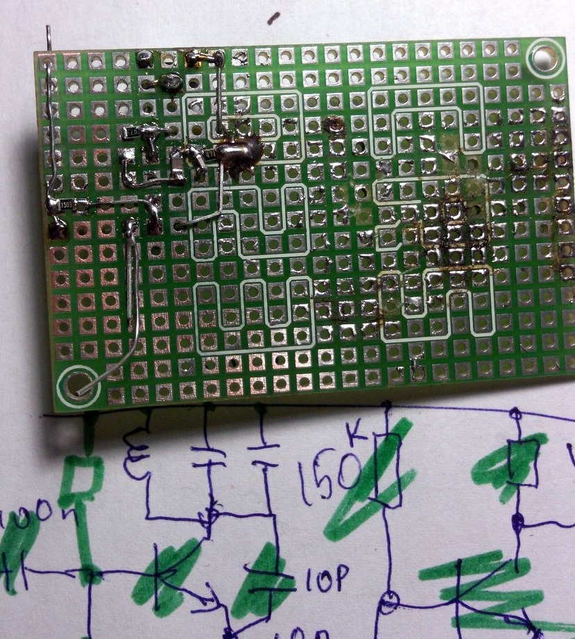
I collect further. left - threw a negative jumper, put another capacitor.
We drove with SMD to indulge =)

Then it became clear to me that the scheme would come out well, just microscopic. Yes. in green on the diagram I cross out what I already installed. Otherwise, then think about what you forgot or what you set. Especially smaller SMDs, and it’s good if all capacitors have the same rating. Capacitors are not marked in any way - go and then guess what soldered.
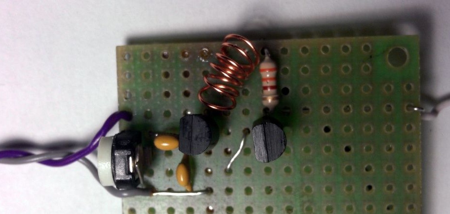
It's time to wind the coil.
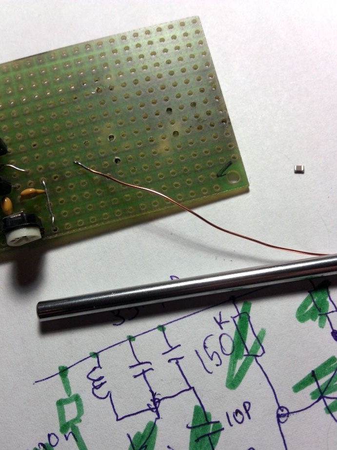
I wind on a 4mm diameter rod, 0.3 wire. Varnish before winding removed on one side and tinned.
I cleaned the second end with a sharp knife after winding. We tin it too.
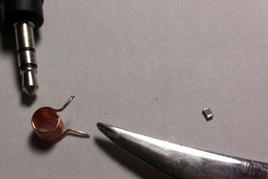
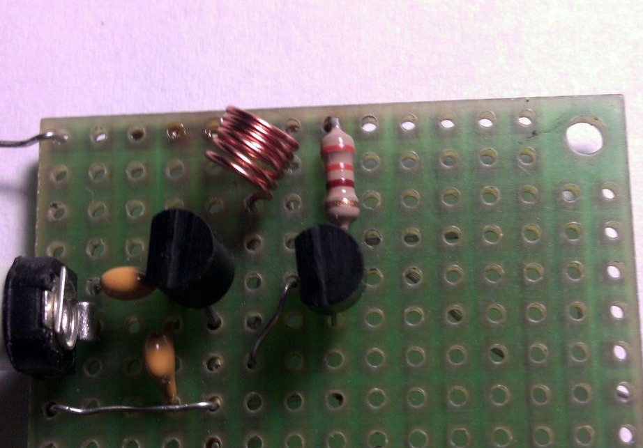
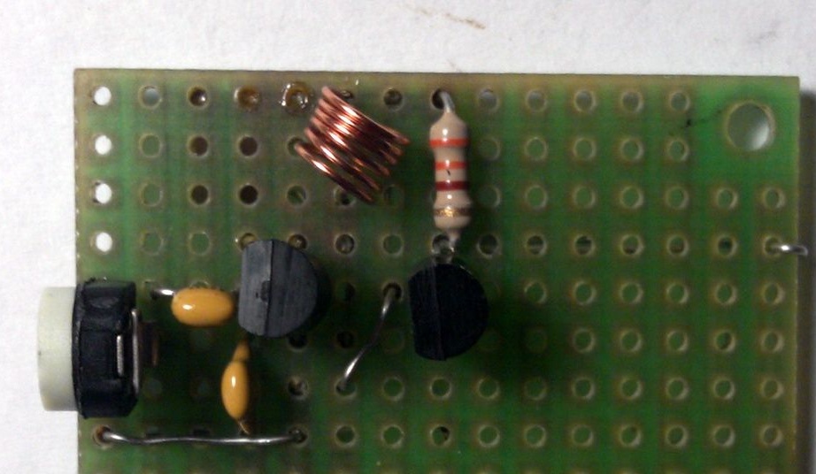
I found a convenient place for the coil, and soldered it.
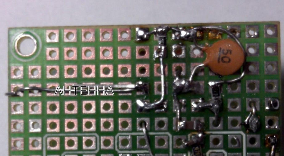
I solder 50 picofarads on the back side in case it does not fit and you have to choose from smaller ones. Right in the photo I signed the antenna output.
Soldered the antenna and input wires, battery.
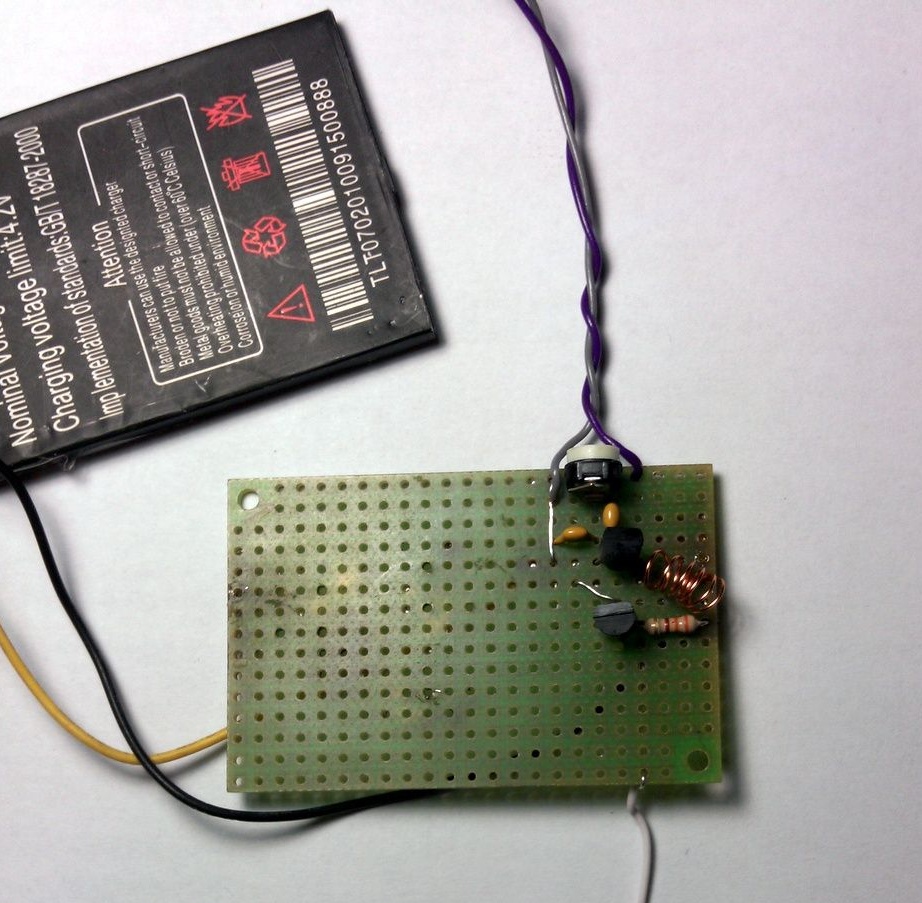
So now the launch!
Earned the first time. Hit the bottom of the FM band. I played with the coil, parted the coils for it and tuned in to a frequency free from radio stations of 87 MHz. It covered all the rooms and the kitchen. We decided with my son to check the range - 50 meters on the street beats. To increase the radius of the coating, you can increase the voltage or put a more powerful output transistor, but there was no such purpose. And why should my neighbors listen to my music. Since I have a private sector, when broadcasting from home, coverage of almost only my small area is small. No longer takes from a neighbor in the house! Perfectly turned out.
What is a trimmer for? We will adjust the volume level of the input signal with it, because I gave it a signal from Audigy PRO - and there - all good 500mV. Simply put, remove distortion and limit the input signal.
How to apply an audio signal ... From ANY sound source where headphones or a tulip-type connector are inserted. Up to 500mV.
According to consumption. Very economical shemka. Only 15mA of current with a 3.7 volt Li-Ion battery from the phone. That is, a 1500 mA battery is enough for 100 hours or 4 days of continuous operation.
Most likely, we will now equip a portable audio speaker with such a transmitter. Or, in general, solder the USB connector to it in the form of a power source and a charger ... let it work for a couple of days as a home radio station.
We were very pleased with the simplicity of the schematic, and I did not solder something quite a while ago.
Good luck to everyone and good ideas!