» Electronics » Power supplies »Simple 1-30V laboratory power supply

Simple laboratory power supply 1-30V

A radio amateur, and especially a master, cannot do without LBP. Only here the prices bite. I propose my own version of a budgetary and easy to repeat laboratory technician:

For this we need:

Instruments :
dremel (or anything for making holes)
files, files,
screwdrivers
wire cutters
soldering iron

Details

transformer
microcircuit LM 317
diodes 1N4007 - 2 pieces
electrolytic capacitors:
4700 uf 50v
10uf 50v
1uf 50v
constant resistor 100-120 Ohm x 3-5 W
2.7 kOhm variable resistor (better wire, but any will do)
voltmeter
ammeter
phone and car charger
terminals
switch

ASSEMBLY

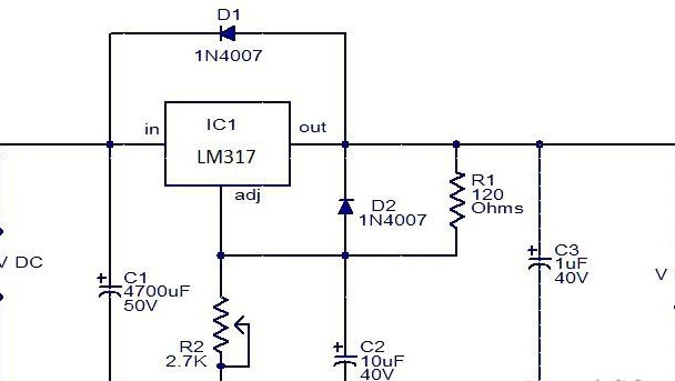
First, let's decide on the regulator circuit. On the Internet, their carriage and a small cart, choose the taste.
I probably chose the simplest and easiest to repeat, and yet it is the same workable.

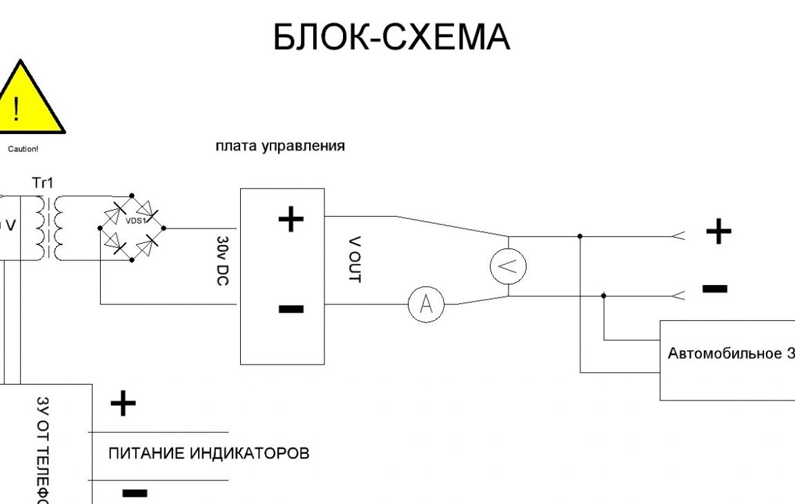
For clarity, I sketched a block diagram of my device, but it is not necessary to repeat exactly, the scope for imagination is unlimited.

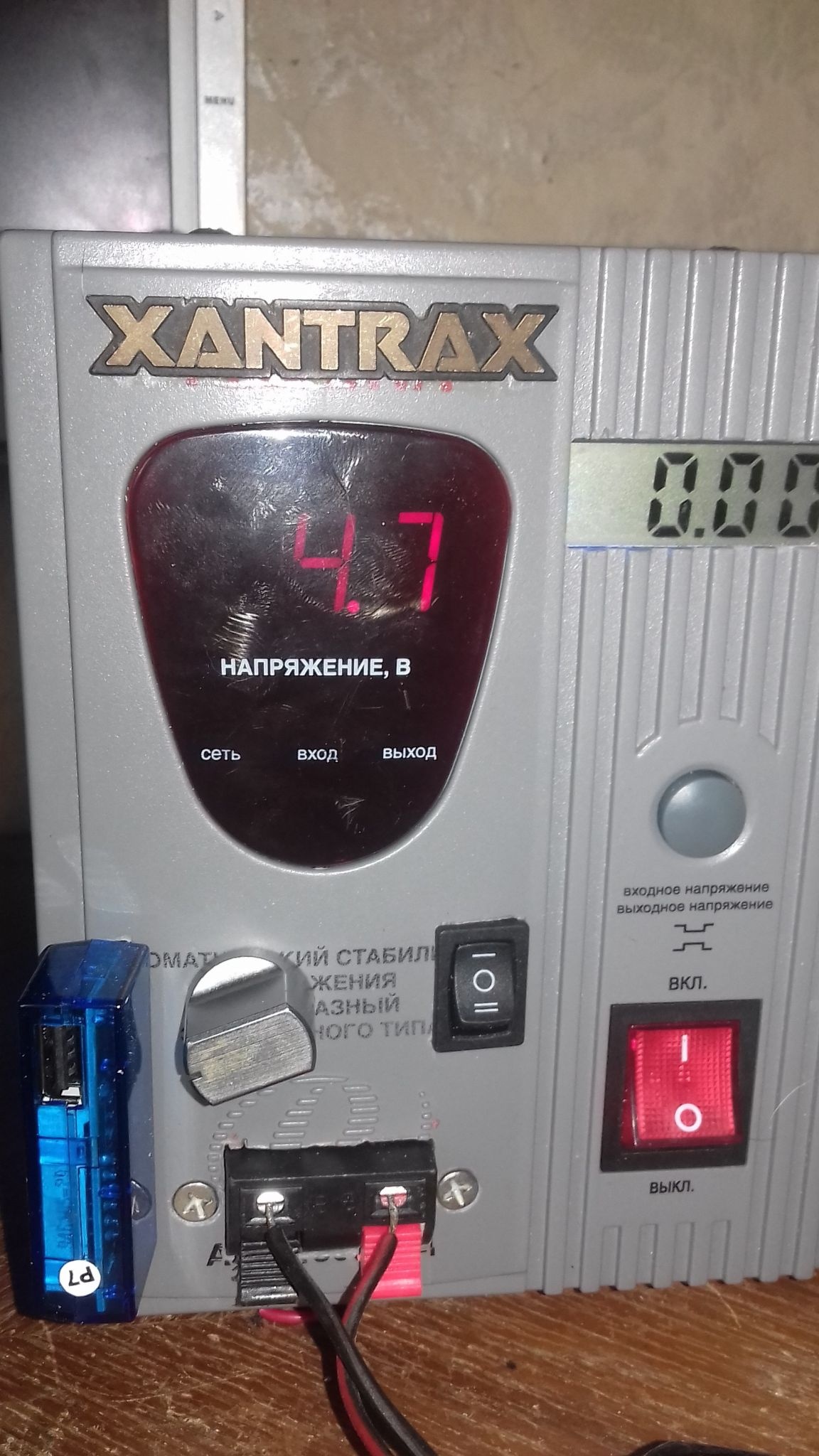
Next, we decide on the body. They gave me a very useful dead voltage regulator.
Simple laboratory power supply 1-30V

We remove the insides and begin to fill with new ones (I hope everything is already soldered and laid out on the table)


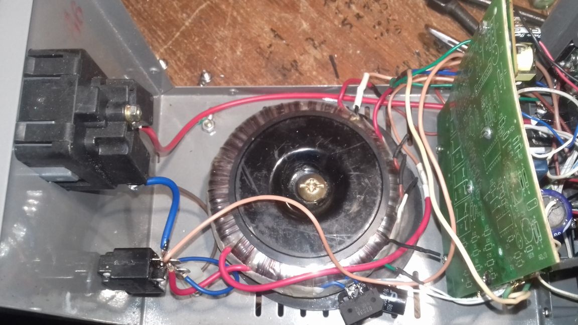
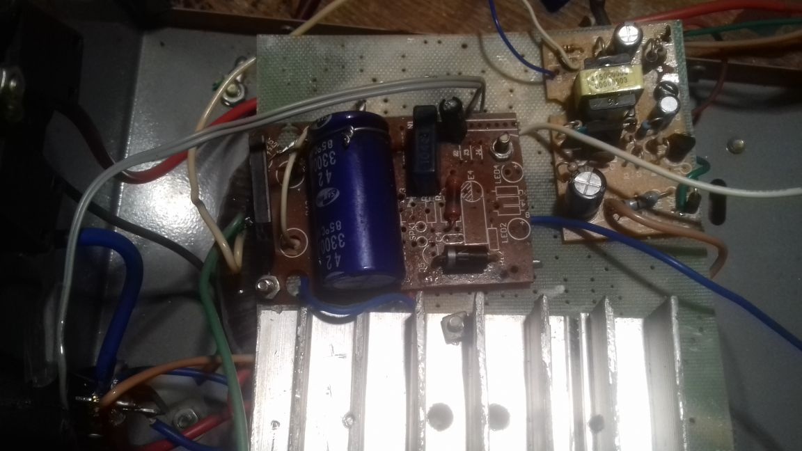
Transformer. The main and most expensive part, but if there is no suitable one in the zashniks, then I do not advise saving. A toroid with an output voltage of 12 - 30 V and a current is best suited ... Well, a lot does not happen, but not less than 3 A.

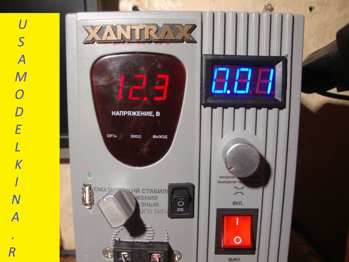
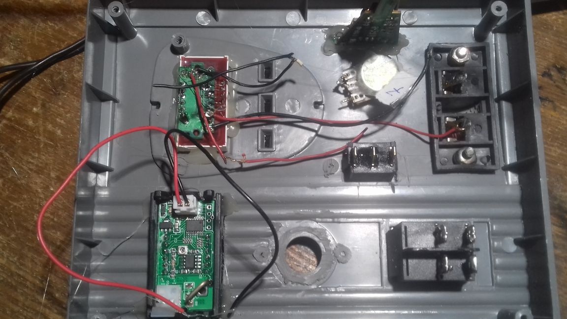
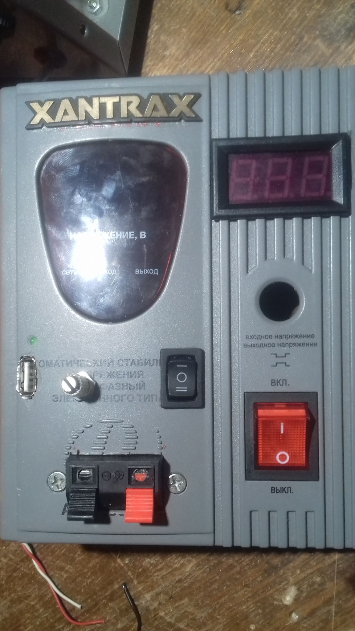
In the front part, cut out the necessary holes. My voltmeter went to a regular place, and the same mains switch remained in place. I was a little wiser with an ammeter, initially I used an unnecessary DT-830 multimeter, setting it to 10 A, then I got hold of a normal LED. Here are both options, as you like more:


I used a charger from the phone to power the indicators, any one is suitable, but another solution is possible: if your transformer has not one but several secondary windings, then select the desired voltage (usually from 4 to 12 V) and power it through the diode bridge. In the version with a multimeter, remove the zener diode from the charge. Next, we need car charging for ... Well, for charging phones))) Why car? Because it will be connected in parallel with the output terminals of the PSU, and since it has its own stabilizer, which easily withstands 30 V, accidentally turning the regulator you will not burn the gadget.Of course, it’s possible to solve it easier and solder the USB connector to the network charge, which feeds the measuring heads, but in this case the current consumption of the connected device will not be reflected on the ammeter. In my case there was a nice bonus in the form of an outlet, we also use it. For example, to connect a soldering station or a lamp.

Well, in general, our LBP is ready. Good luck to all !

Implement video:
7.5
7.5
7.5

Add a comment

    • smilesmilesxaxaokdontknowyahoonea
      bossscratchfoolyesyes-yesaggressivesecret
      sorrydancedance2dance3pardonhelpdrinks
      stopfriendsgoodgoodgoodwhistleswoontongue
      smokeclappingcraydeclarederisivedon-t_mentiondownload
      heatirefullaugh1mdameetingmoskingnegative
      not_ipopcornpunishreadscarescaressearch
      tauntthank_youthisto_clueumnikacuteagree
      badbeeeblack_eyeblum3blushboastboredom
      censoredpleasantrysecret2threatenvictoryyusun_bespectacled
      shokrespektlolprevedwelcomekrutoyya_za
      ya_dobryihelperne_huliganne_othodifludbanclose
9 comments
Quote: infrazvuk
will assemble a powerhouse with protection against short circuit
Protection against short circuit and in your unit is.
Quote: infrazvuk
Have you turned the current regulator on your sophisticated PSU for a long time? Most likely, as initially set to the maximum, they forgot.
You do not judge by yourself. If you don’t know what you can do and need use the current generator mode, this does not mean that your voltage source can be called "laboratory".
Quote: infrazvuk
Powerful resistor in order to charge helium batteries.
Well if "helium", then it is clear!)) Explain how your desire to charge is connected helium R1 batteries?
Quote: infrazvuk
What did you dislike about the location of the indicators? At the factory, exactly the same)))

Not exactly the same! The location of the indicators at different heights looks bad.
Quote: infrazvuk
It is easy to criticize everyone from right to left, having behind them ... 0 (zero) homemade products.
Not an argument at all!
Author
I answer immediately to everyone: Ivan Pohmelev : Have you turned the current regulator on your sophisticated PSU for a long time? Most likely, as initially set to the maximum, they forgot.
A powerful resistor in order to charge helium batteries. Regarding auto-charging, yes, you’re right, the stub will measure it, but after a quick glance, you can display the actual current consumption of the device. Next: I wonder why you did not like the location of the indicators? At the factory, exactly the same))) Well, a little on my own: It is easy to criticize everyone from right to left, having behind them ... 0 (zero) homemade products.
MNS1961 : and yur.pickalov Actually, you are right, this is not a lab specialist in the understanding of a professional, but this homemade product is designed for beginners, and it is quite functional. Do you remember yourself? When you put together a squeaker on two mp-42s, how much joy was there? So the one who will come in handy as the first steps will be interested in my “creation” and in a couple of months will assemble a powerhouse with protection against short-circuit, with the adjustment of all possible parameters, with a coffee maker and the orienter of the universe in the form of additional options. Good luck
soon the detector receiver will be issued as a super, all-waved RPK. And this LBP for beginner hams and that does not pull
At first glance, the homemade product is fire, titanic. The characteristics of the device are more modest. Description - hard for perception, this is my personal point of view. But generally well done!
Quote: MNS1961
Here is a cool case.

But even it could not be used correctly: the location of the controls and displays on the front panel is very unsuccessful.
Quote: Ivan_Pokhmelev
This is not quite the right laboratory source: there is no adjustment of the output current.

I agree 100%. I’ll even add that this device can’t be called a LAB power source, because its maximum current is only 1.5A and the stabilization of the LM 317 leaves much to be desired.
Here is a cool case.
The result was a "brick in a gold frame."
Quote: Ivan_Pokhmelev
not this current will be displayed, but the input current of the stabilizer.

But if your car charger is a two-pole current generator, which I really doubt, then the charge current will be displayed correctly.
This is not quite the right laboratory source: there is no adjustment of the output current.
constant resistor 100-120 Ohm x 3-5 W
Why such an amazing power ?!
In this case, the current consumption of the connected device will not be reflected on the ammeter.
And you will already display not this current, but the input current of the stabilizer.

We advise you to read:

Hand it for the smartphone ...