
The relay is used for switching AC circuits ..., AC loads such as lighting lamps, various fans for working in automatic mode to reduce light, increase temperature, etc.
We also encounter situations when we need to control equipment remotely using a smartphone or we have a sensor that detects the presence of a person and turns on the light, turns the fan on and off. To control these devices, we use a relay board. Let's make a relay board that can be used along with logic circuits or micro-controllers to handle an AC load or high voltage DC load.
Required Details
1. Relay 5/6 in
2.2 resistors 1K
3. 1 1N4007 diode
4. 1 BC548 transistor or similar
5.1.3 pin screw connector
6.1 MCT2E / 817 / 4N35 Optocoupler
Theory and Test Layout
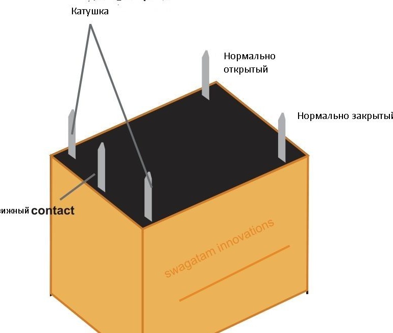
A relay is an electromagnetic switch. Initially, when there is no input signal, com (common) and NC (normally closed) are connected. When the voltage is applied to the input coil, a magnetic field is created and becomes an electromagnet. This magnetic field attracts to com-connects and a contact forms between com and But (normally open).
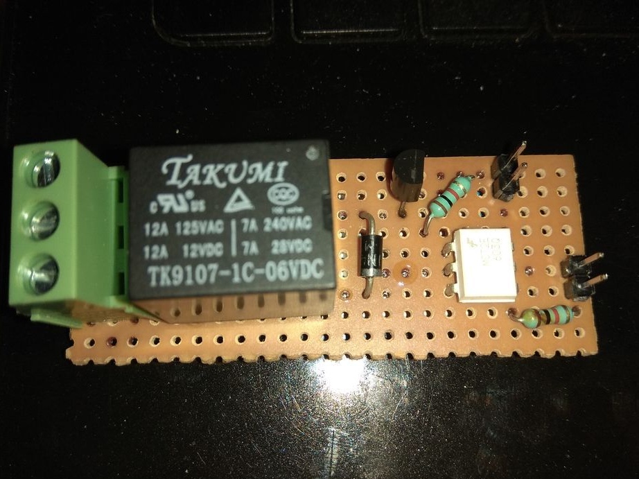
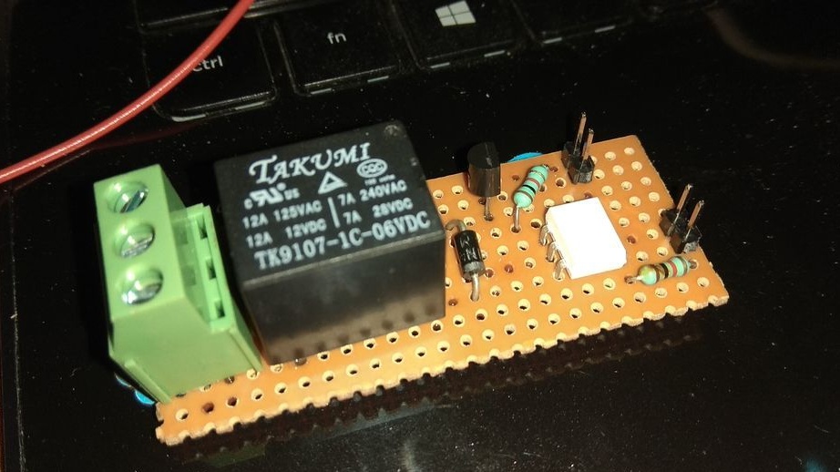
Relay circuit board
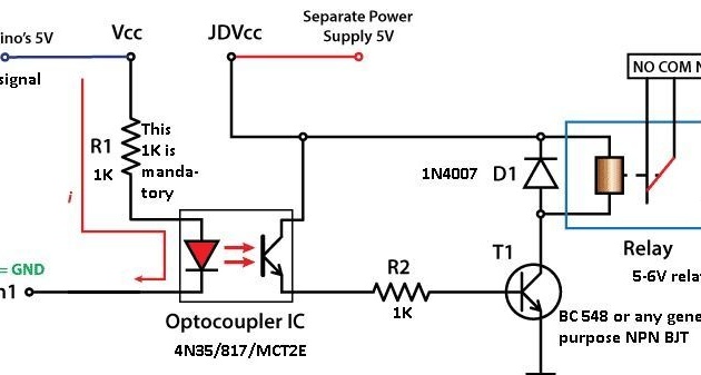
The optocoupler circuit is just an optical isolator ... it has an IR LED at one end and a phototransistor at the other end. When the IR LED lights up and the light hits the base of the phototransistor, the transistor turns on.
The signal from the microcontroller or logic circuit is fed to the IR LED .. and turns it on.
The emitter of the Phototransistor feeds the NPN transistor to the T1 base of BC548 through a 1K resistor, therefore the Darlington configuration is obtained, now B1 * B2 + B1 + B2 (B1 is the current gain of the phototransistor and B2 is the current gain BC548) .... Now that the signal line is high, the IR is on, the phototransistor and BC548 and the current flows through the relay winding and feeds it .. then contact com goes to the contact and, therefore, com and But are closed, .. when the signal line is reduced com and H3 are closed ..
D1 is used as a reverse diode. The circuit works for a while and then turns off, the accumulated induction energy is reset, the voltage can reach 40-60 V, during a very short interval and can damage other components, the diode used provides a circular path for the accumulated energy and dissipates in the diode, keeping the components safe ..
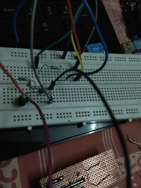
We assemble on the layout and look, with the right connection everything should work ...
Now, after testing the board, we proceed to soldering, look at the circuit and begin to carefully solder. Be careful, because we are dealing with high voltage, so one mistake can ruin everything ... carefully observe the chains with a magnifying glass and light. Test yourself with a tester to find No and NZ, Common.
Now test it under DC load. After successful tests, you can switch to AC loads.
I wish you successful experiments!