
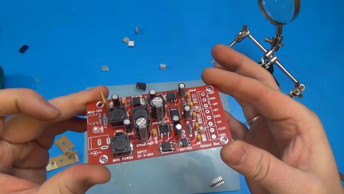
Hello to all lovers of radio designers. In this article, I will tell you how to make a converter of unipolar voltage to bipolar using a kit kit purchased in Ali, by the way, the same sets can be purchased at the radio store in your city, but the price can vary significantly.
This converter will help you power those circuits that require bipolar power, often such power is needed for sound amplifiers.
Before reading the detailed description of the assembly, I suggest watching a video about this kit.
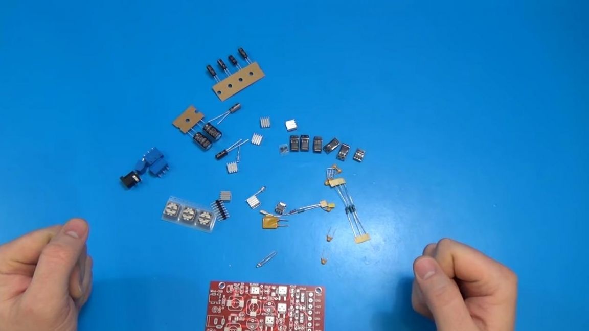
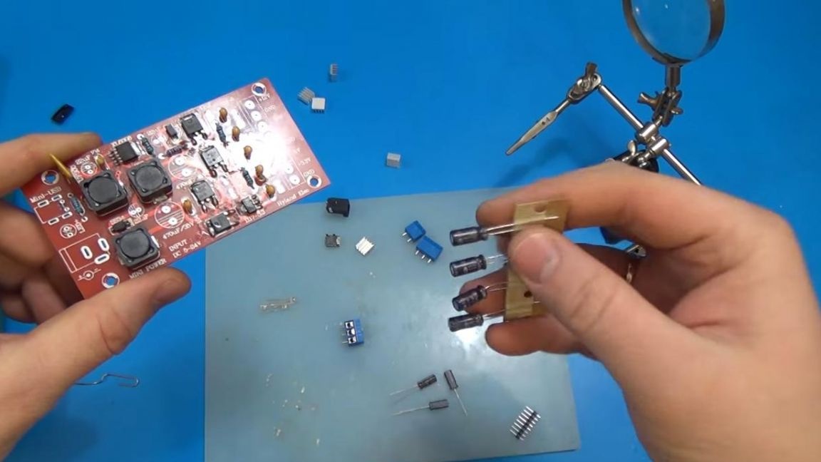
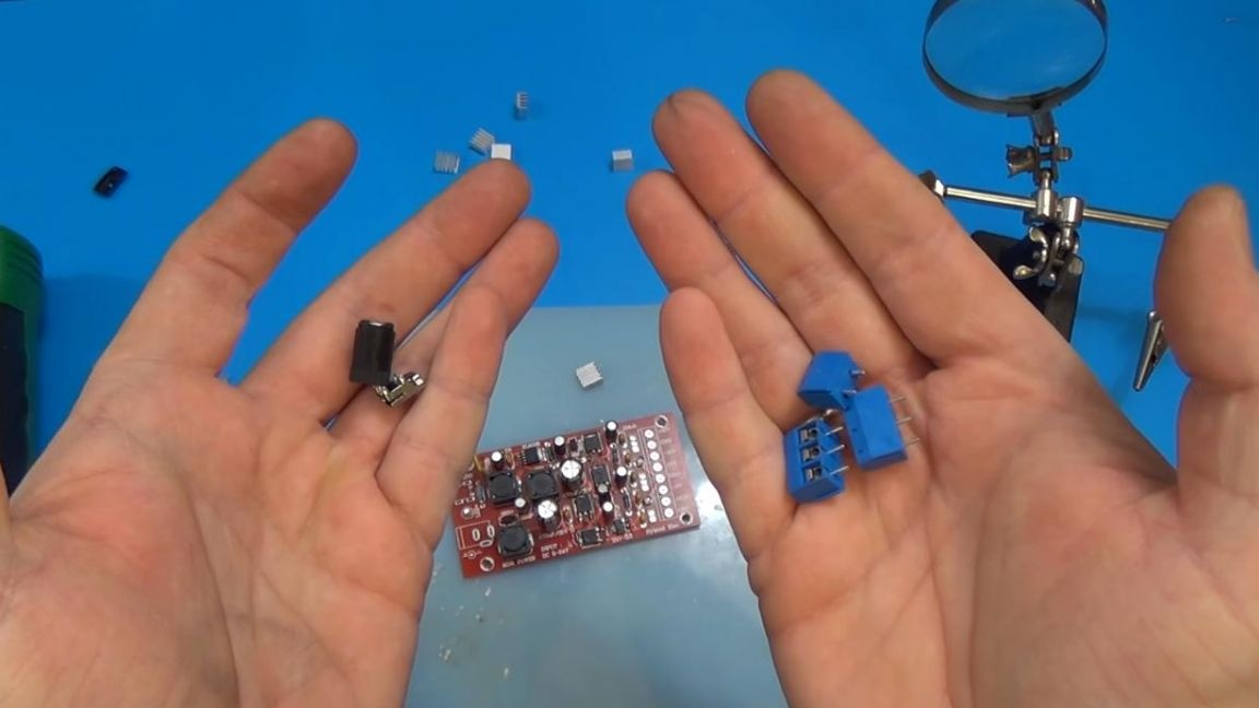
In order to assemble this converter, you will need:
* Kit-kit ordered in Ali
* Soldering iron, solder, flux
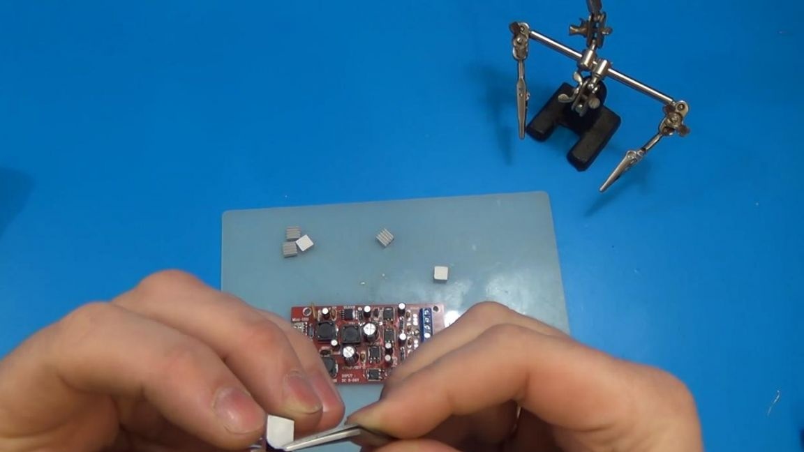
* Fixtures for soldering, such as "third hand"
* Side cutters
* Multimeter
Now let's move on to the assembly itself.
Step one.
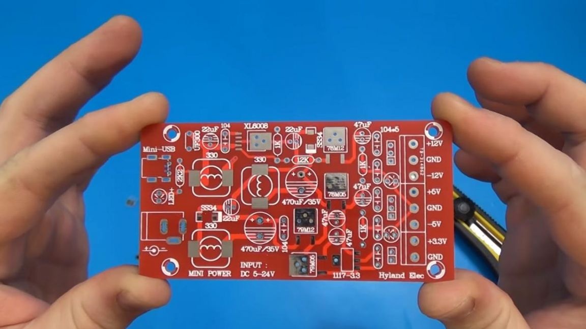
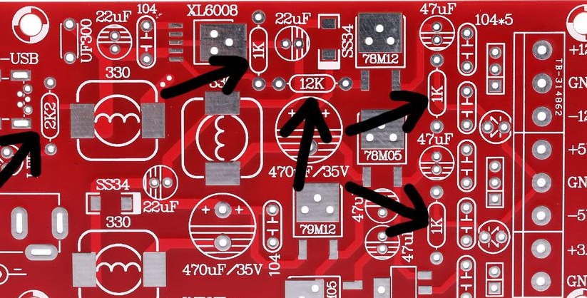
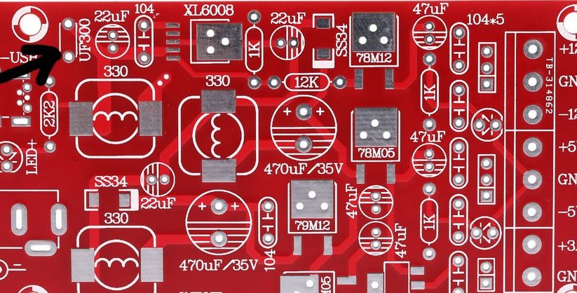
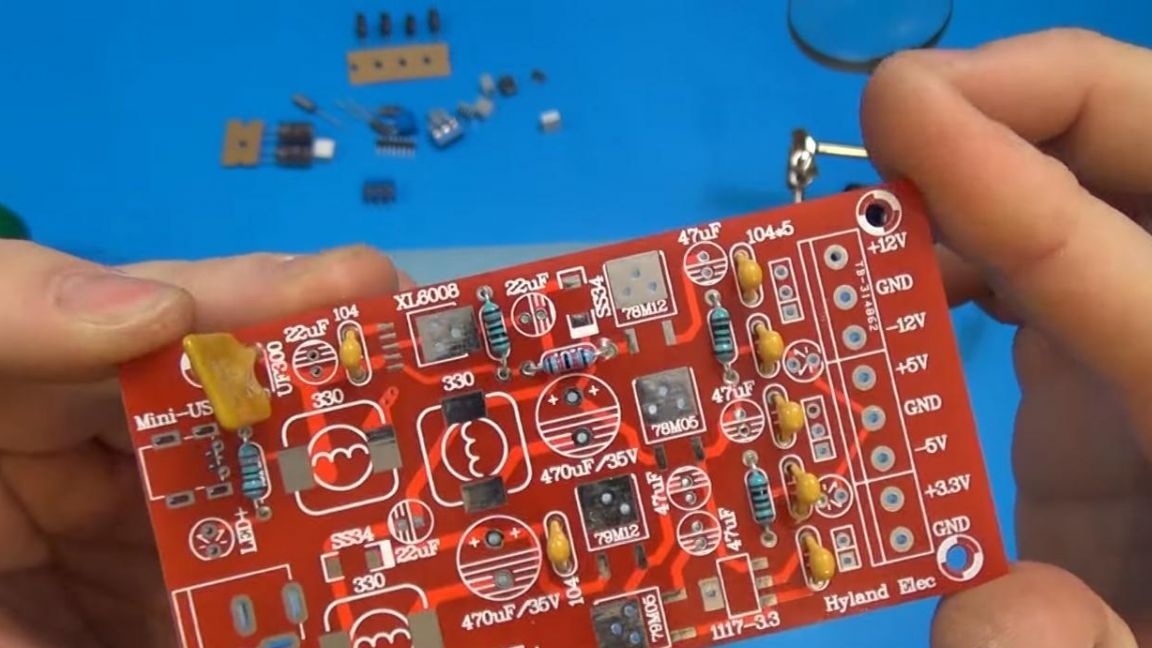
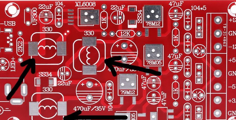
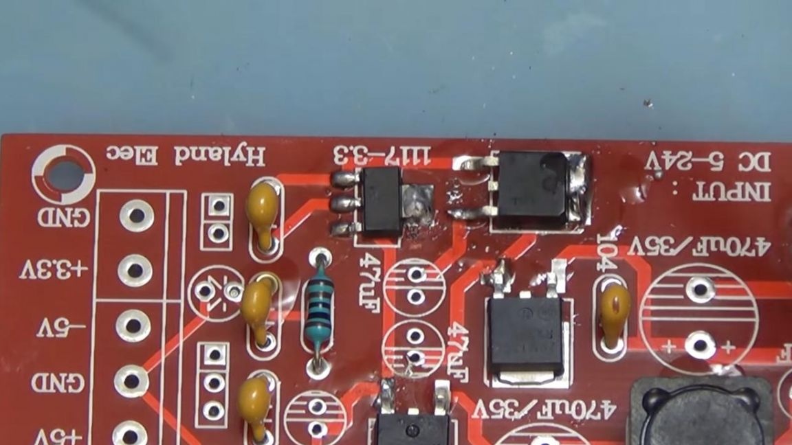
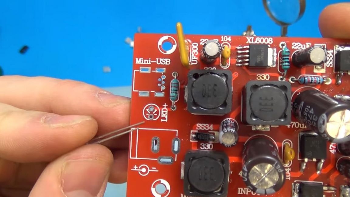
We turn on the soldering iron and start assembling with the resistors, on the board they are indicated by elongated ovals with the resistance designation, for example, an oval with the inscription 2k2 means that a 2.2kΩ resistor is installed here.
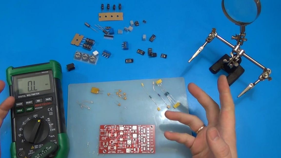
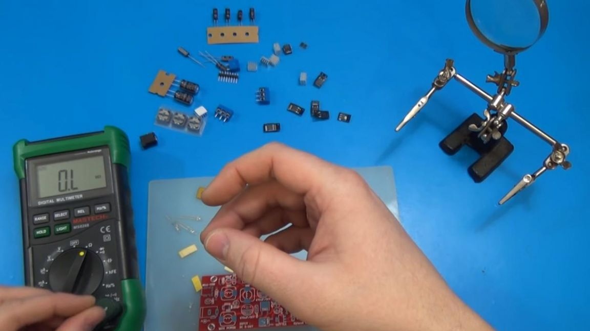
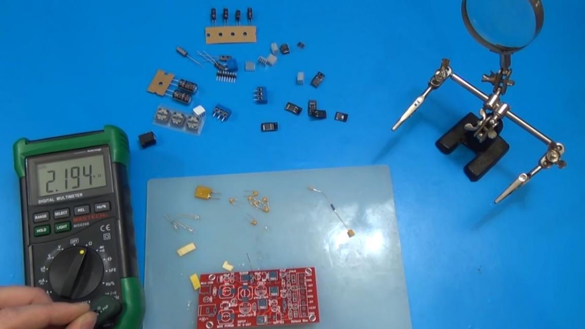
Several methods can be used to determine the resistance of each resistor. Using a multimeter, it is easy and quick to measure the resistance of a resistor, but if there is no multimeter, then the method for determining the resistance by color coding or an online calculator will be quite working.
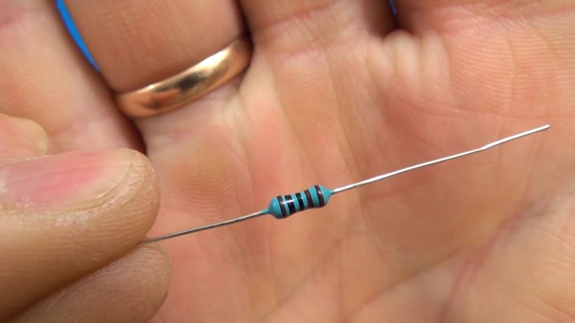
For convenience, I designated all 5 resistors that need to be soldered to the board, observing their ratings.
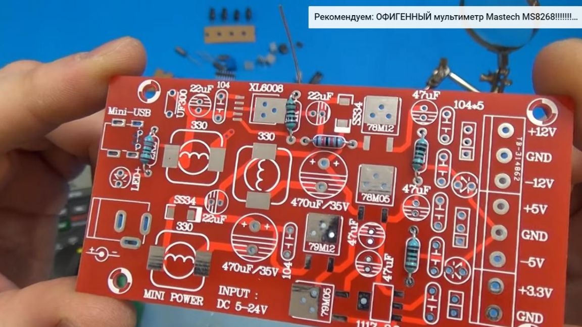
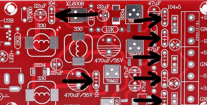
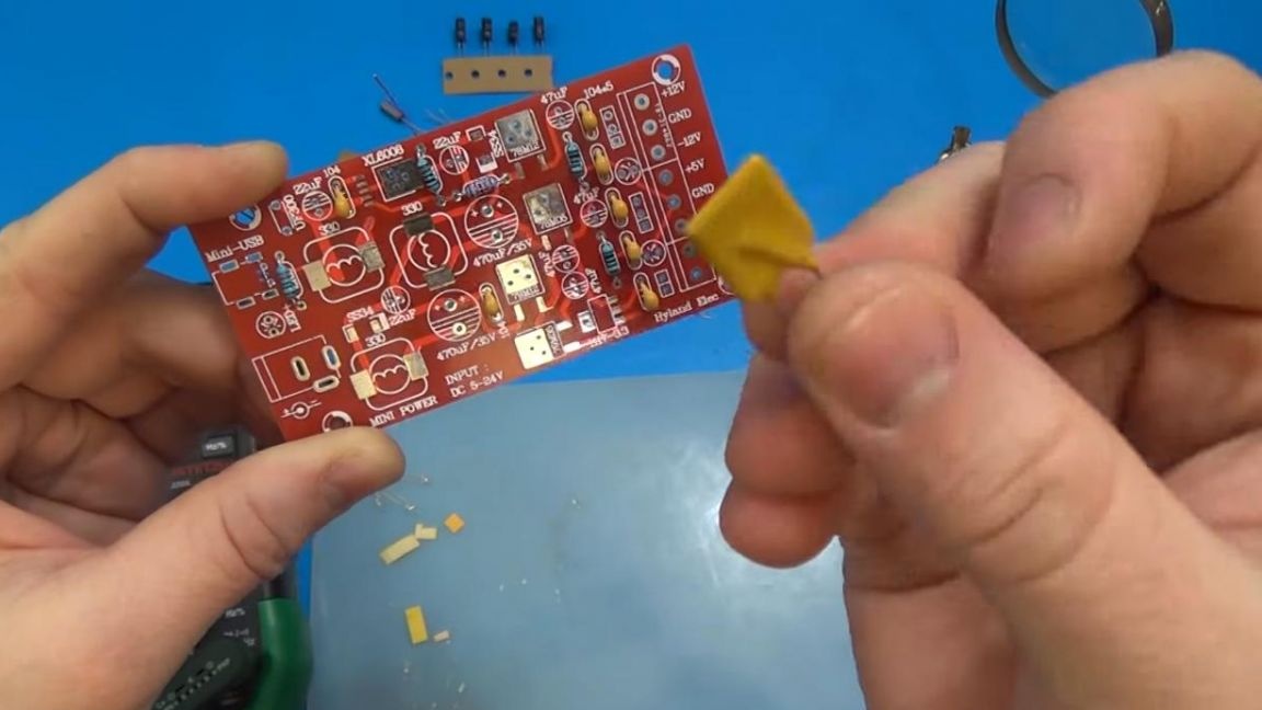
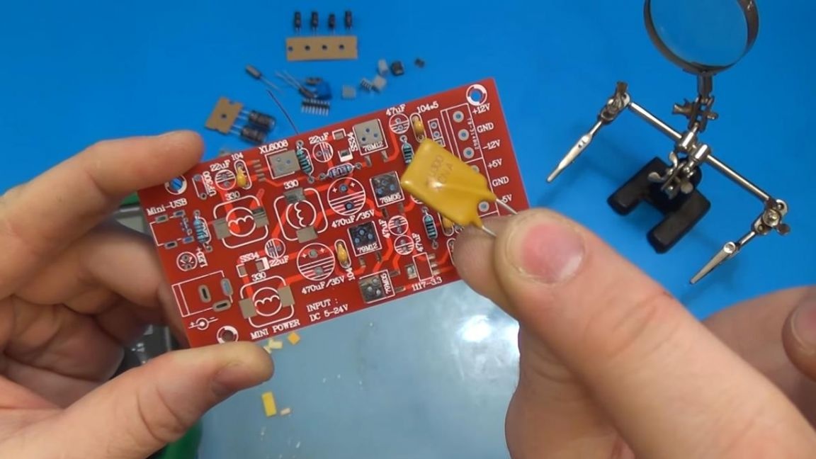
Next, you need to solder the ceramic capacitors, they are marked with the number 104, just like on the board. By the way, they do not have polarity, so the position of their contacts will not affect the operation of the circuit.
Step Two
After installing the non-polar capacitors, we turn to the fuse, in this circuit a self-healing fuse, designed for a current of 3A, is used. When the current reaches 3A, this fuse opens the circuit, and when the current decreases, it continues to operate. Install it on the board in the place designated UF300.
Step Three
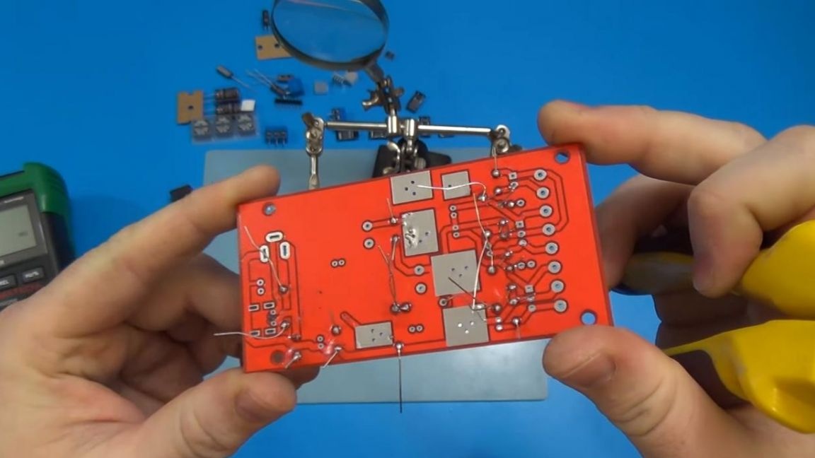
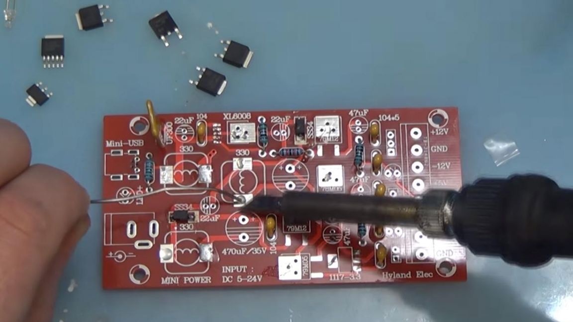
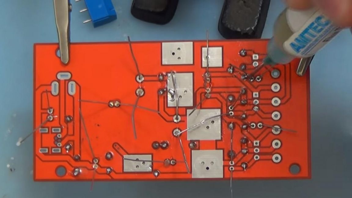
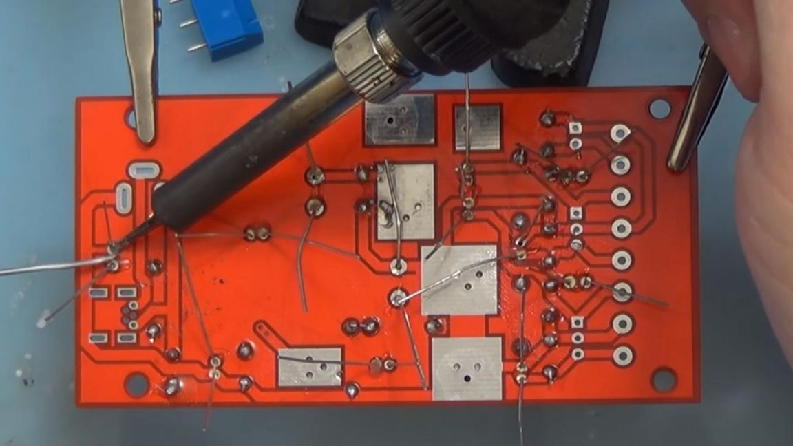
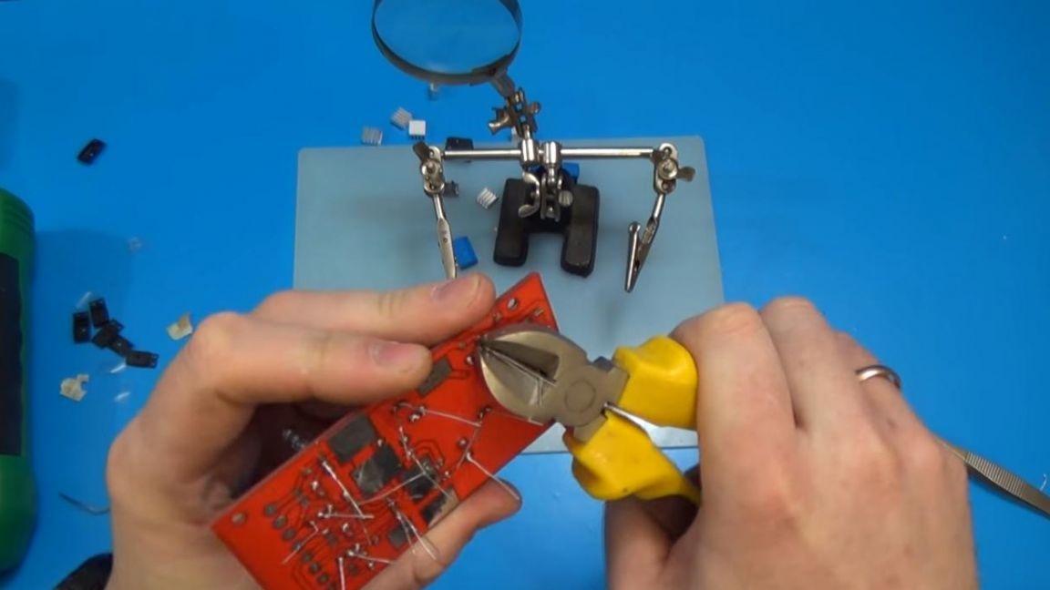
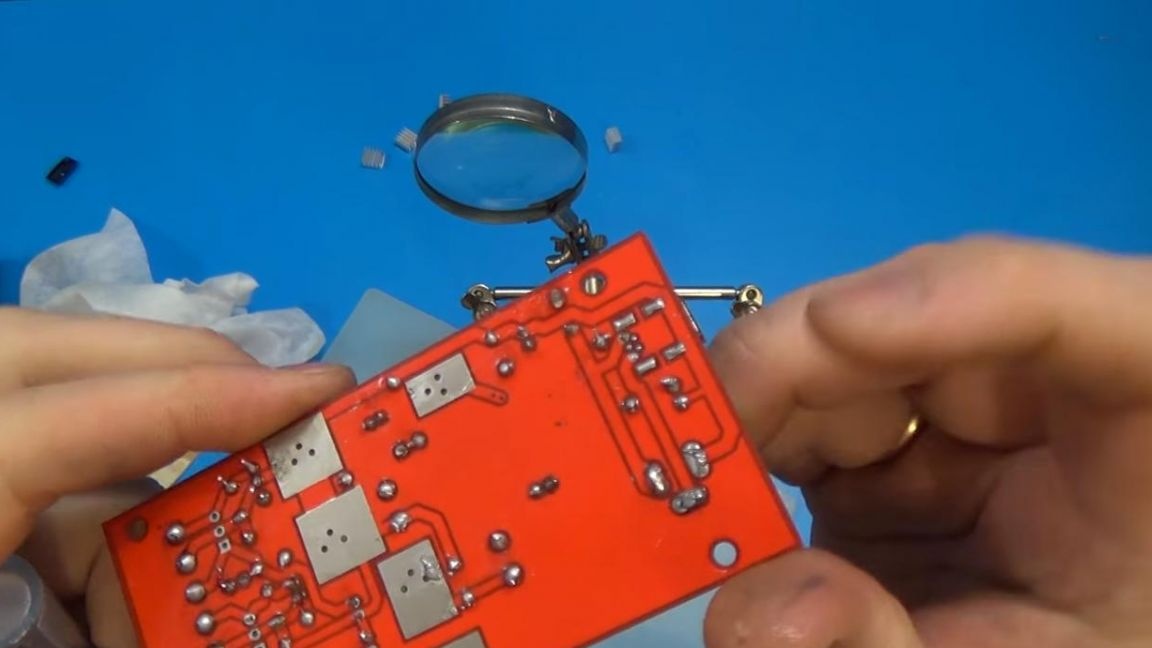
Now, using the "third hand", we fix the position of the board and solder the conclusions of the radio components to the pads using flux.
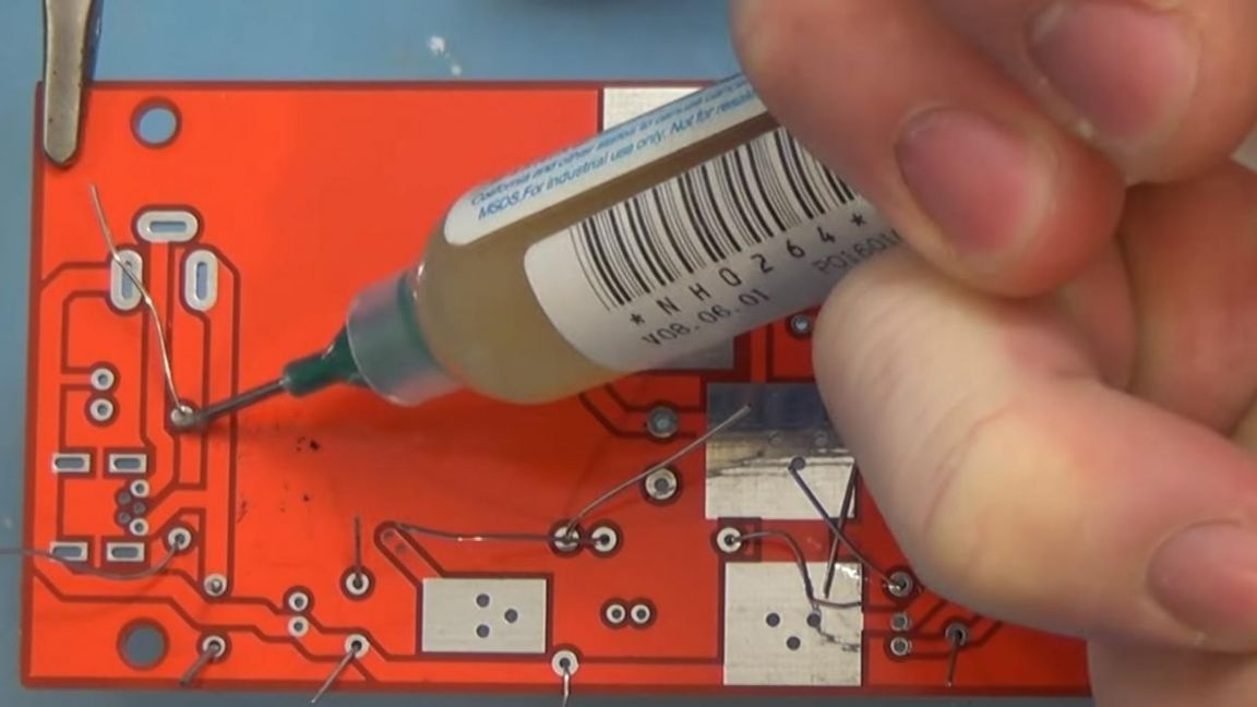
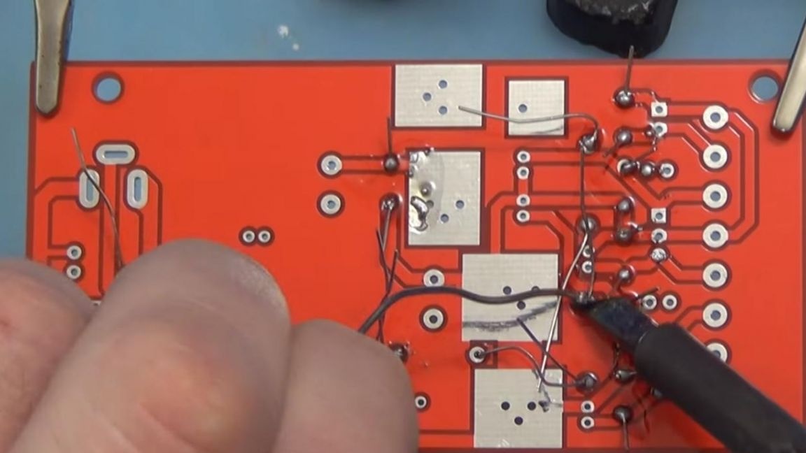
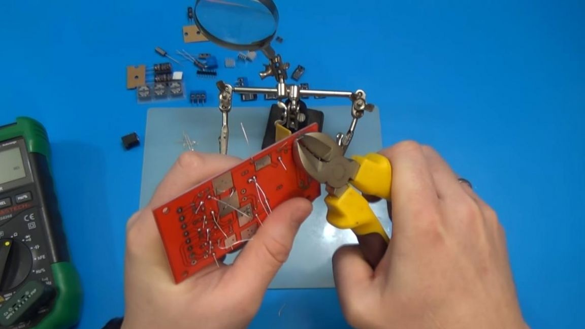
After soldering, we bite off the conclusions using side cutters, we do this carefully so as not to damage the tracks on the board.
Step Four
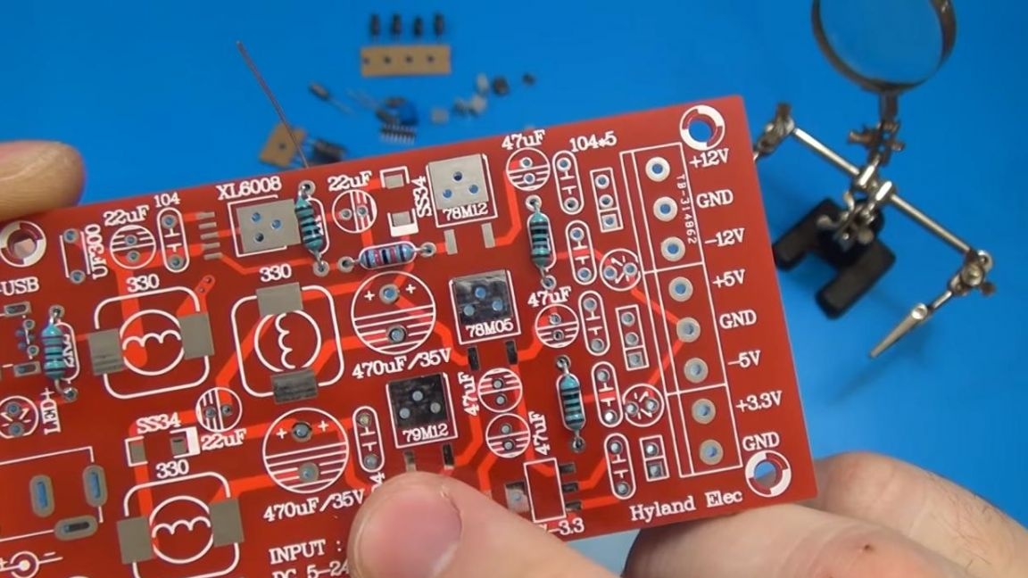
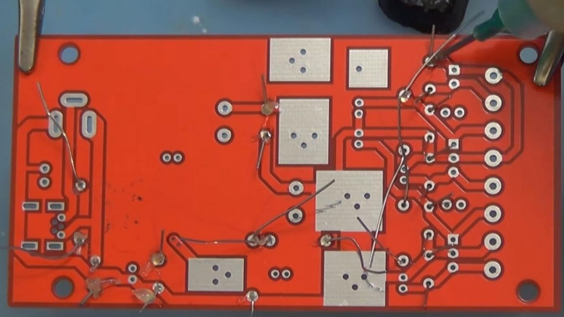
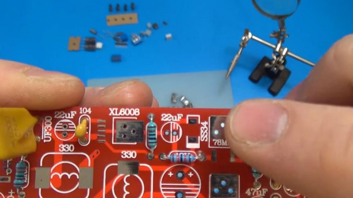
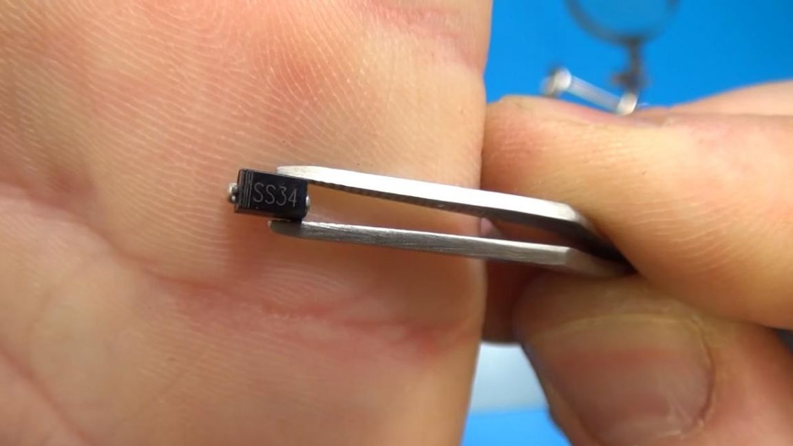
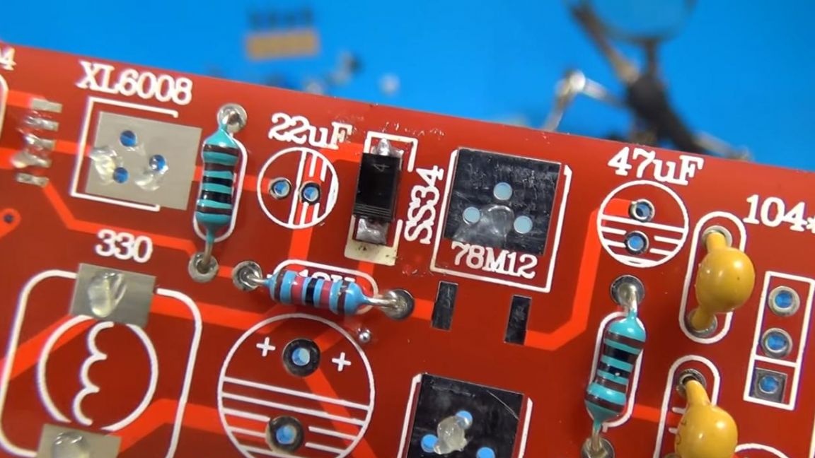
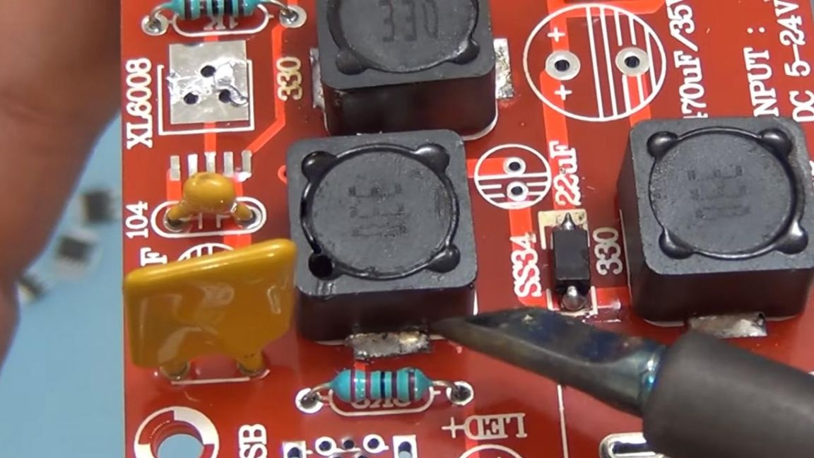
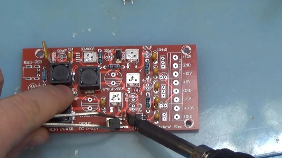
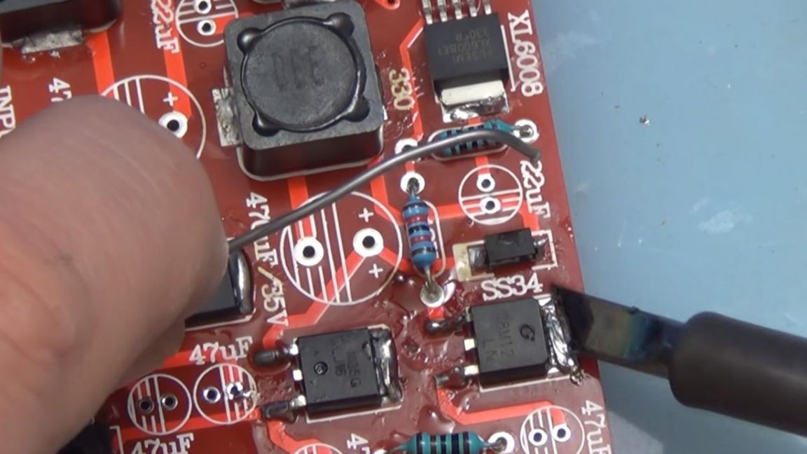
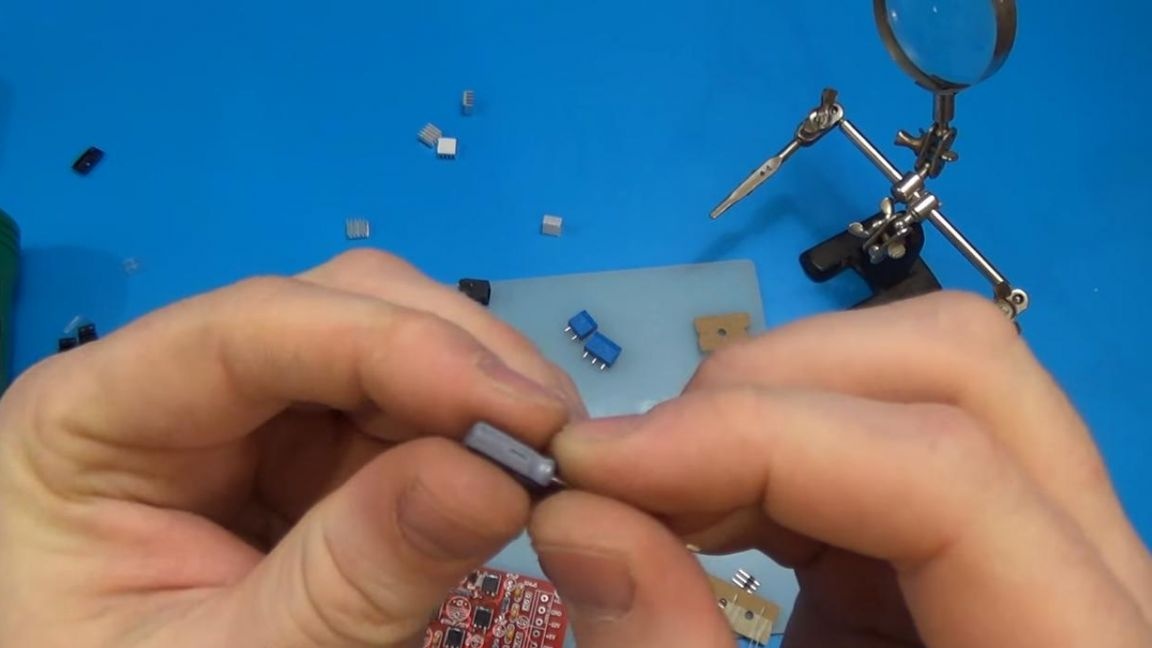
Our board also contains elements that need to be soldered from the front side, namely coils and regulators, the method of soldering is the same as when soldering SMD components. We apply flux to the board contacts and first of all solder the diodes, since it will be inconvenient to solder them after the installed inductors. The diodes are soldered as follows, the gray strip should coincide with the wide line, on the board are marked with the inscription SS34, there are only two on the circuit.
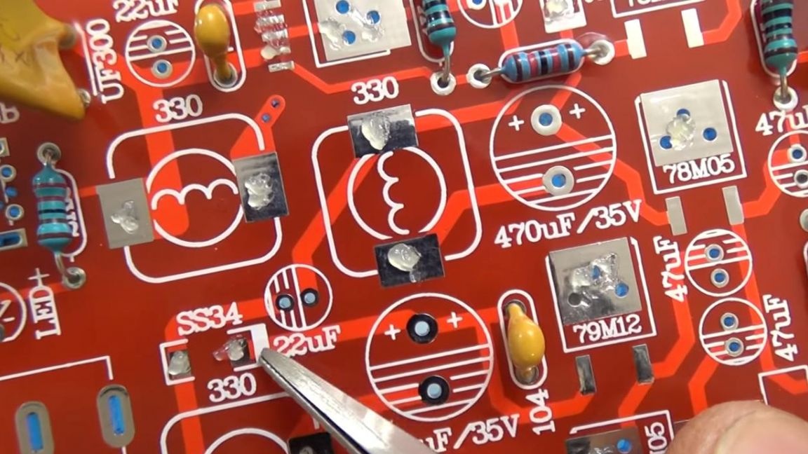
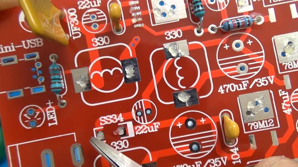
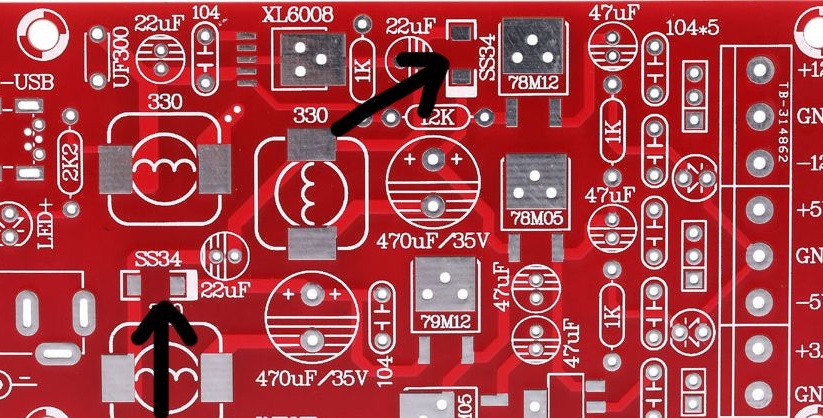
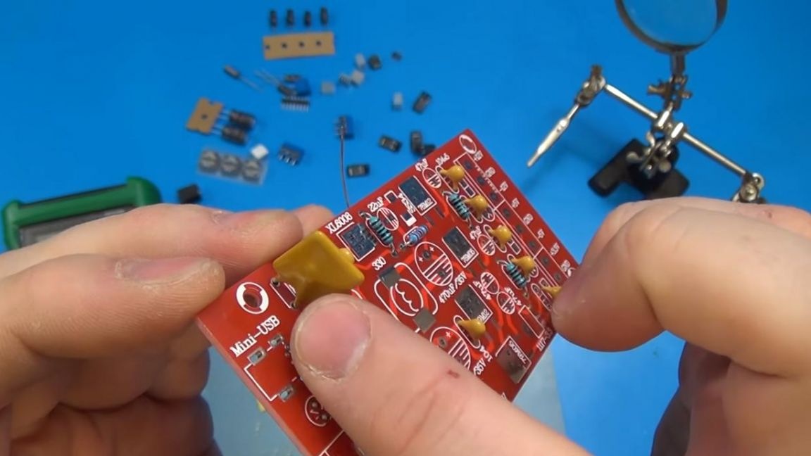
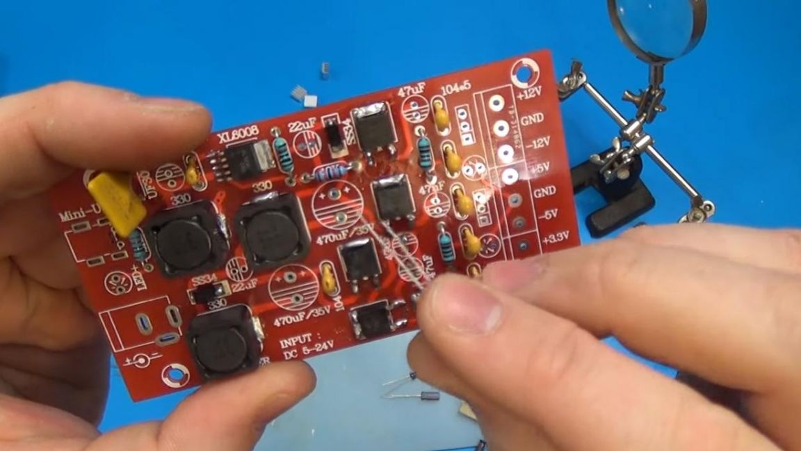
It should be something like in the photo.
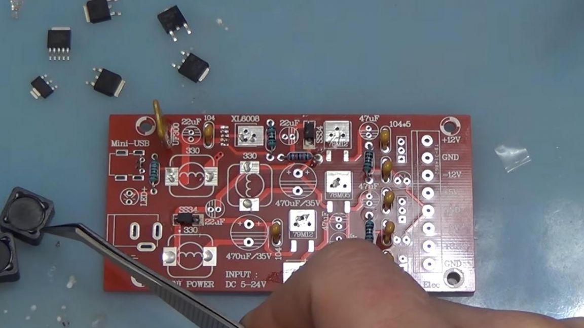
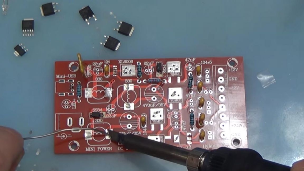
Next, we solder three inductors, they do not have polarity and are soldered in places with the image of a rounded square and a circle with a wavy line.
Step Five
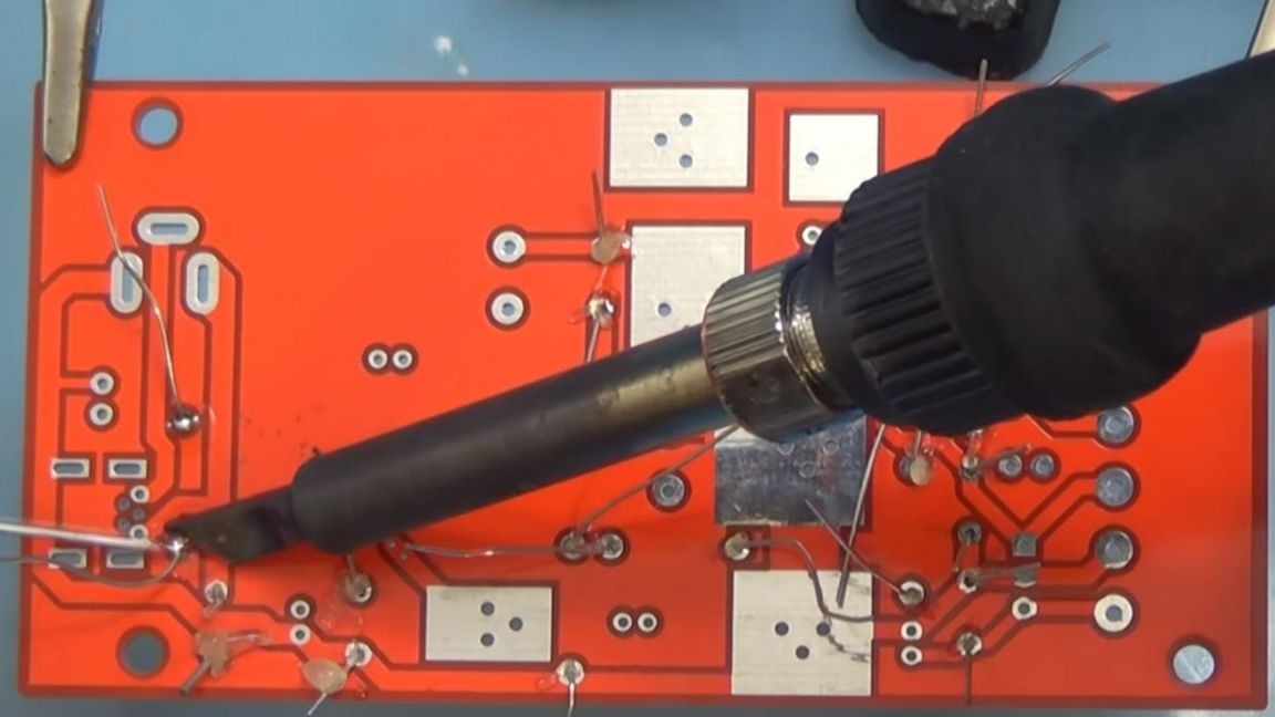
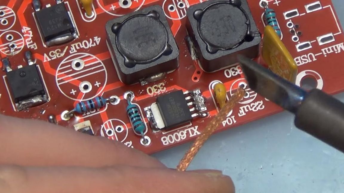
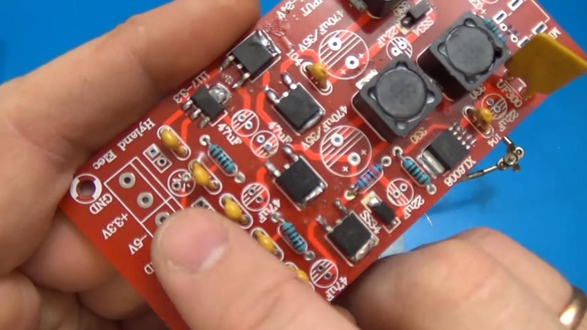
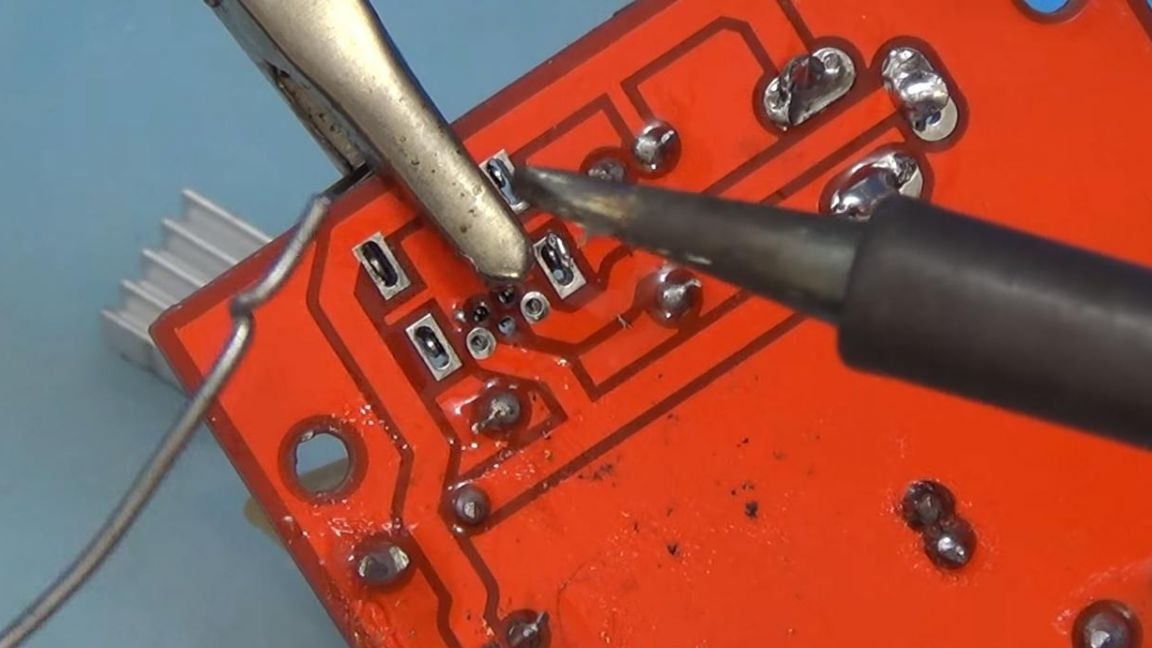
We solder the remaining components located on the front side, they are marked both on the case and on the board itself.
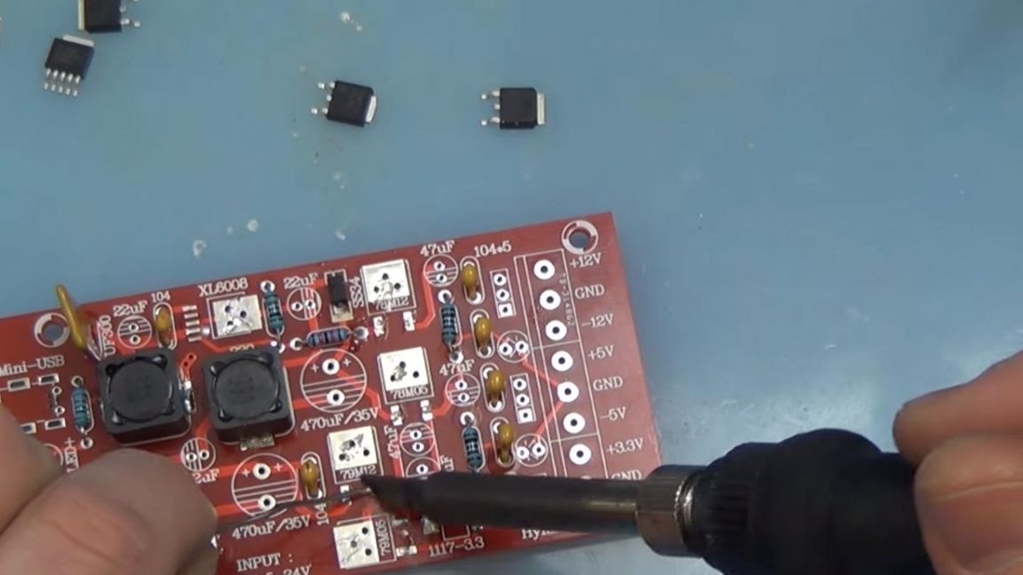
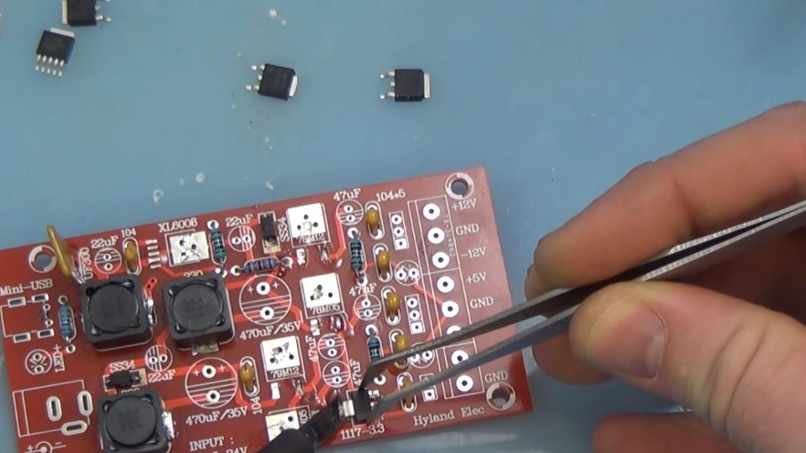
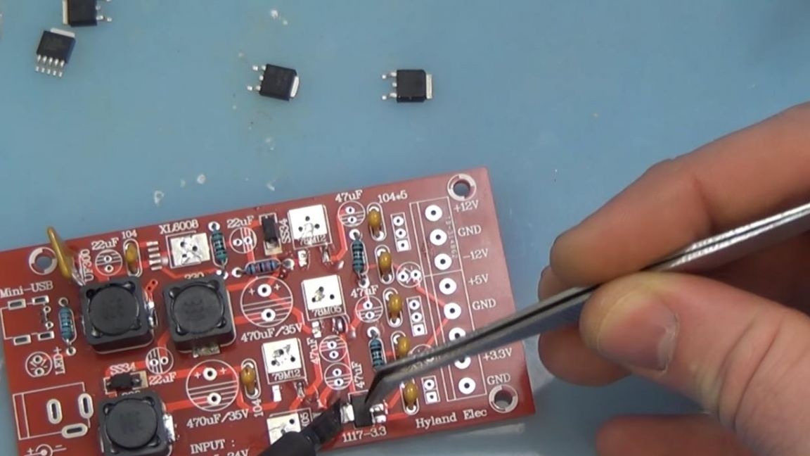
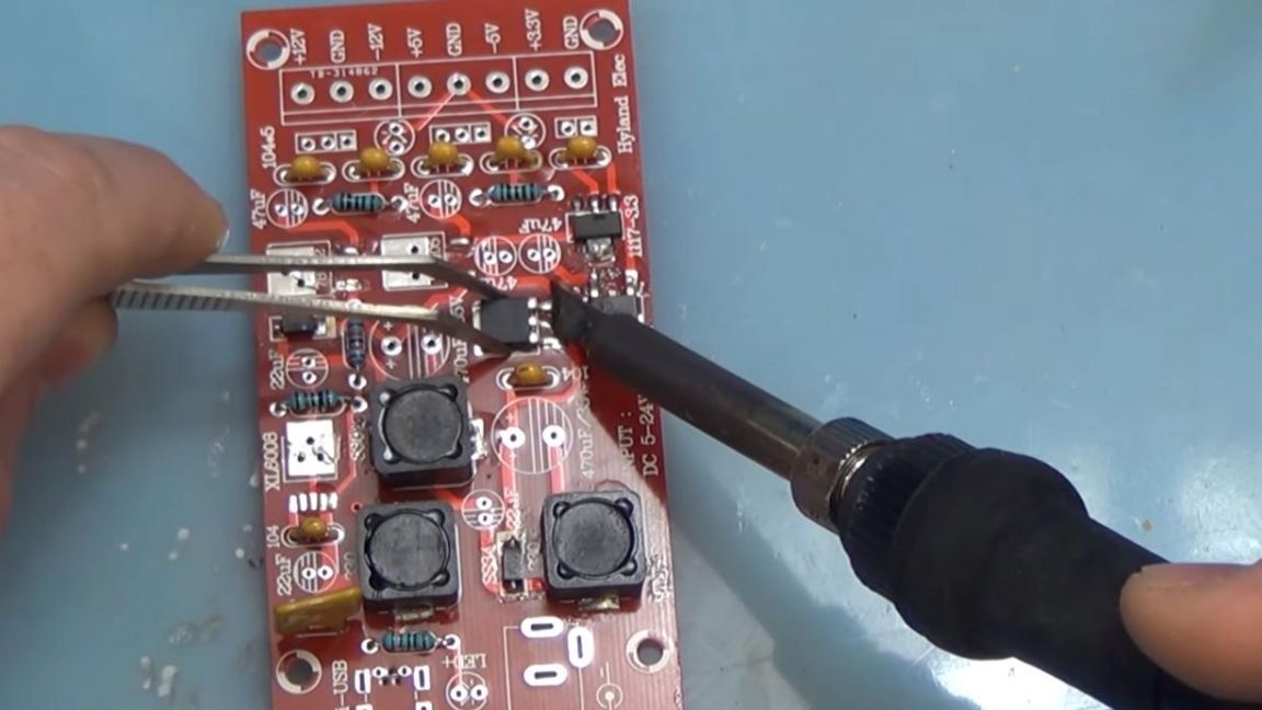
The main thing at this stage is not to overheat the legs, as this can lead to the failure of the microcircuit. Some legs on the microcircuits are located very close, so it may turn out that they are soldered together, this can be eliminated easily using a special screen that absorbs excess solder.
Step Six
Next, we install electrolytic capacitors, plus this is a long terminal, minus short, also the negative contact is shown on the case.
The polarity on the LEDs is determined in the same way. The capacitors are signed on the board, so we solder them, observing the marking. After installing the capacitors, we solder the LEDs, plus on the board it is shown in the form of a triangle, minus in the form of a strip, you can still install the LEDs according to the slice made on its case and marking on the board.
Apply flux and solder the conclusions.
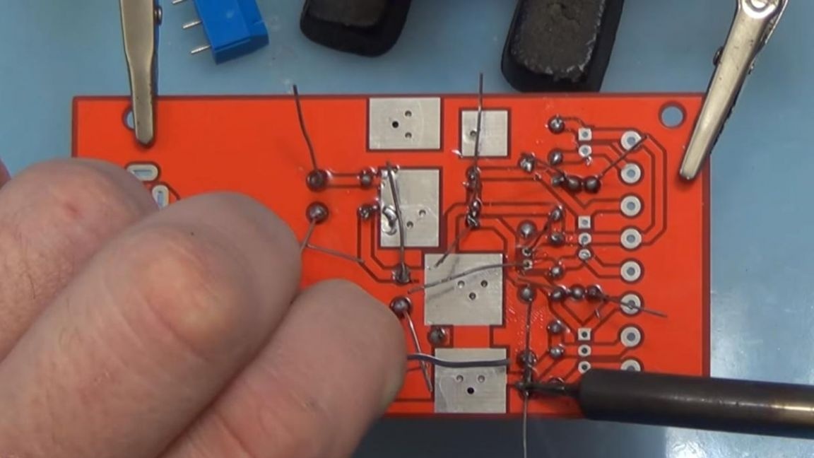
And also observing accuracy we remove the excess remains of conclusions with side cutters.
Seventh step.
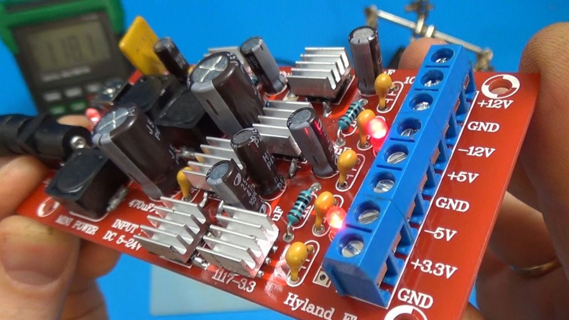
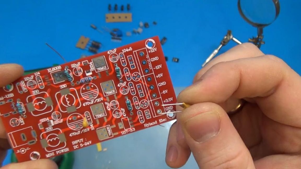
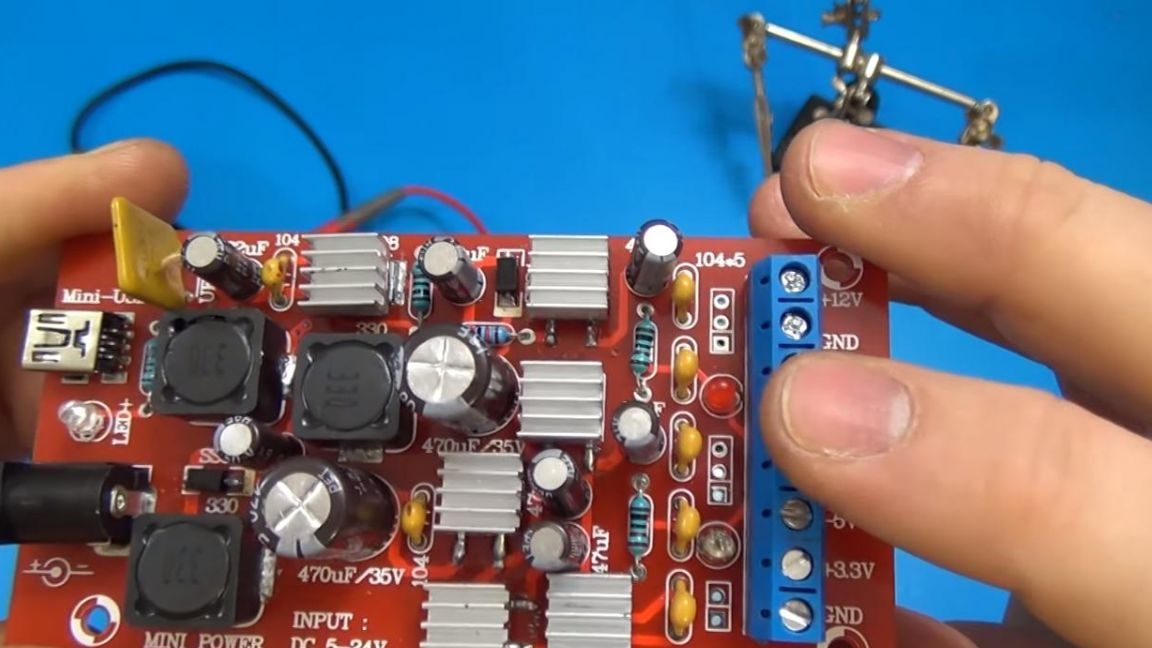
It remains quite a bit, namely to solder the power supply connectors and power output pads. The device is powered by both micro usb and 5.5mm jack.
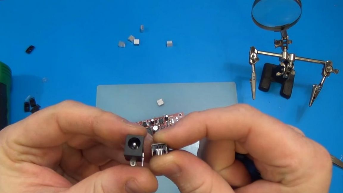
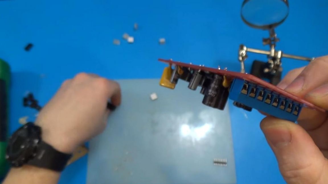
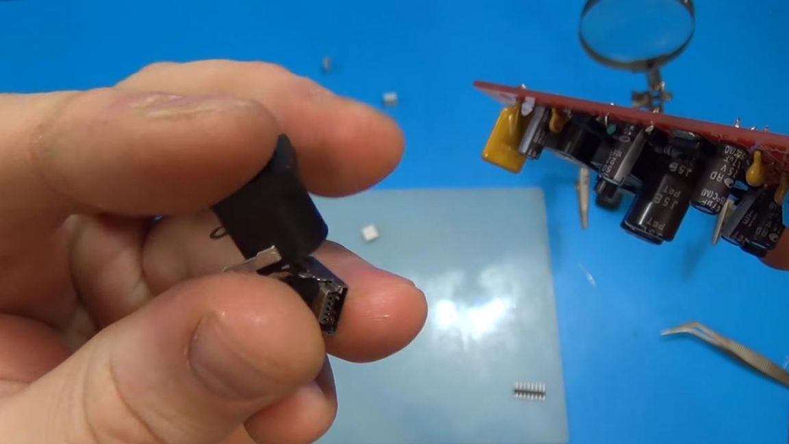
We solder them to the board, before that we connect the pads together, as a result, one length is obtained. In this block, the pins are quite thick, so it’s better to use a more powerful soldering iron to solder it. At the end, we install aluminum radiators on the microcircuit, since they heat up during operation.
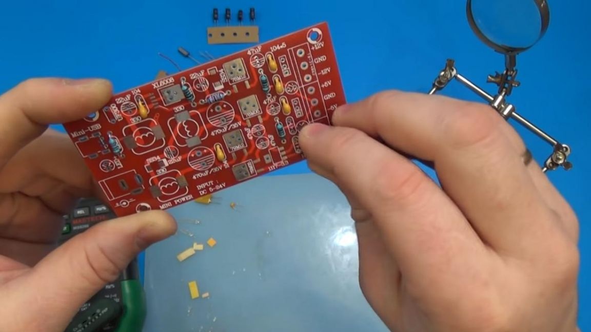
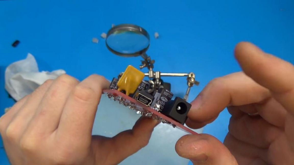
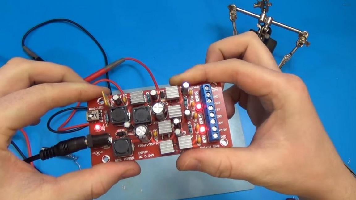
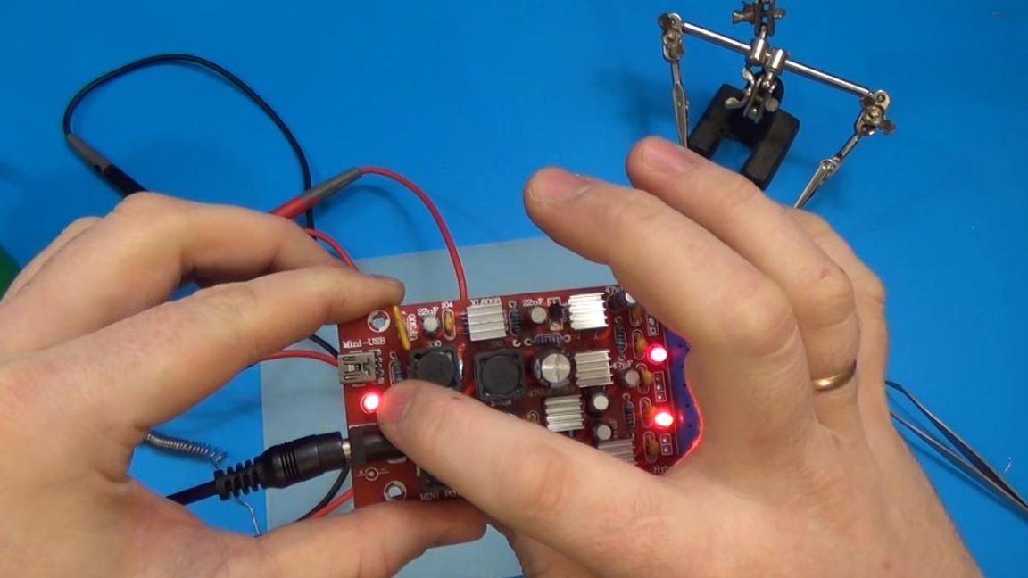
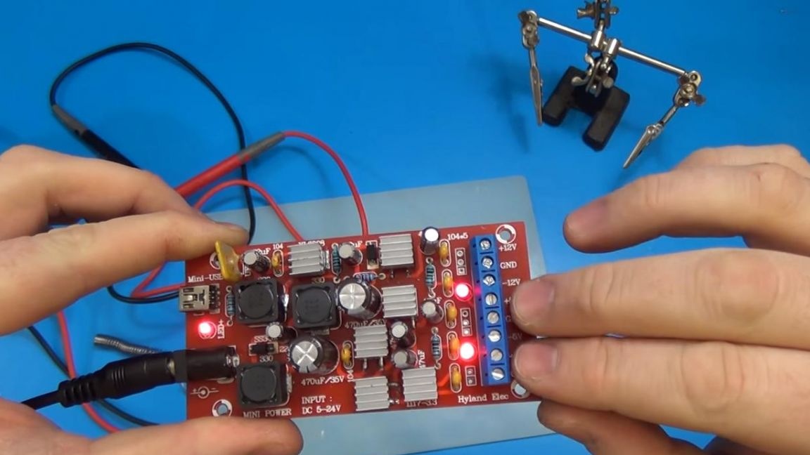
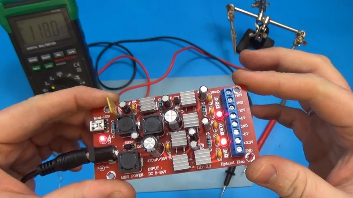
On this assembly, the transducer from the kit kit is completed, the only thing left to do is to check the operability. We supply 9 volts to the 5.5 mm plug, three LEDs show that the board is working, namely, one LED informs that there is power at the input and two LEDs that there is voltage at the outputs of the 5 volt line.
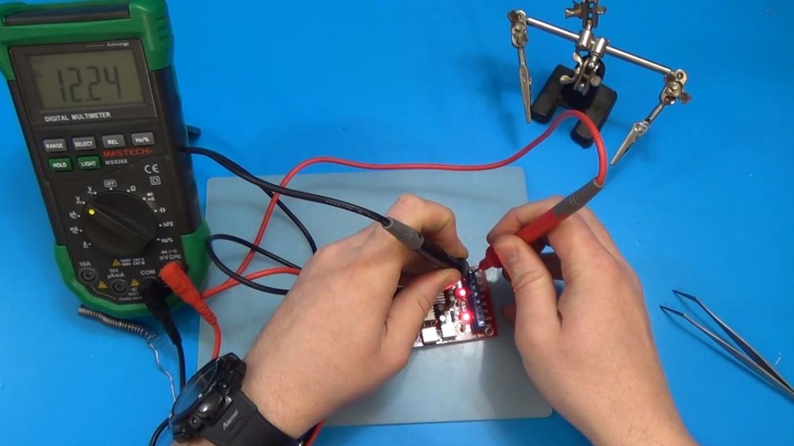
Here are the data from the multimeter.
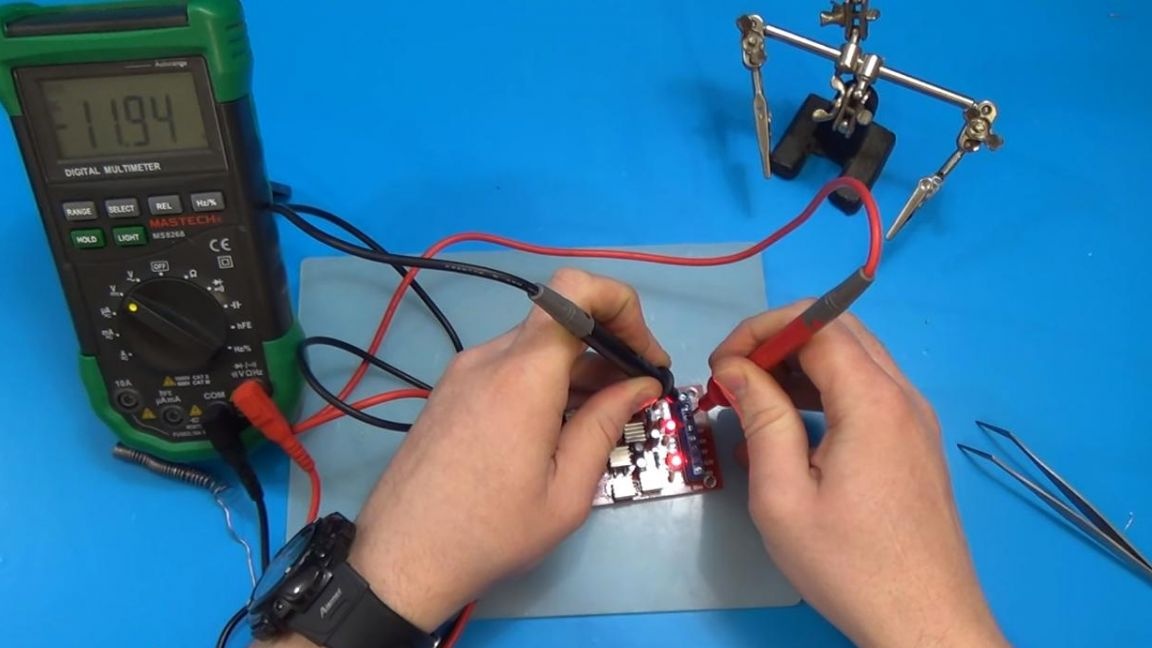
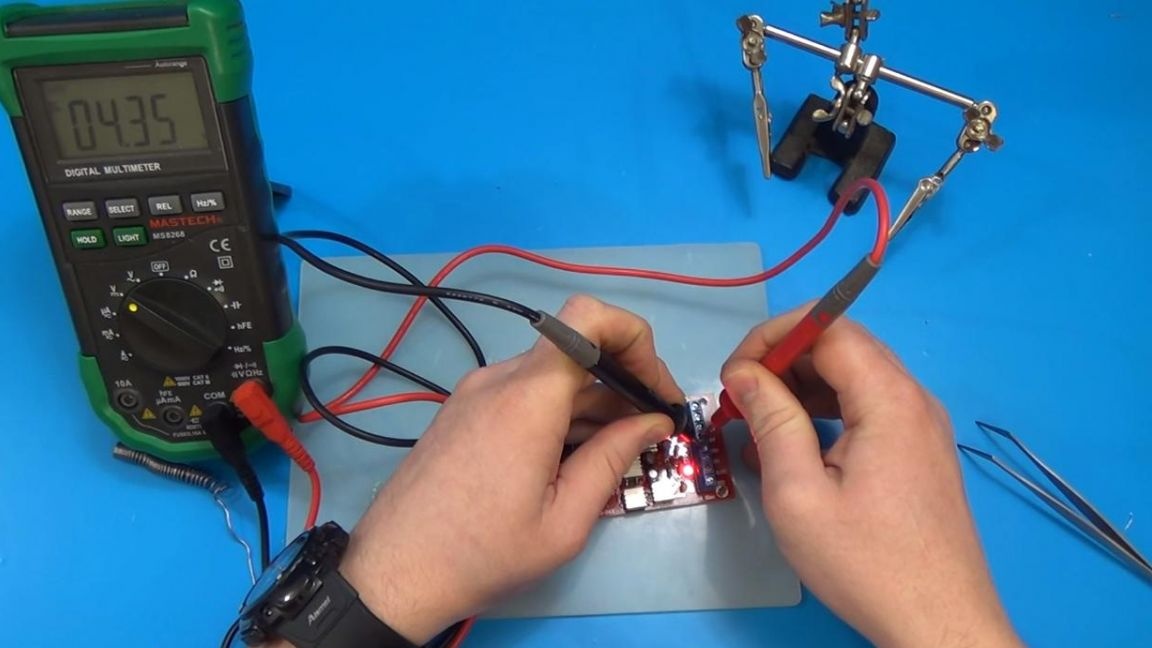
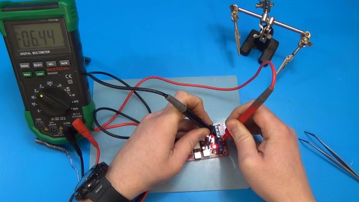
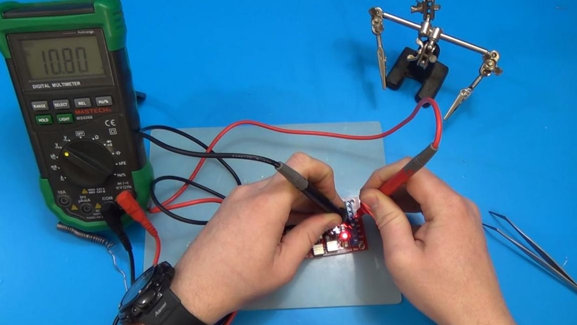
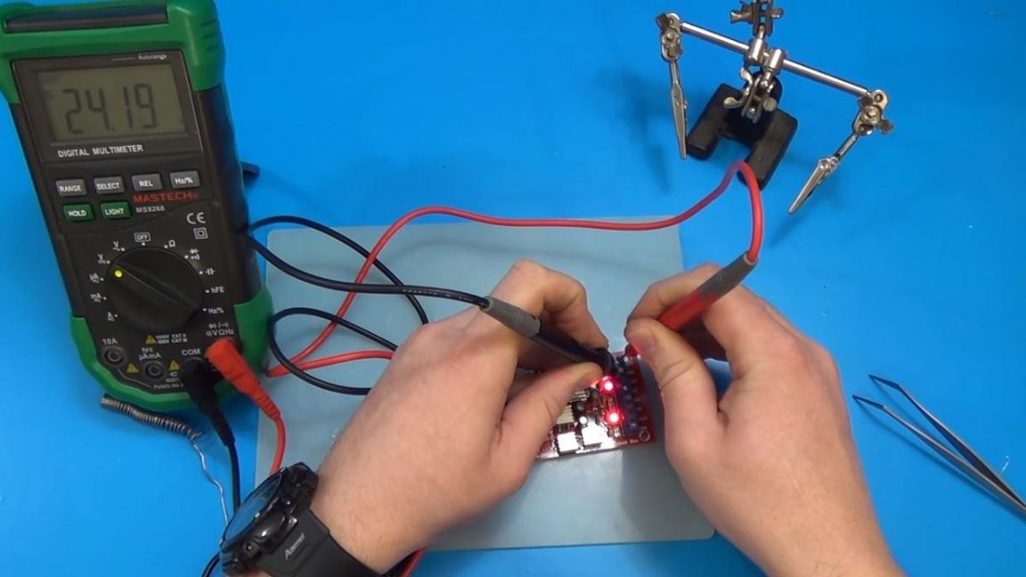
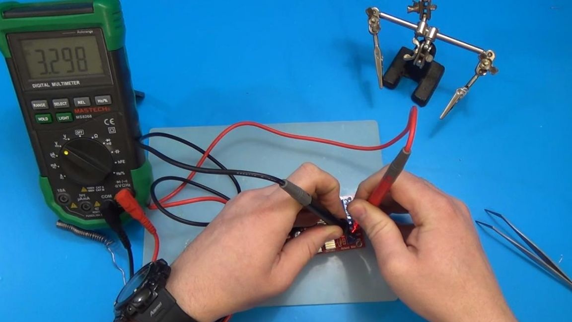
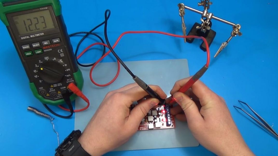
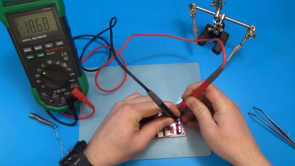
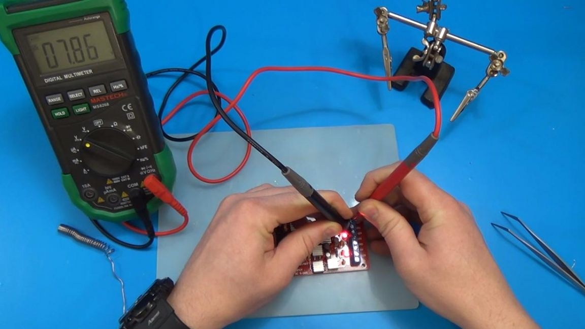
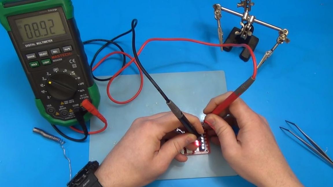
It is also possible some combination of conclusions, you can get at the same time 18, 8 and 9 volts, in addition to the standard 12 +, 12-, 5+, 5- and 3.3 volts.
Thank you all for your attention and successful assembly of kit-kits.