
Parts and Tools
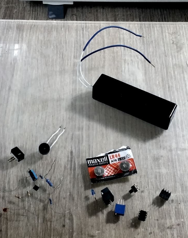
Some of them are optional, due to unnecessary functions (such as an on / off LED indicator). But it looks prettier, so it is recommended to add them.
Integrated Circuits:
• 1 x LM358 Operational Amplifier
• 1 x LM555 timer circuit
Resistors:
• 1 x Trimmer 10kom
• 2 x 10kom
• 1 x 22kom
• 2 x 1kom
• 1 x 220Ohm
Capacitors:
• 1 x 0.1 UF ceramic
• 1 x 100uF Tantalum
Other Components:
• 1 x imp-2B2E Schottky diode (you can use any diode with a small voltage drop)
• 1 x 2N2222A or similar transistor - low-voltage signal converter
• 1 x LED blue color
• 1 x buzzer
• 2X 1.5V Batteries
Mechanics and interface:
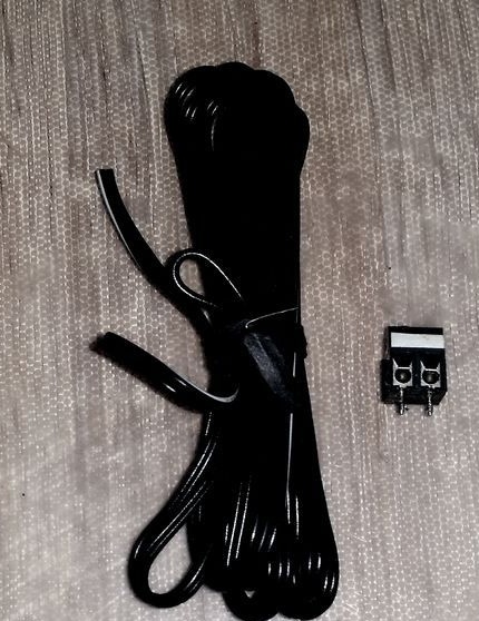
• 1 x 2 Contact Terminals
• 2 x contact wires
Schemes and operations
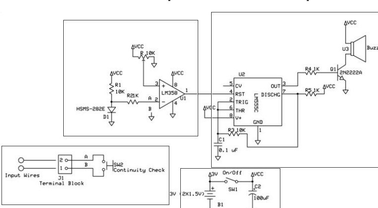
To understand the operation of the circuit, we divide the circuit into three parts. Each part corresponds to a separate block operation.
A. Comparison and explanation:
In order to check the continuity of the wire, there you need to connect an electric circuit, current will flow through the wire. If the wire is faulty, there will be no voltage, while the current will be zero. The principle of the circuit is based on the method of comparing the voltages between the reference voltage and the voltage drop across the wire.
Input cables connect to the terminal block, it is much easier to change the cable. It is connected at the points designated as "A" and "B" in the diagram, where "a" is the phase and "B" is zero. As can be seen from the diagram, when there is a gap between “A” and “B”, the voltage drop will occur on the “A” component gap, so the voltage on “A” becomes greater than on “B”, thus, the comparator will produce 0V output. When the test wire is shorted, the voltage will be 0V at “a” and the comparator will produce 3V (VCC) at the output.
Since the tested conductor can be of any type: PCB trace, power lines, ordinary wires, etc. There is a need to limit the maximum voltage drop across the conductor if we do not want to burn components. Diode D1 through a 10K resistor, maintains a constant voltage of ~ 0.5 V, the maximum voltage that may be present on the conductor at the output. The LM358 op-amp is used as a comparator in this circuit.
B: generator output signal:
A circuit has two states, which can be by definition: either a “short circuit” or a “break”. So, the output of the comparator is used as an enable signal from a 1 kHz square wave generator.The LM555 chip (available in a small 8-pin package) is used to provide such a wave where the comparator output is connected to the LM555 reset pin (i.e., the enable chip). Resistors and capacitor values of 1 kHz square wave, in accordance with the manufacturer's recommended values. The output of the LM555 is connected to an NPN transistor used as a switch, which allows the buzzer to provide an audio signal at the appropriate frequency, each time a “short circuit” occurs.
C. Power Supply:
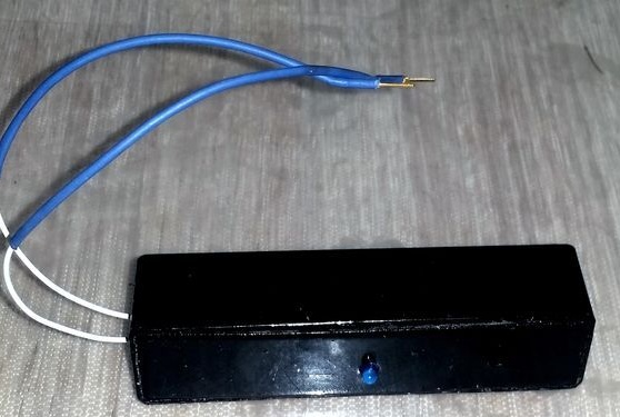
In order to make the device as small as possible, two 1.5 V batteries are used in the series. Between the battery and the VKK there is an on / off button. A tantalum 100μf capacitor is used as the regulating part.
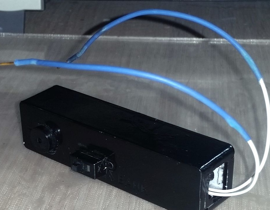
Soldering and assembly
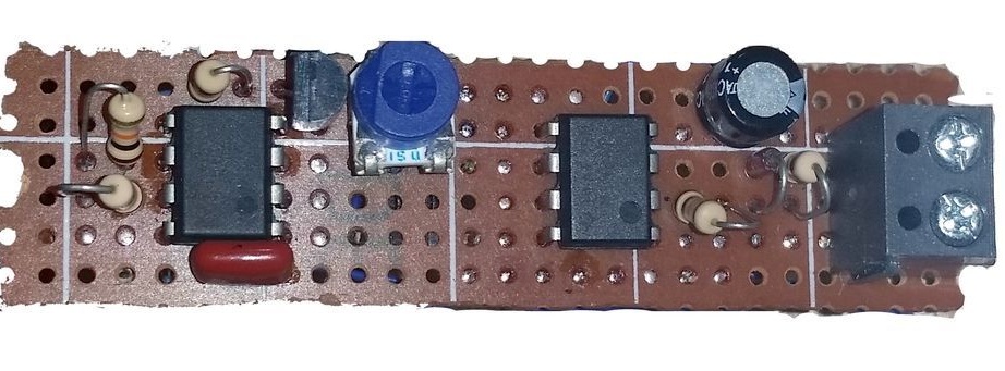
As you can see in the first picture, to make the device as small as possible. Thus, all microcircuits, resistors, capacitors, and a trimmer in the terminal block are sealed very close to each other, depending on the size of the case (depending on the total size of the case).
Testing
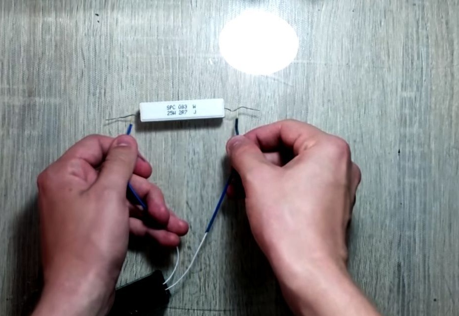
Now that the device is ready for use, the last step is to calibrate the device for a “short circuit”. In order to determine the threshold resistance.
Calibration algorithm simple, the resistance threshold can be obtained from a set of relations:
V [+] = Rx * VCC / (Rx + Ry),
Dimensions V [Diode]
V [-] = V [Diode] (current on the op-amp can be neglected).
Rx * VCC> Rx * V [D] + Ry * V [D];
Rx> (Ry * V [D]) / (VCC - V [D])).
This is the minimum resistance of the device under test, calibrated to 1st or lower, therefore the device will indicate as a “short circuit”.