
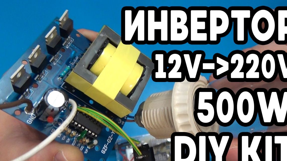
Hello to all lovers of radio designers and those who are interested in radio electronics. In this article I will tell you how to make an inverter that increases the voltage from 12 volts to 220, as well as 380 volts, which can be useful in future homemadeneeding a high voltage in the role of food, everything will be assembled with the help of a kit kit, which can be ordered in China on Ali.
Before reading the article, I suggest watching a video where the assembly and a small test of the already assembled inverter are shown.
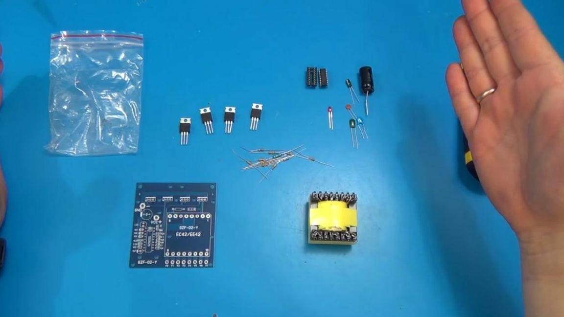
In order to assemble this inverter, you will need:
* Kit-kit ordered in Ali
* Soldering iron, solder, flux
* Power button and two wires
* Side cutters
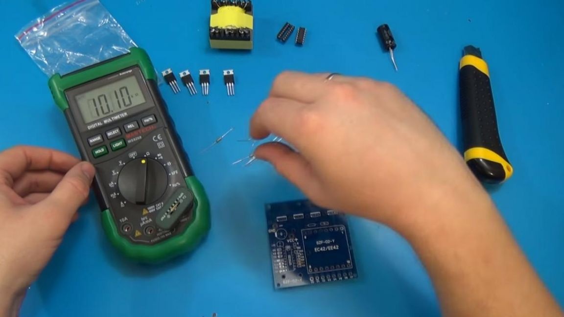
* Multimeter
* 220 volt lamp for checking
* Laboratory power supply
Let's proceed to the assembly of the kit.
Step one.
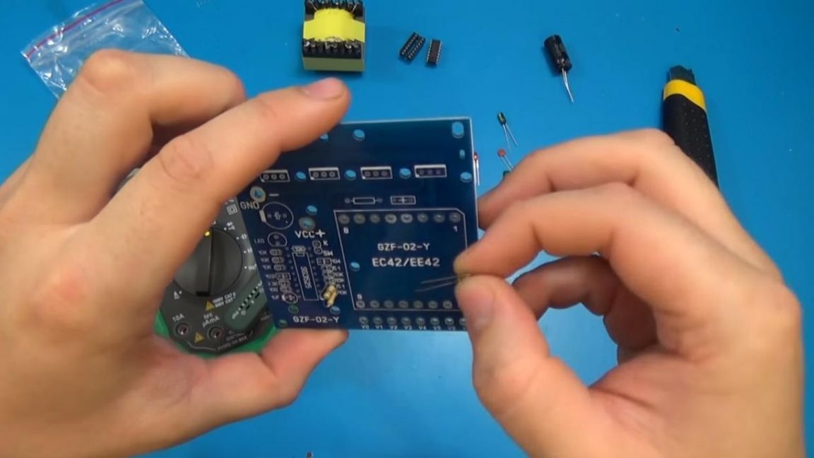
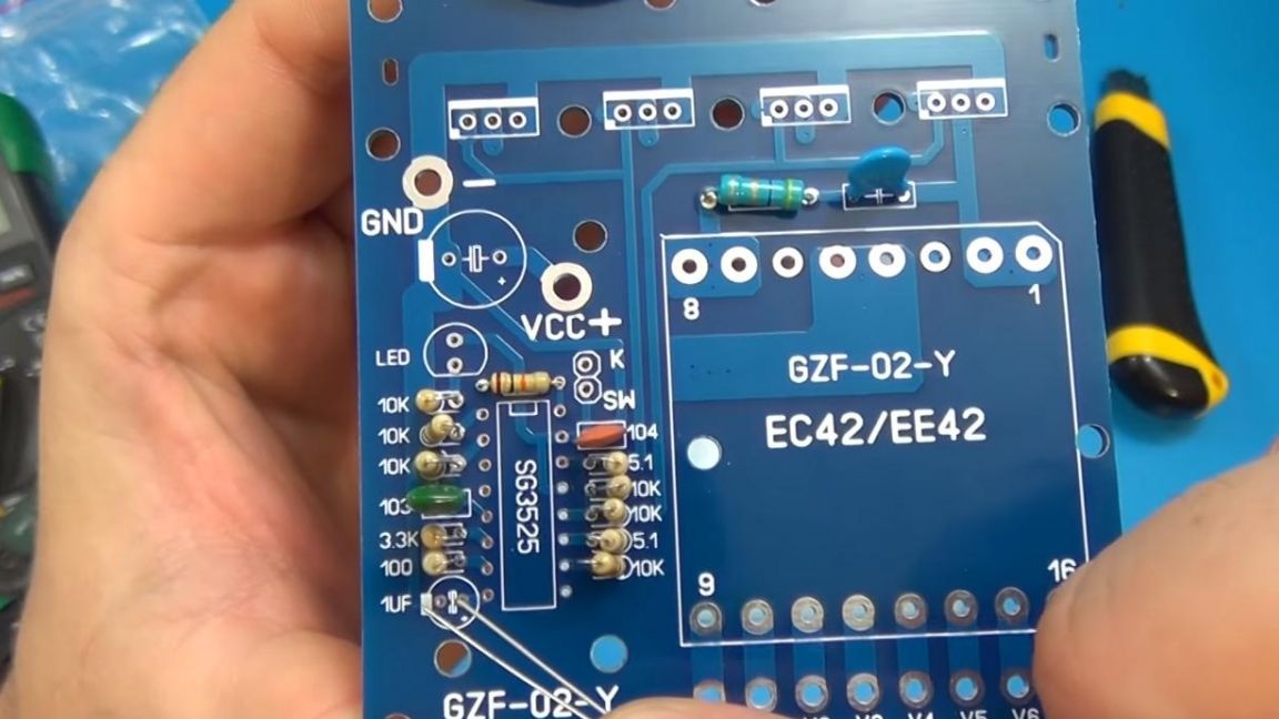
We put the soldering iron to heat up, and while it is gaining temperature, we determine the resistance of the resistors and set by marking.
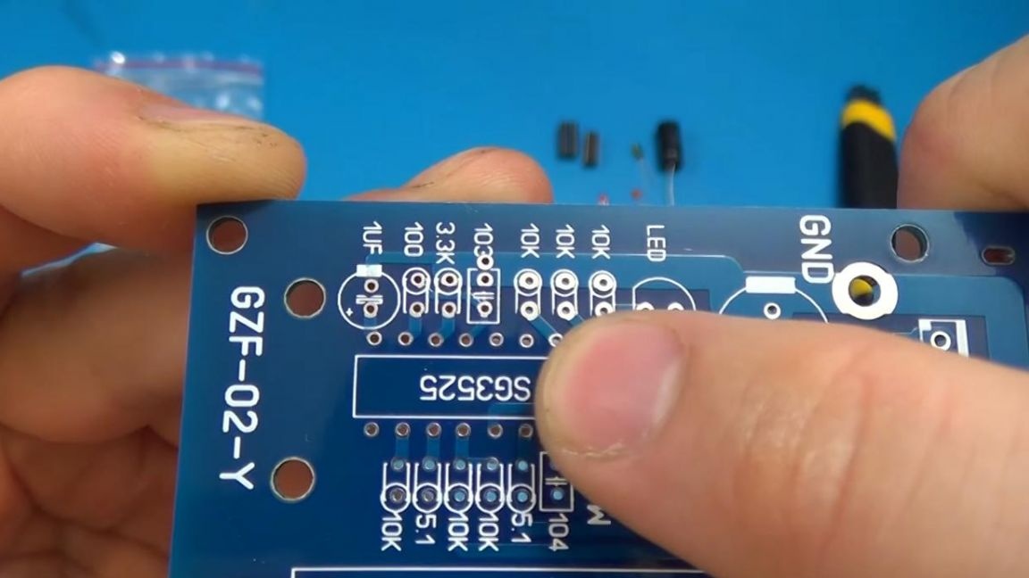
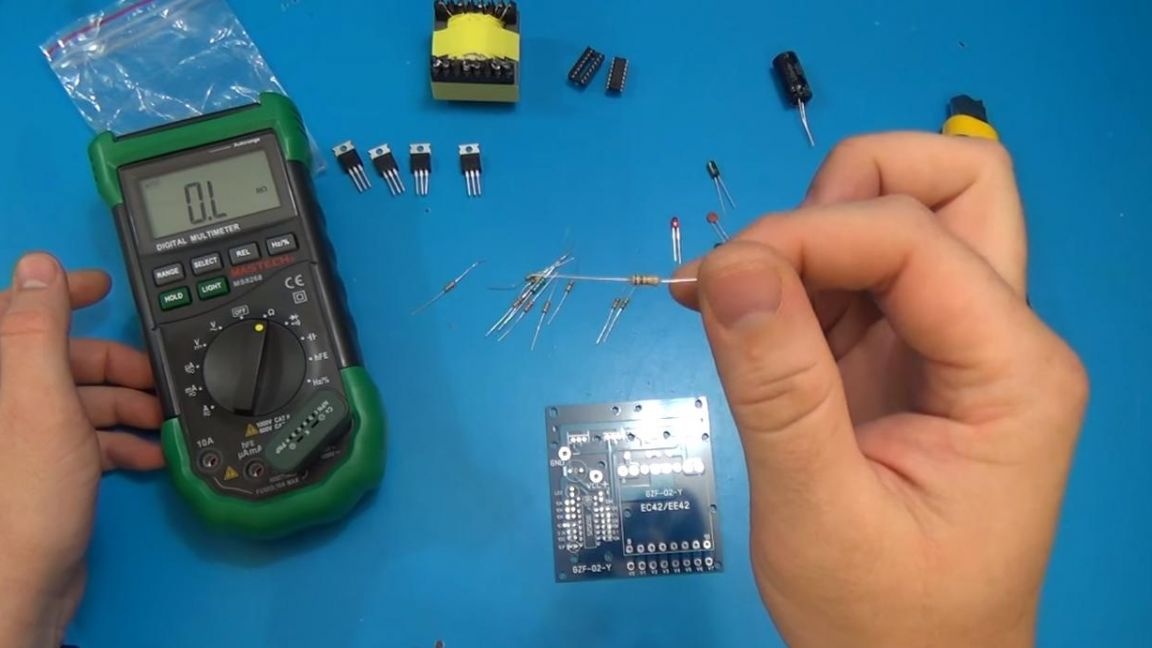
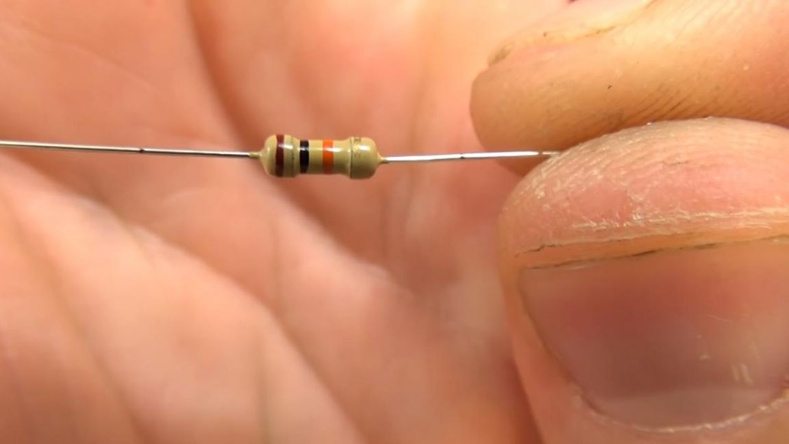
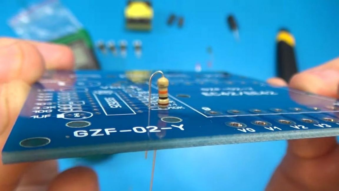
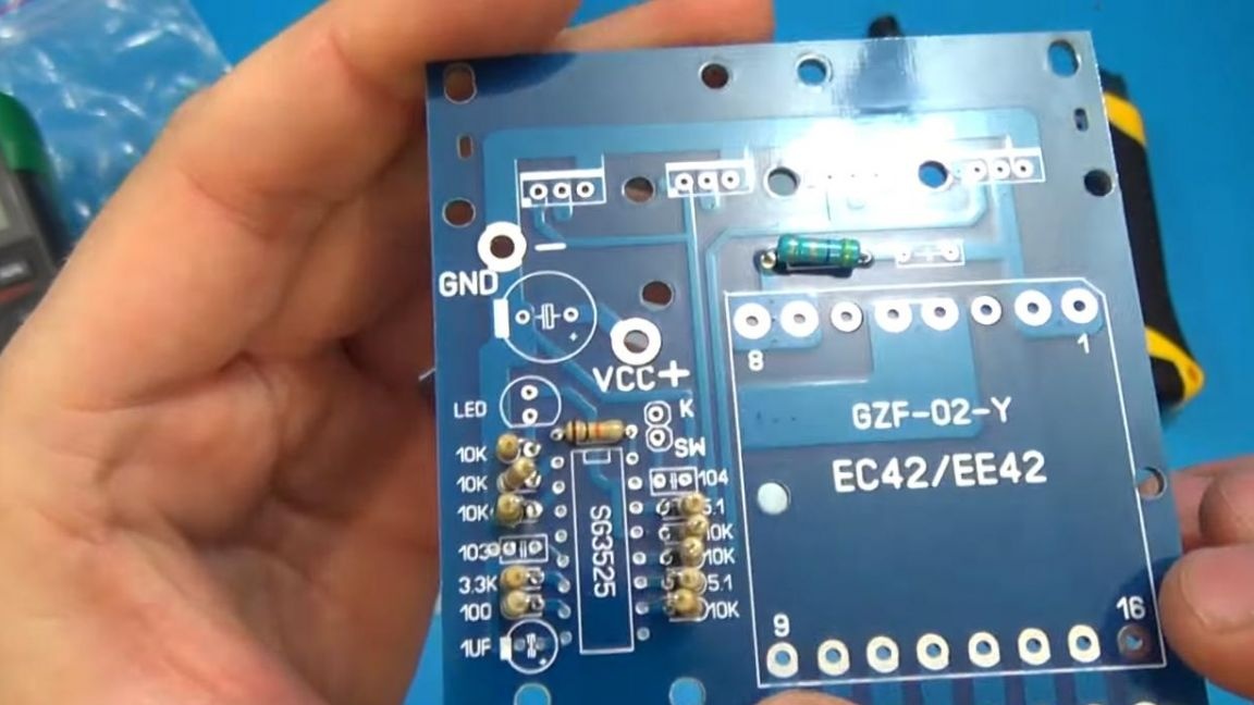
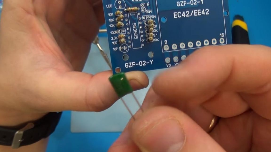
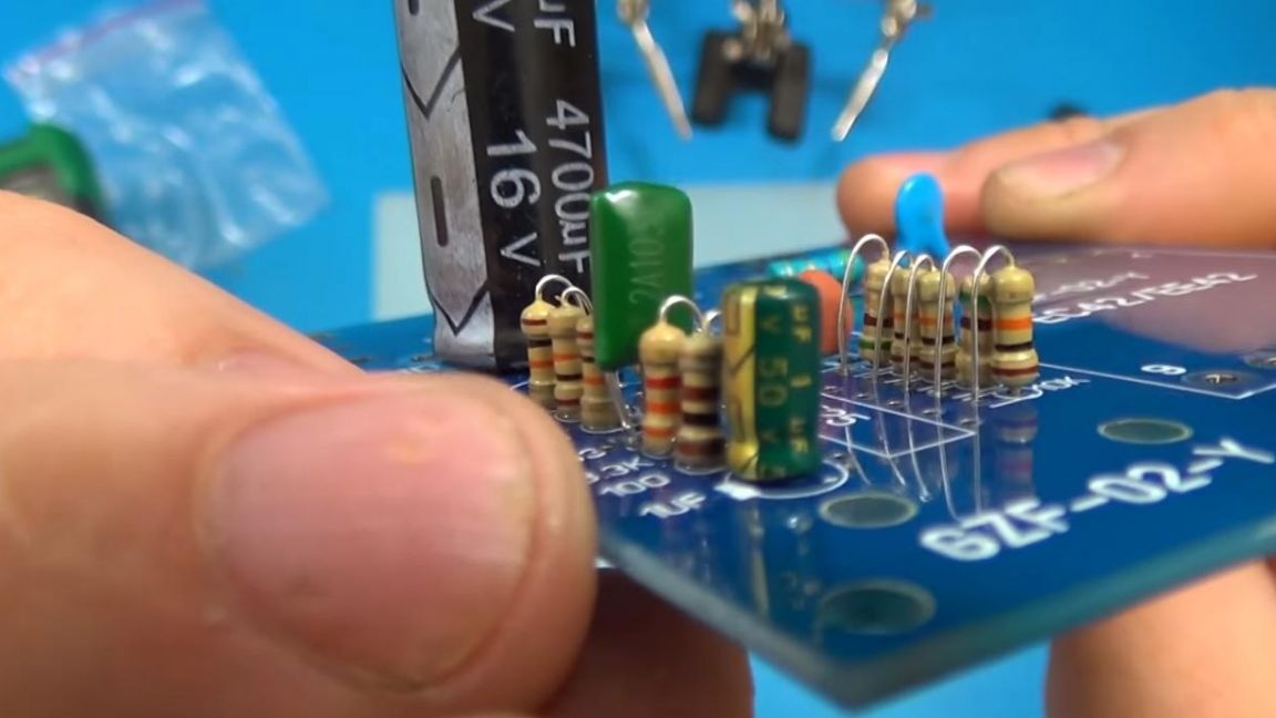
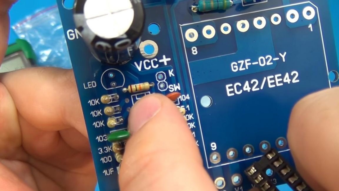
There are three ways to determine the value of resistors: using a multimeter, a look-up table and a resistance calculator. The first method will be the fastest, but if you do not have a multimeter, then you can also build a circuit without it. In this case, the resistors on the board will be located vertically, as in the photo, so one of the legs will need to be bent during installation.
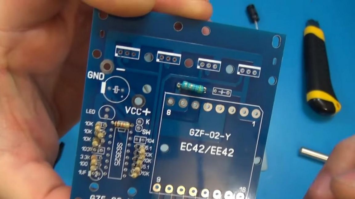
As a result, there should be 11 resistors, we solder them according to the rating and marking on the board itself.
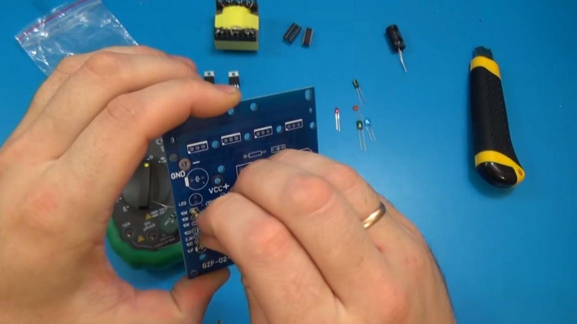
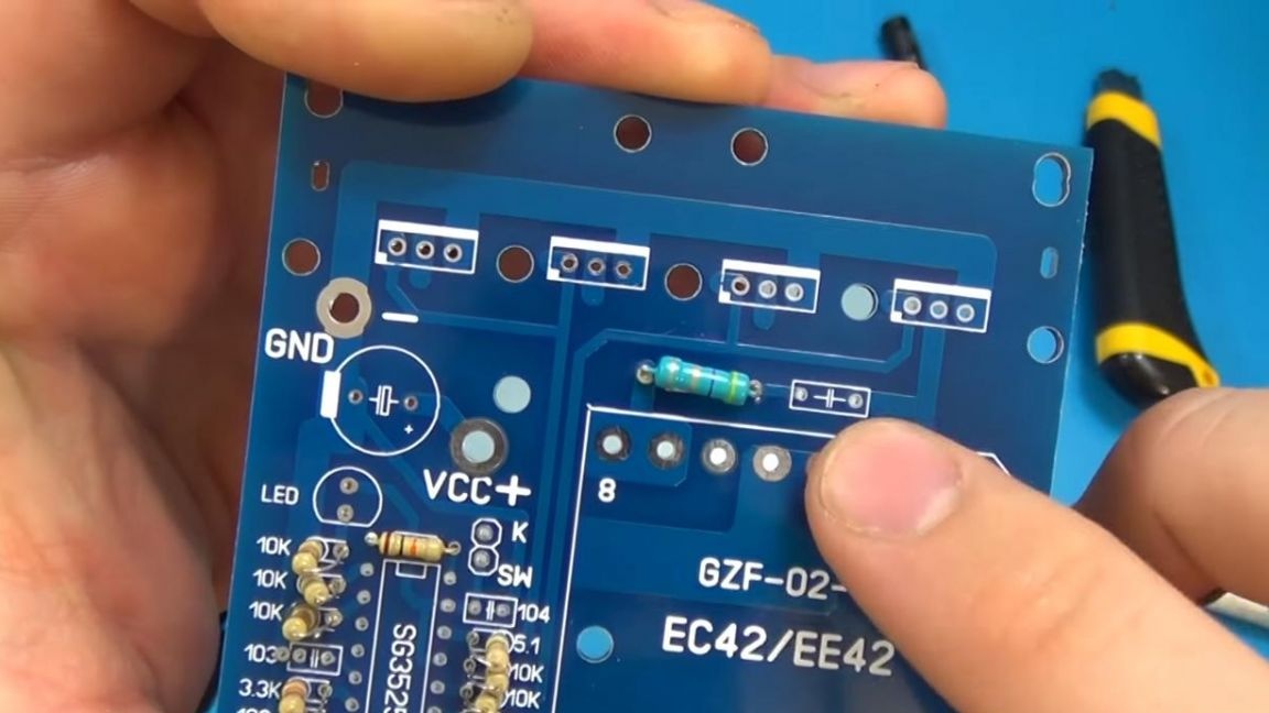
In an unsigned place, indicated by an empty rectangle on the board, we install a large resistor.
We solder the components to the board contacts, apply the flux in advance for better soldering.
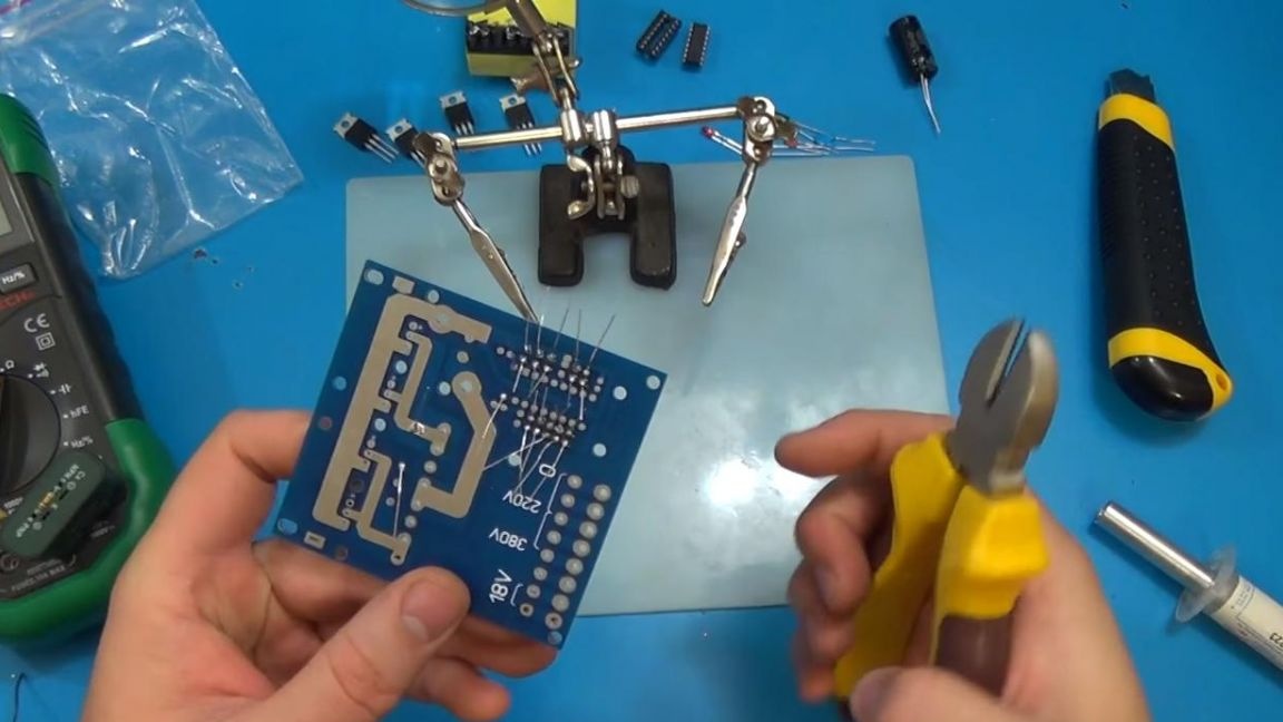
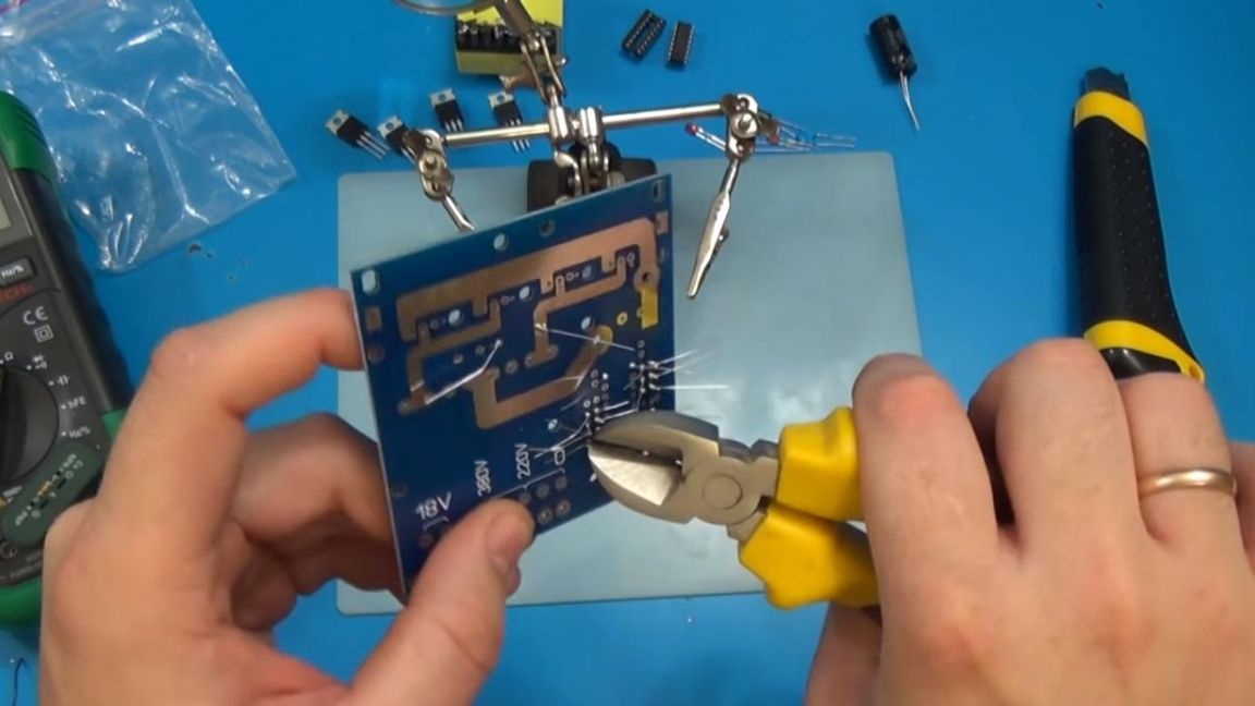
After that, with the help of side cutters, we remove the protruding legs of the radio components, while being careful, as you can easily tear out the circuit board.
Step Two
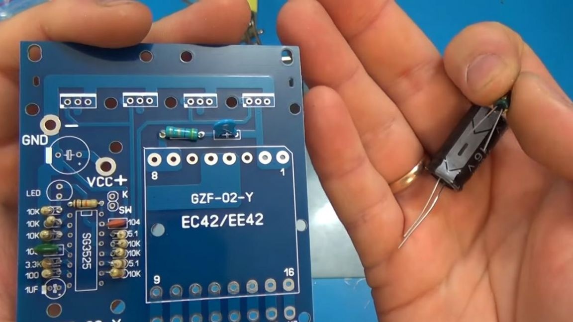
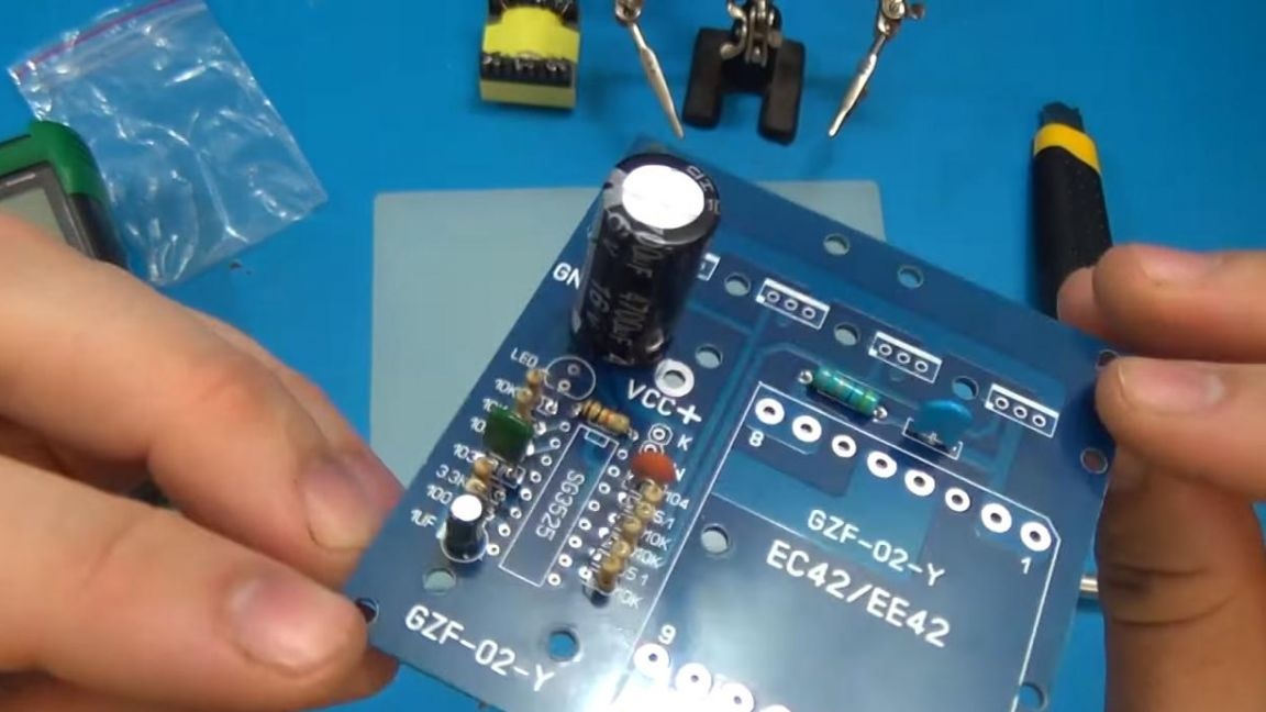
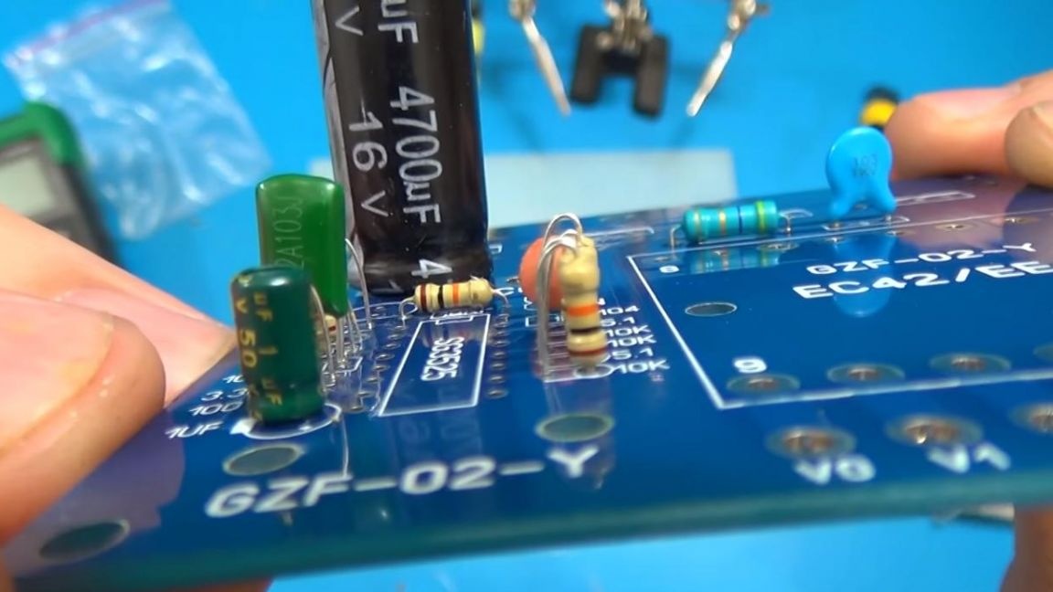
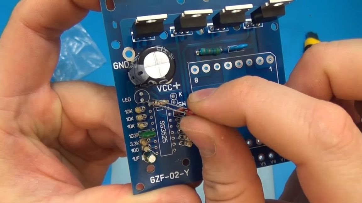
The installation of capacitors looks approximately the same, in this case it is important not to reverse the polarity of the electrolytic capacitors, the plus is shown on the board, and the negative output is indicated by a wide line.
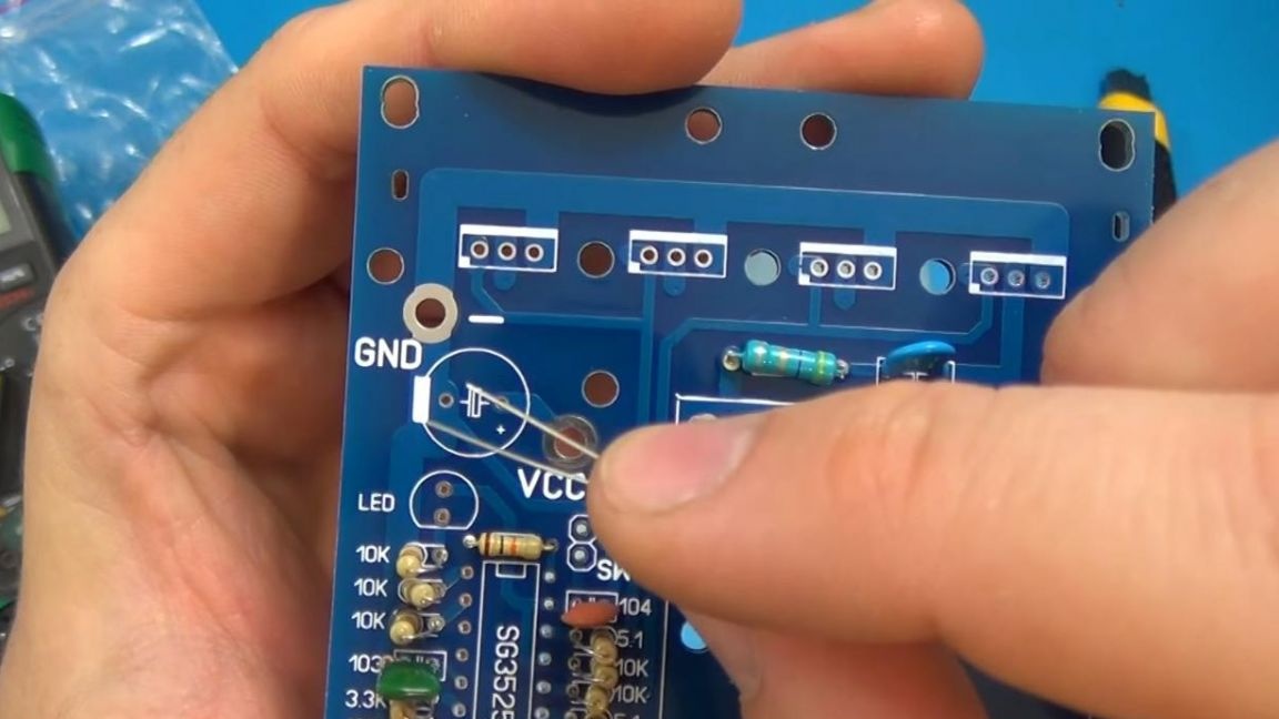
It will be difficult to confuse the capacity during their installation, since the size of the capacitor is 4700 microfarads much larger than that of a capacitor with a capacity of 1 microfarad.
Next, we install ceramic capacitors, they are shown on the board with numbers 104 and 103, the 103rd has a green color on the case, and we put a blue capacitor next to a large resistor.
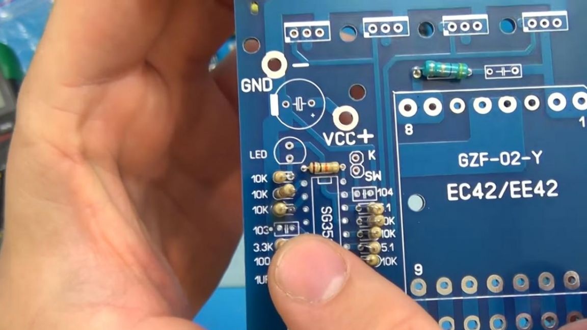
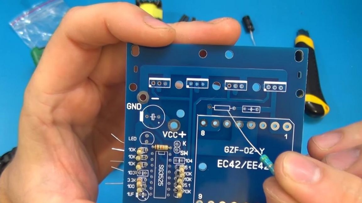
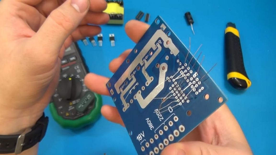
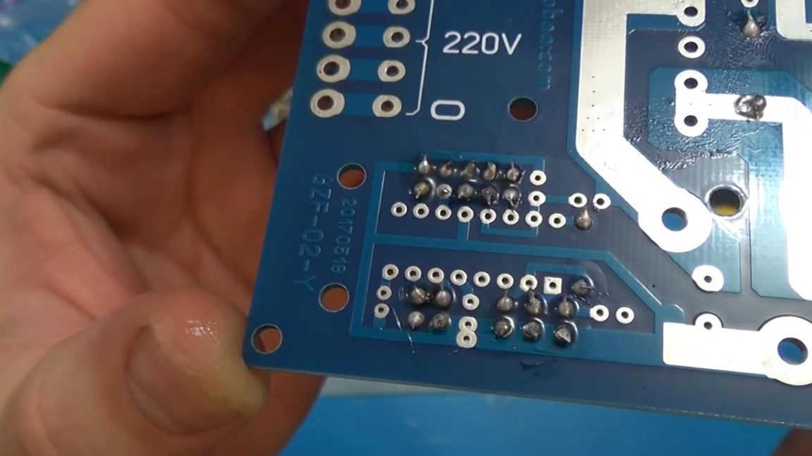
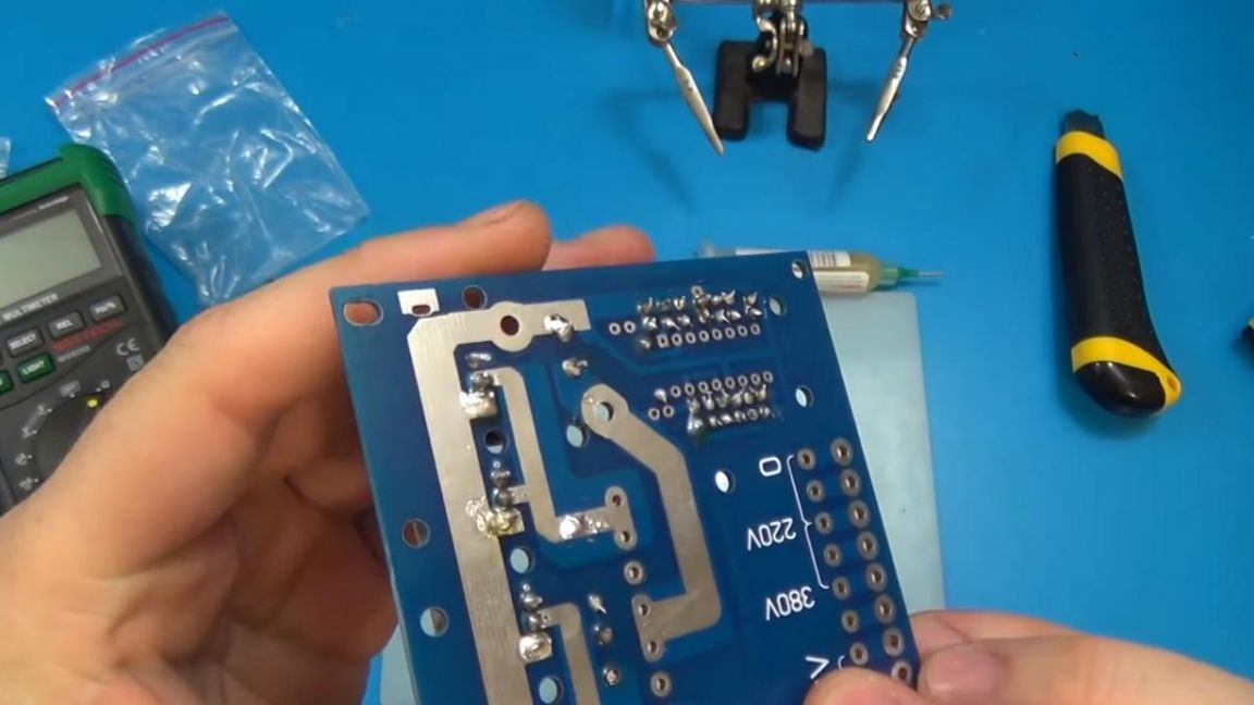
On the back of the board, solder the findings of previously installed components and remove excess legs.
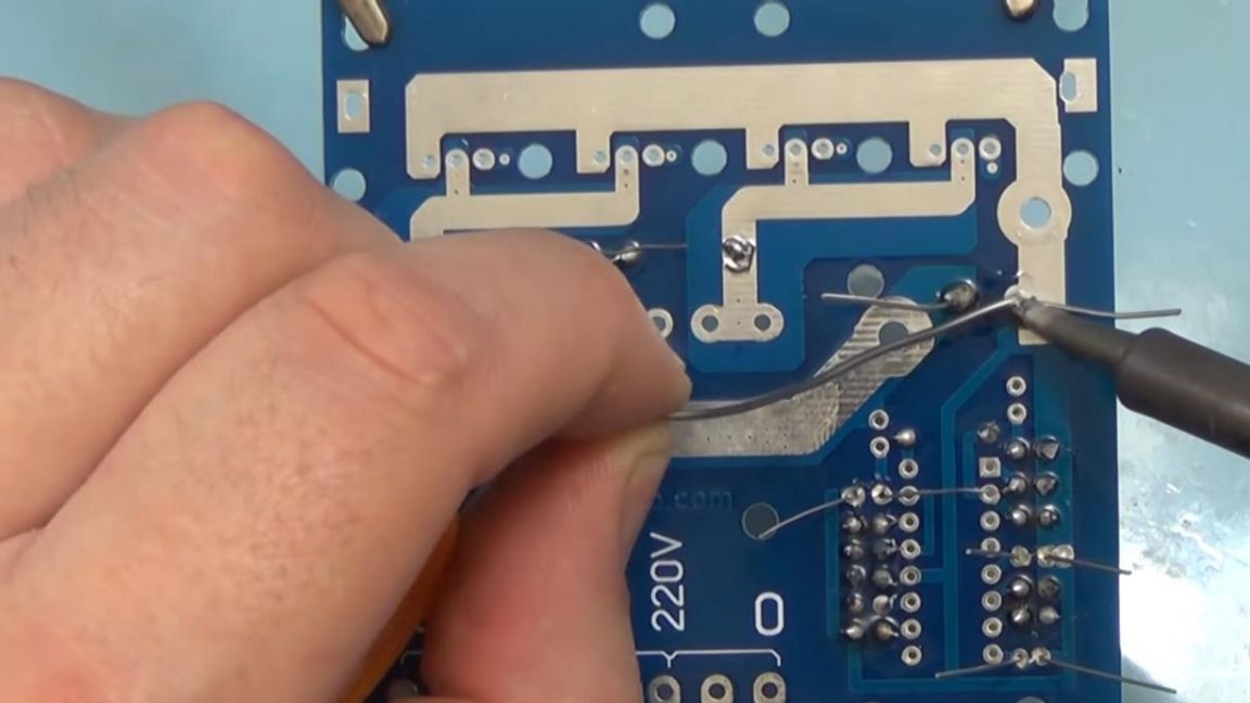
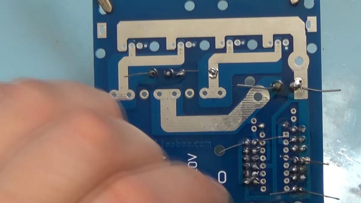
The result is something like this, for aesthetics, you can trim components.
Step Three
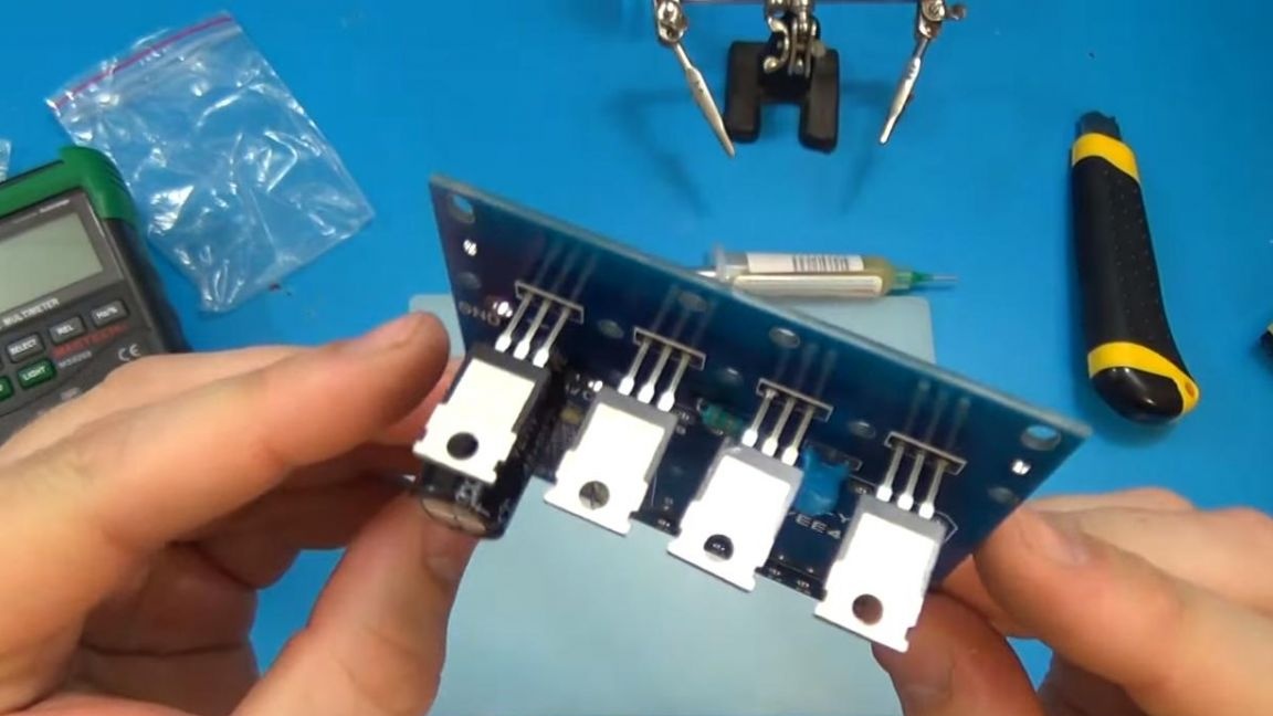
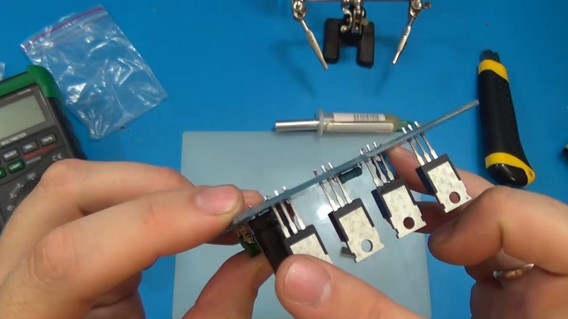
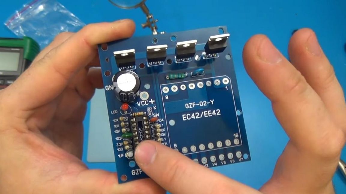
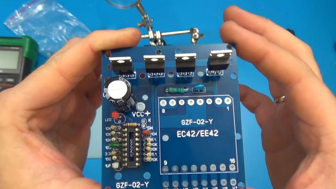
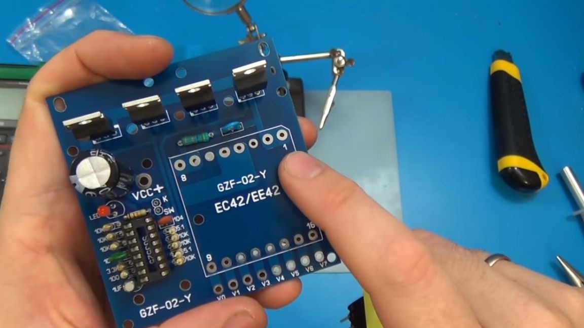
Now we solder the missing elements, namely four transistors, a DIP-socket for the microcircuit and an LED.
We solder the LED on the board with a long lead to the plus, short to minus, on this board the polarity is indicated by a slice, so there will be a minus contact at the place of the cut.
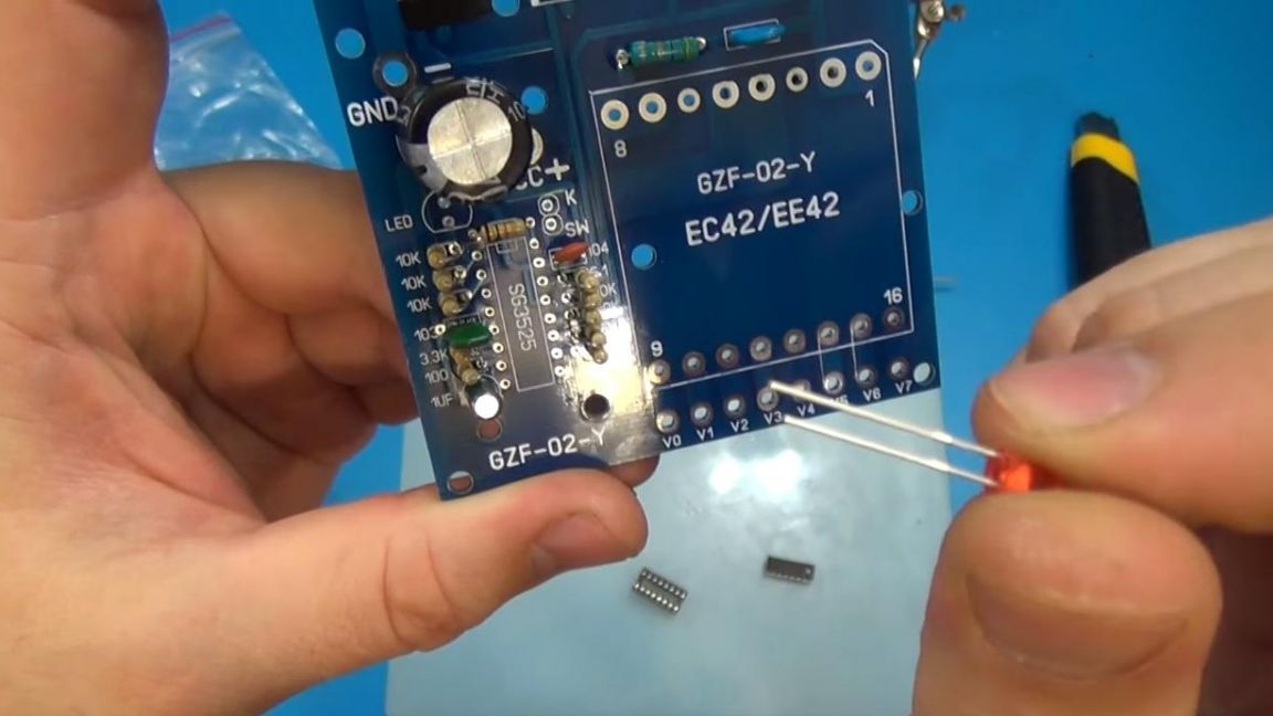
The panel for the chip has a key on top, which is both on the board and on the case itself.
Solder all components, also do not forget to use flux.
Step Four
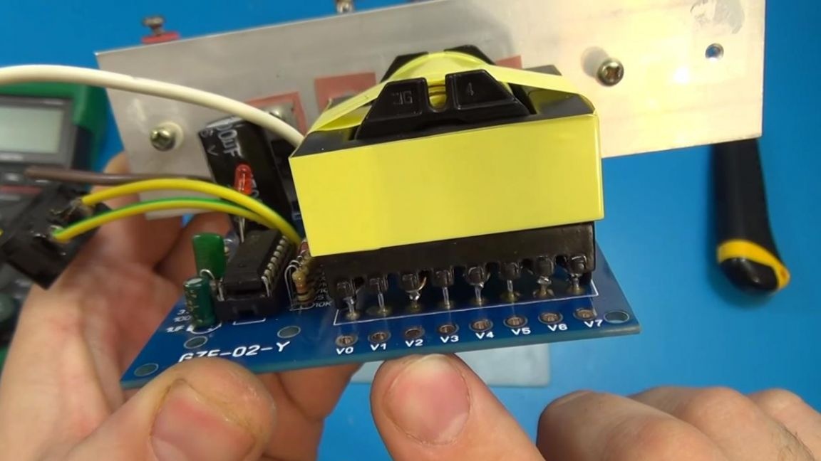
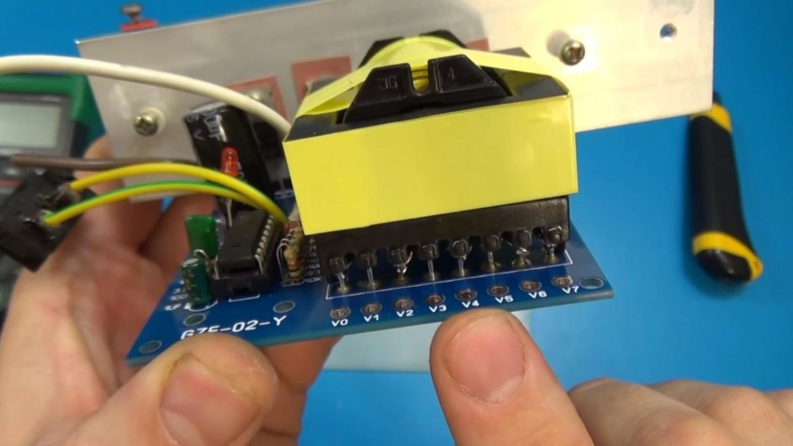
It's time to solder the largest part on the board, namely the transformer, its numbering of legs goes from right to left, we combine the point on its case with the reference point.
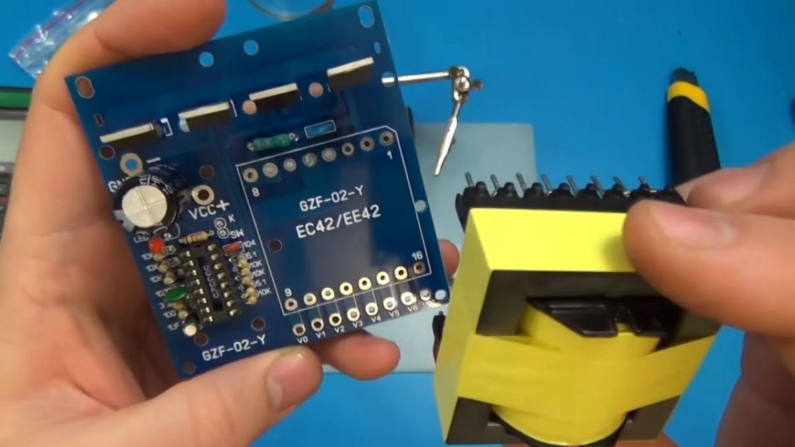
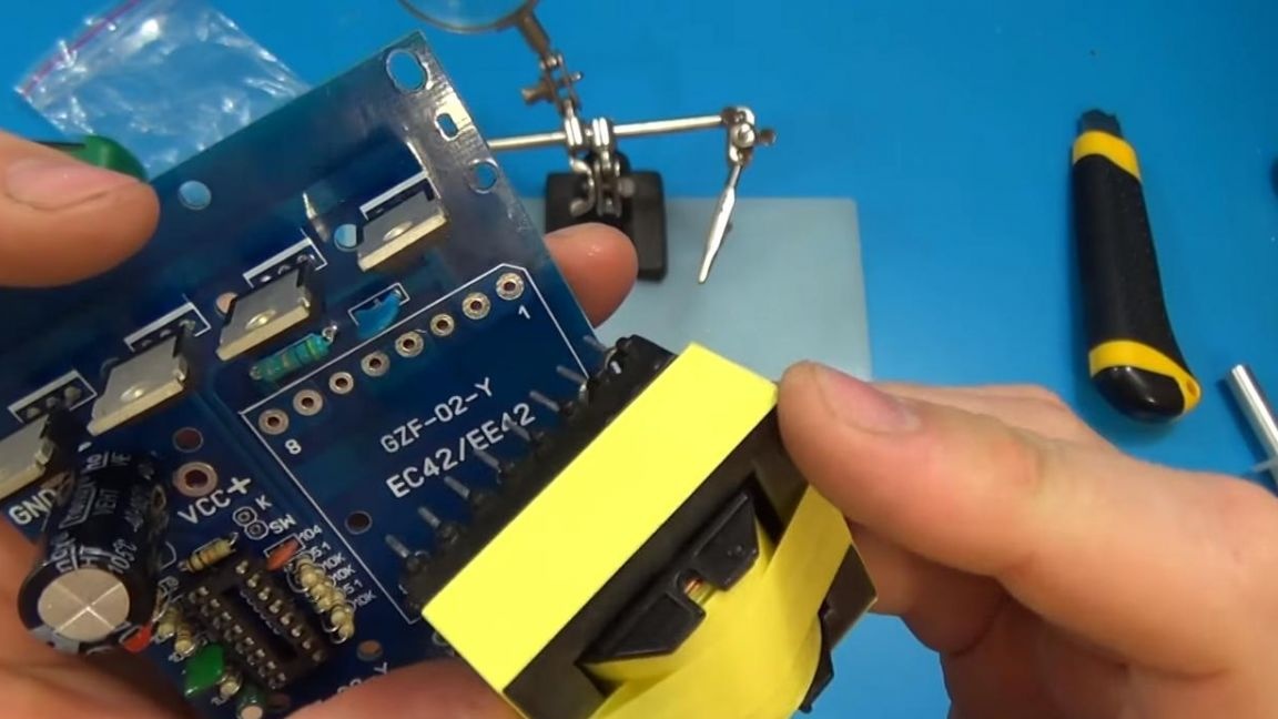
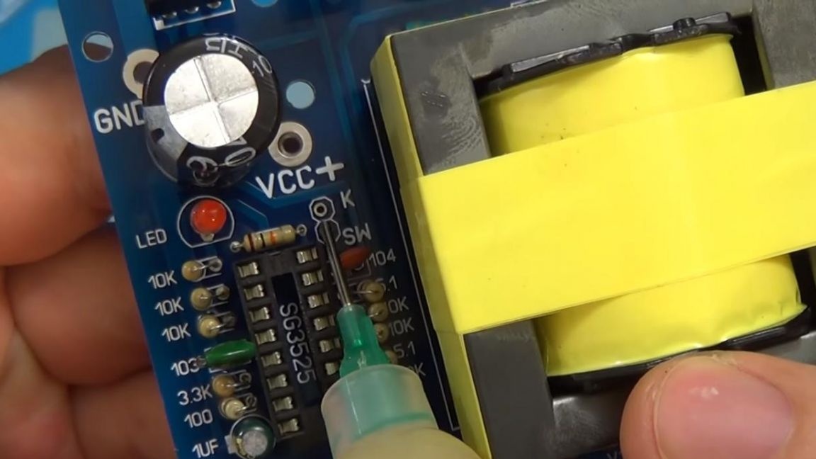
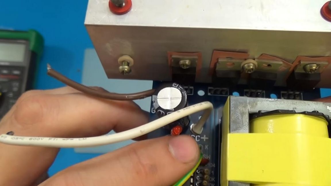
We solder the conclusions to the board, as well as two wires for the power button, which are connected to contacts K and SW.
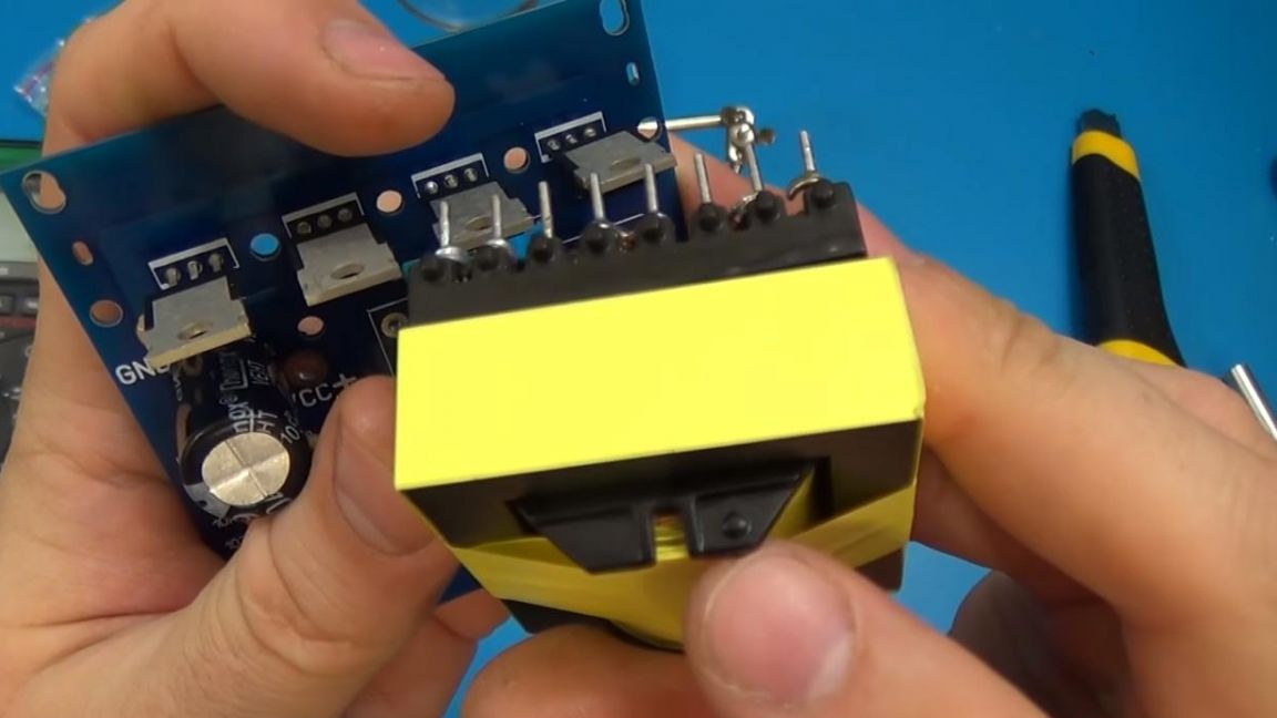
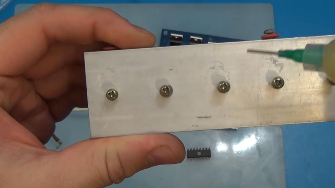
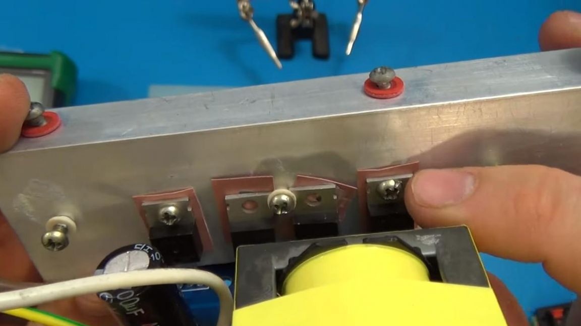
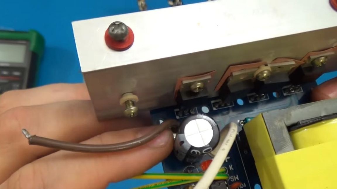
It remains to install the radiator on the transistors, so as not to overheat them and not disable the board. Each transistor must be isolated and not shorted to the other.
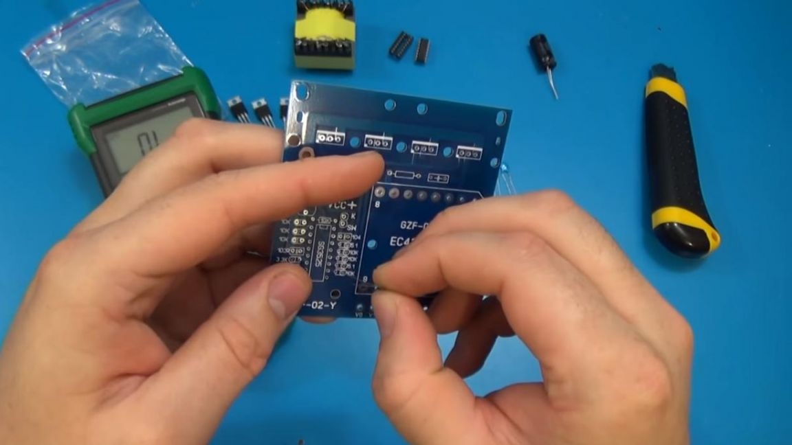
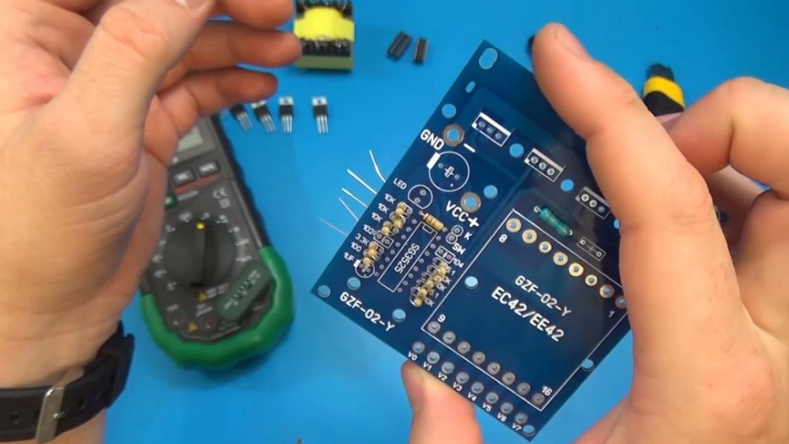
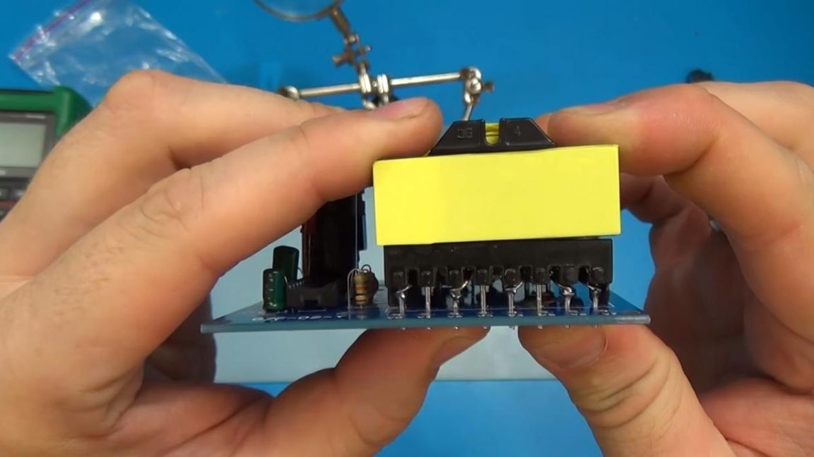
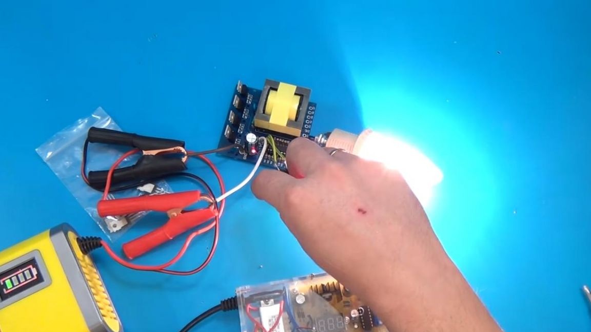
Now you can check this inverter, in the VCC + wires we connect the positive wire of the power supply, and to the GND negative.
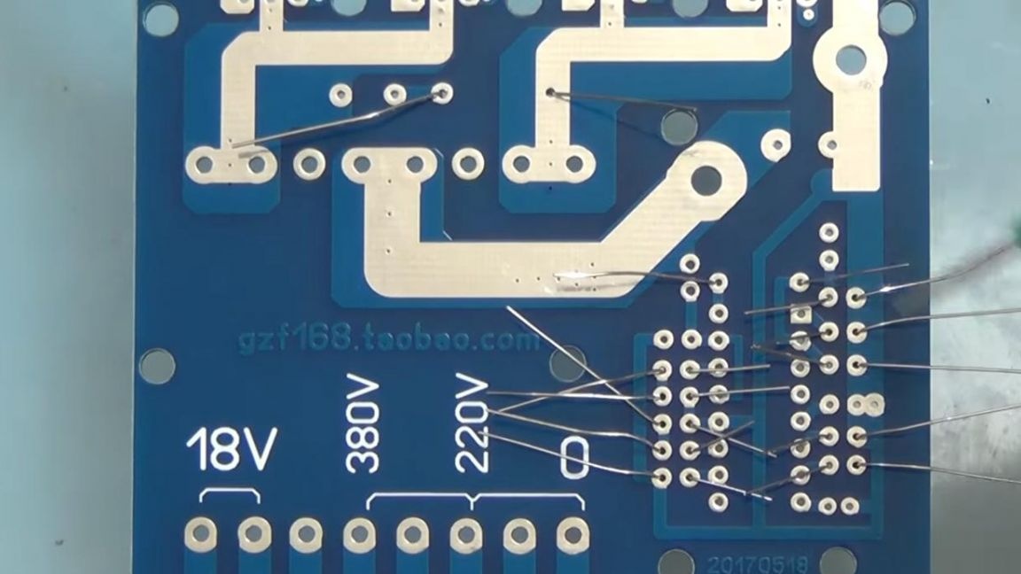
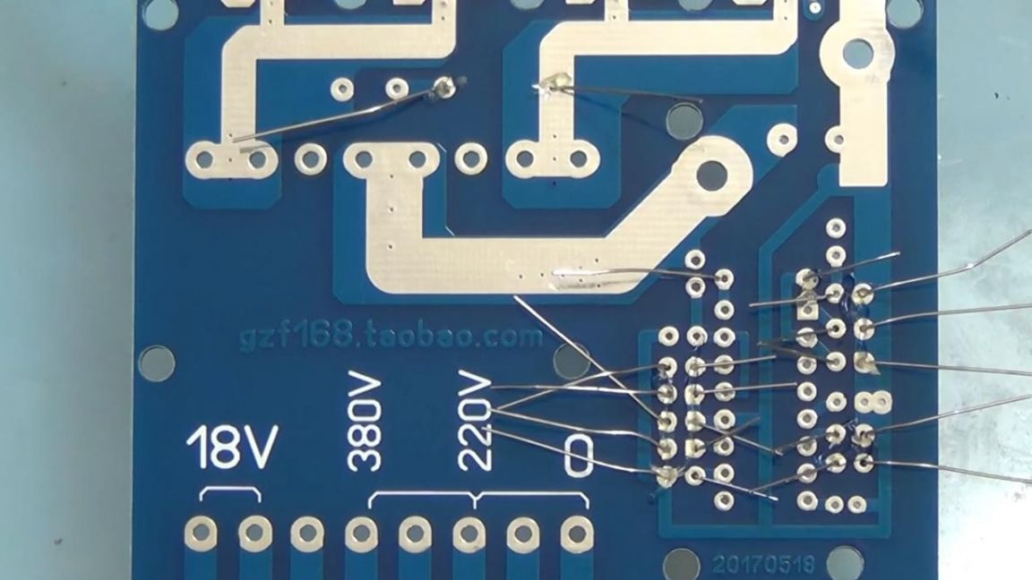
The output of the transformer V0 is minus 220V, V2 is + 220V and V4 380 volts, respectively. V6, V7 are the conclusions of the 18 volt AC line.
On a simple household light, we check the inverter’s performance, the light is on, which means the inverter is fully operational.

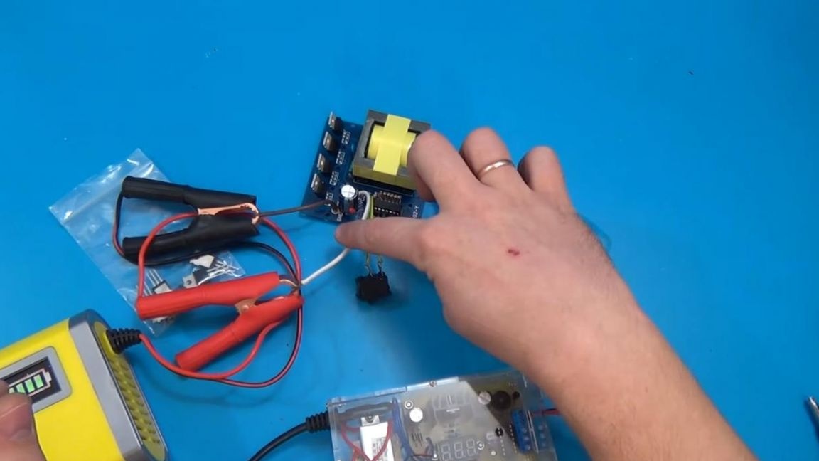
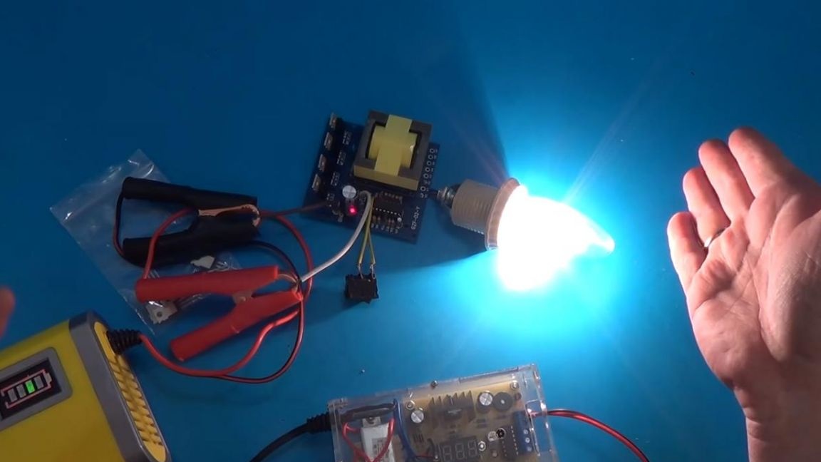
In this inverter, the maximum declared power is 500 watts, which is most likely a marketing move, in any case, it will be enough to power low-power elements requiring a voltage of 220 or 380 volts.
That's all for me, all with high-quality kit-sets and new creative ideas.