
Hi the inhabitants of our site! In this article, we will assemble another Chinese whale kit. Namely, we will assemble a radio with an alarm clock and a display. The assembly is quite simple and everyone will assemble it. Having assembled this designer, you will gain not only assembly and soldering experience, but also, you will also have a new radio receiver with a display that can be used in the country or in the garage.
This kit kit can be ordered from the Chinese, namely on the aliexpress website by clicking on this one.
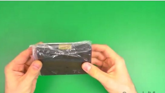
The kit kit itself is supplied in a bubble bag, in which there is a plastic case itself inside of which all the components for assembly are located.
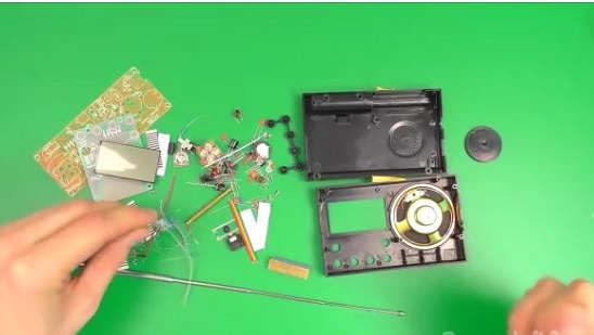
The kit includes:
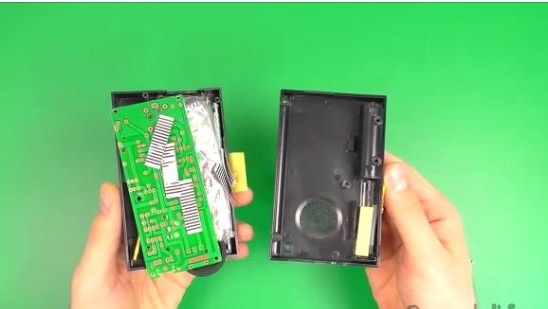
1- Plastic case.
2- Not very detailed instructions and diagram.
3- Three scarves with contacts.
4- Two printed circuit boards.
5- Package with a huge number of radio components.
6- Antenna.
7- Speaker.
Well, let's not waste time and get down to assembling this Chinese kit kit.
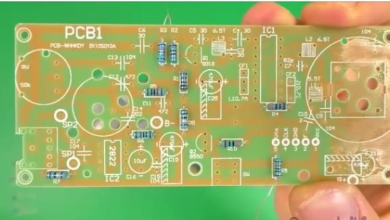
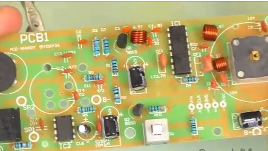
1- First, let's assemble a large printed circuit board. And let's start with resistors. We measure the values of the resistors and insert them in their places. Places are indicated on the circuit board. If you don’t have the opportunity to measure the values of resistors, then you have the opportunity to find them through a mobile application, just in the search engine of the mobile application store you enter “learn the name of the resistors”. The application translates the colors applied to the resistors in their values.
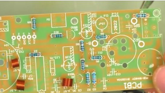
2- This is how it should look like, a printed circuit board with resistors installed in it. The set will still have six resistors of different colors and ratings.
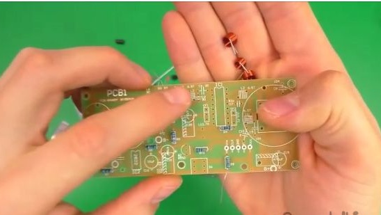
3- After which we take and insert the inductors into the printed circuit board. There are three inductors in the set, two large and one small. On the printed circuit board there are two 6.5 marks and one 5.5 mark, respectively, we solder the large ones where 6.5 is, and the small one where 5.5.
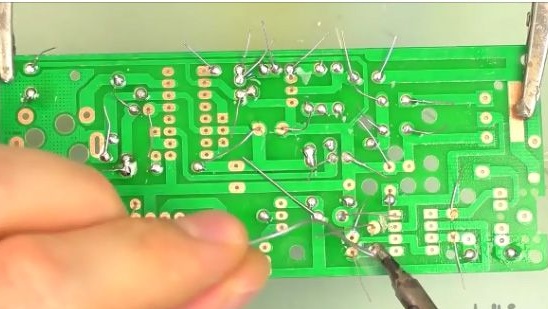
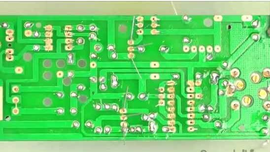
4- After installing the inductors and resistors, we can solder them. We will solder after lubricating them with flux.
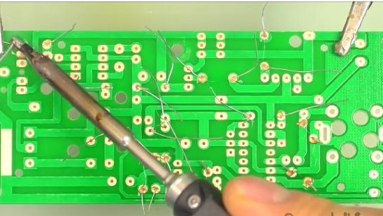
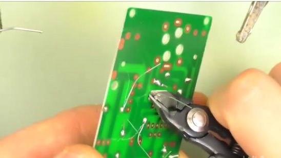
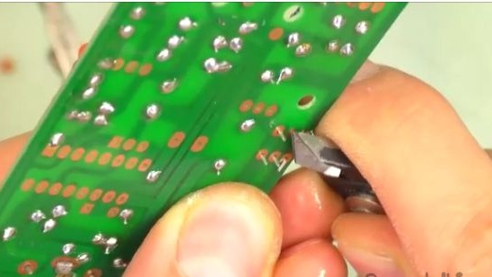
5- After being soldered, we bite off the extra contacts.
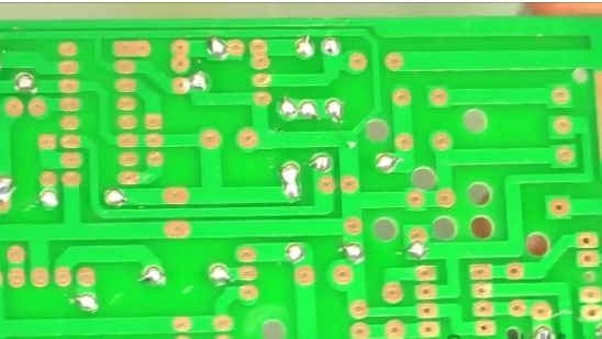
6- At the moment, the printed circuit board of the radio should look exactly the same as in the photo.
7- After which we install the capacitors polar and non-polar. Everything is signed on the printed circuit board, and it will be very difficult to get confused, even if for the first time you assemble such kind of designers. Even if you have difficulty in notation, you can see the legend on the Internet.
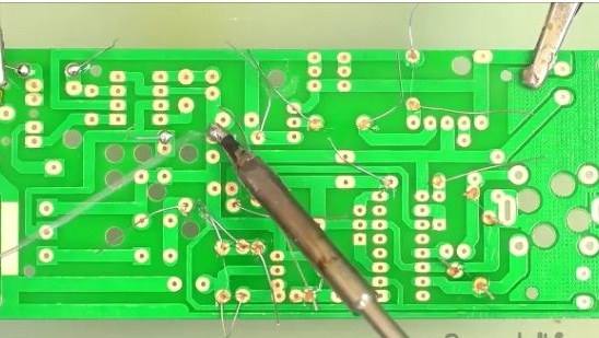
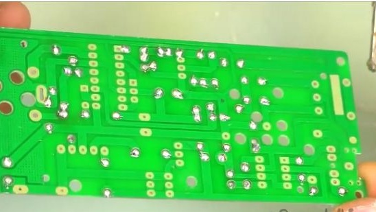
8- After installing the capacitors on the printed circuit board, solder them.
9- And again, cut all the conclusions.
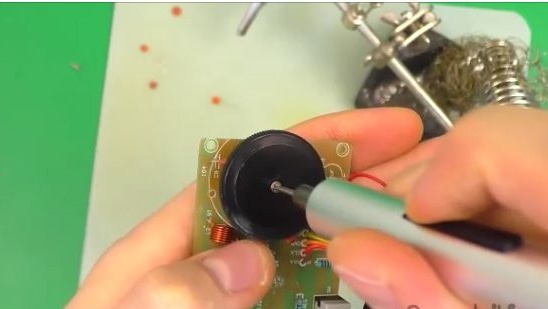
10- After which we install a variable resistor to adjust the volume of the radio.
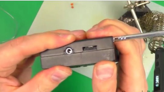
11- Then the jack for connecting a mini jack to 3.5 mm.
12- Next, install a variable capacitor.
13- After we inserted a capacitor of variable capacity on the printed circuit board, we will fit its legs so that it does not fall out.
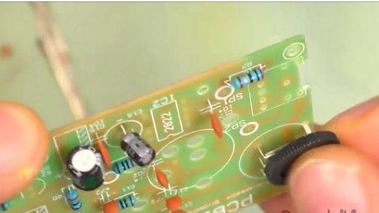
14- This is what your printed circuit board should look like at the moment.
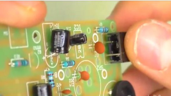
15- After which we install the micro switch.
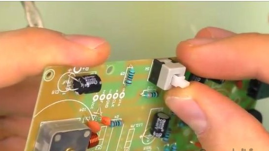
16- Unbend the legs of the micro switch in different directions so that they do not close and the micro switch does not fall out during soldering.
17- Next, install two transistors and two microcircuits on a printed circuit board. Also, there is nothing complicated in this, since everything is very correctly marked on the printed circuit board. Do not forget that microcircuits should be installed by keys.
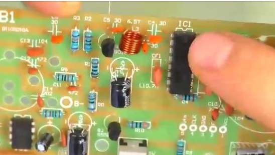
18- And we install quartz filters, and this is also nothing complicated.
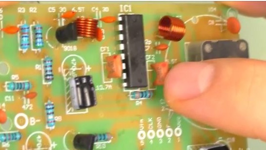
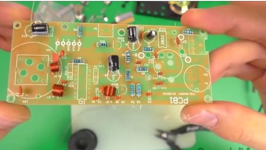
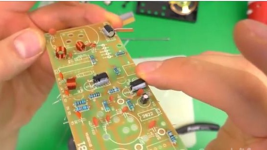
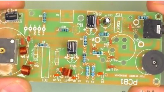
19- After we installed all the elements on the printed circuit board, it should look something like the one shown in the photo below.
20- And solder all newly installed elements to the circuit board.
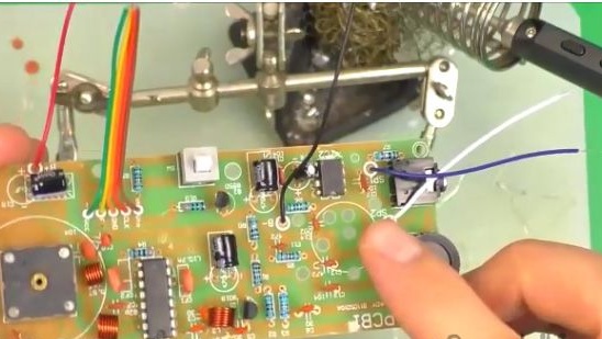
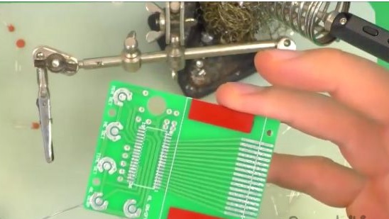
21- After all the elements have been soldered onto the printed circuit board, solder the wires to it. Speakers one, two are the findings on the speaker. B- and B + are the findings on the power of the circuit board. And the five-wire loop contacts will go to the next board.
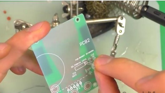
22- Then we take the second printed circuit board and we will work with it.
23- We insert quartz into the board.
24- Three capacitors that are signed on a printed circuit board.
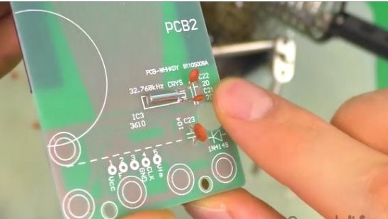
25- Install the diode by connecting the stripes on the board and the element.
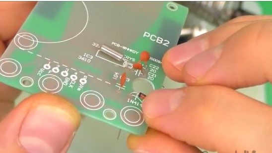
26- After you have installed all the above said elements, solder them and cut off the excess conclusions.
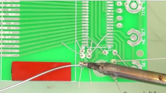
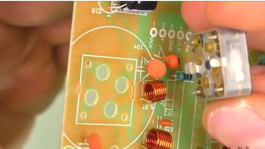
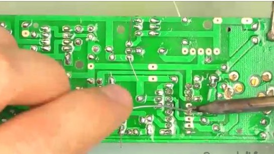
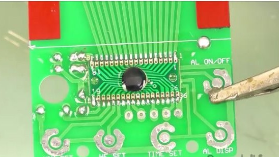
27- Then we solder to the taken board, the board with the chip having connected their numbers on both sides.
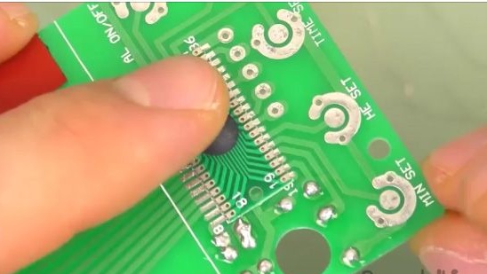
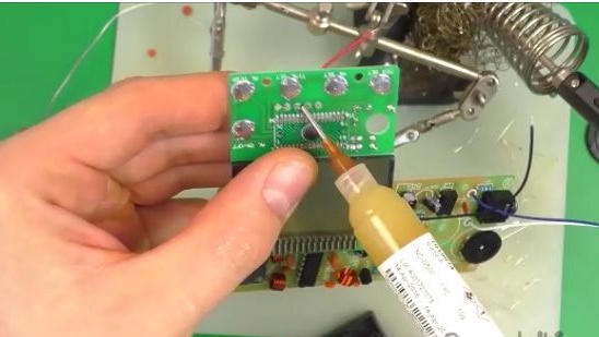
28- We apply flux on the boards on both sides.
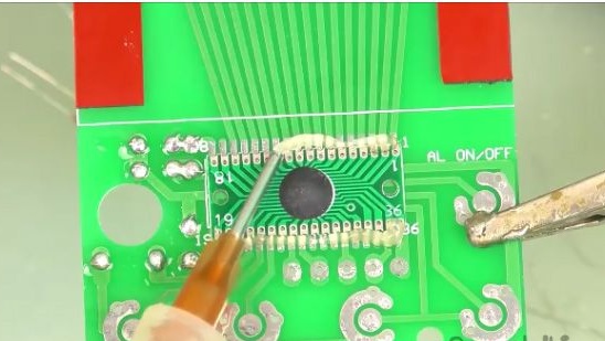
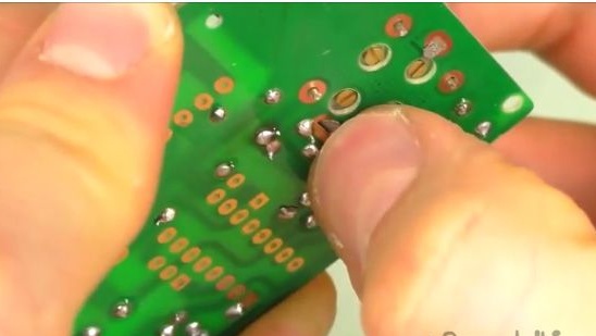
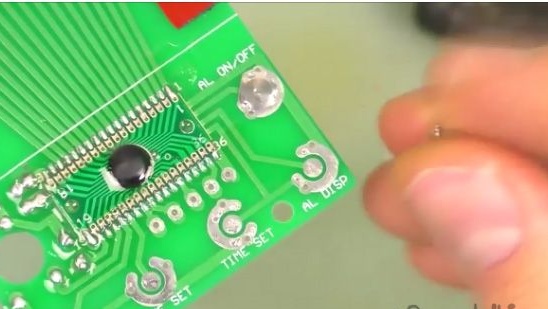
29- First we grab on the sides.
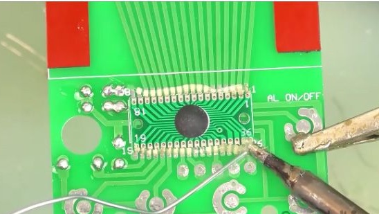
30- And then we solder all the other conclusions.
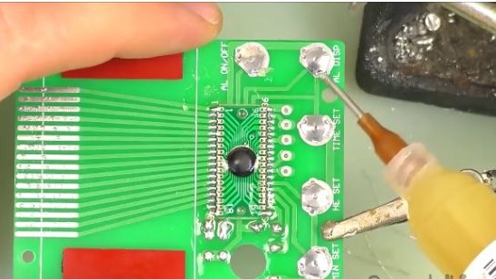
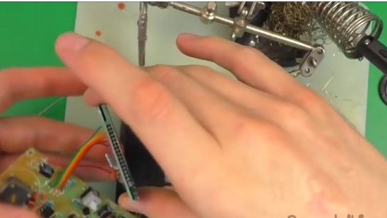
31- And then it will be necessary to solder not large metal plates, they are buttons, to the printed circuit board.
32- Insert these plates into the grooves and gently flux them and solder them.
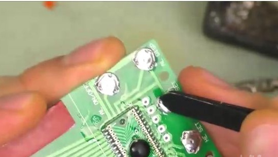
33- We need to test their performance by simply clicking on them, we should hear characteristic clicks.
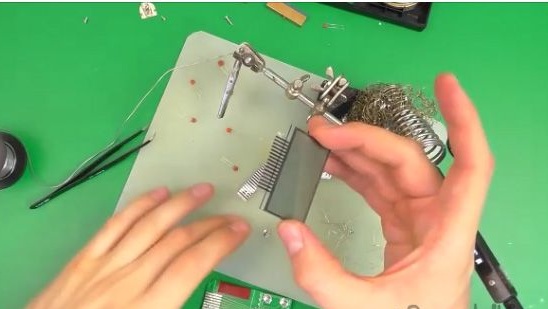
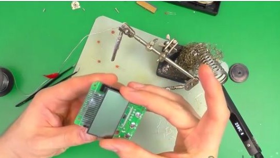
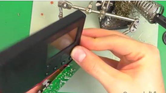
34- Next, we take the display and in the light should see translucent contacts. We must stick them with those plates that come with the kit.
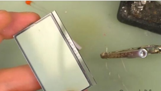
35- Something like this should look like a display with contacts glued to it (see photo below).
36- From the board with which we recently worked, we peel off the strips of double adhesive tape.
[center]
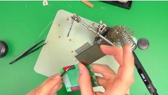
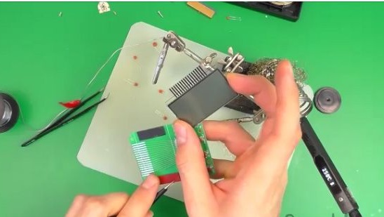
37- And we glue the display to the printed circuit board, so that the contact tracks on the printed circuit board converge with the contact tracks on the display.
38- Now we glue the tracks by pressing on them with some flat object. Contacts must match
but not a big error is permissible.
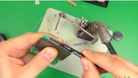
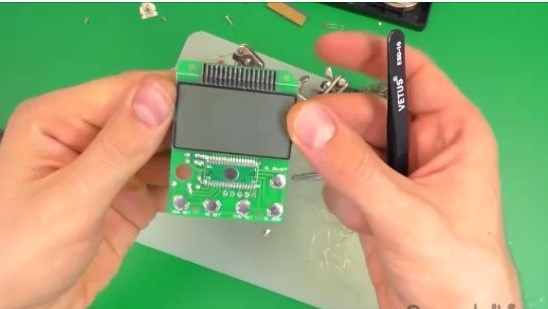
39- This is how the display glued to the printed circuit board should look like (see photo below).
40- Now we need to solder the two printed circuit boards, soldering the cable together.
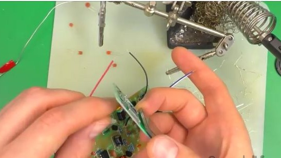
41- Flux conclusions on the other hand and solder.
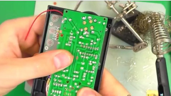
42- After the two printed circuit boards are soldered together, they will need to be installed in the case.
43- First, insert the small board and fasten it.
44- We check the operability of the buttons, by clicking on them, we should hear characteristic clicks.
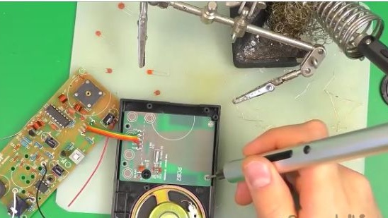
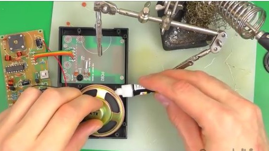
45- Now solder the wires to the speaker.
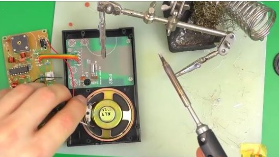
46- In order for the speaker not to fall out and to sit firmly in place, grab it with superglue.
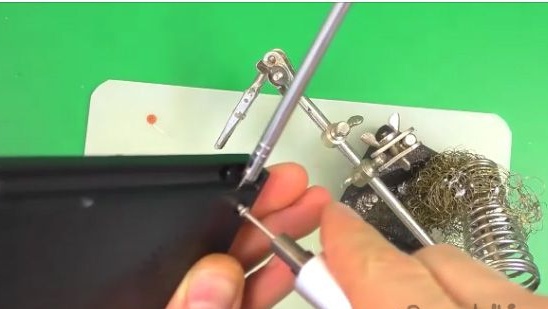
47- Fasten the adjustment knob with a small screw.
48- And now we fasten the printed circuit board itself to the case.
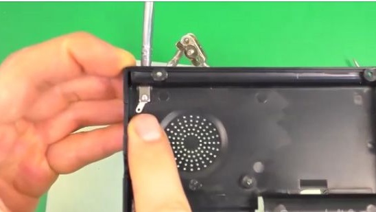
49- We screw the antenna to another part of the body.
50- And on the other hand, do not forget to make contact, that in the photo you will need to solder the wire to it.
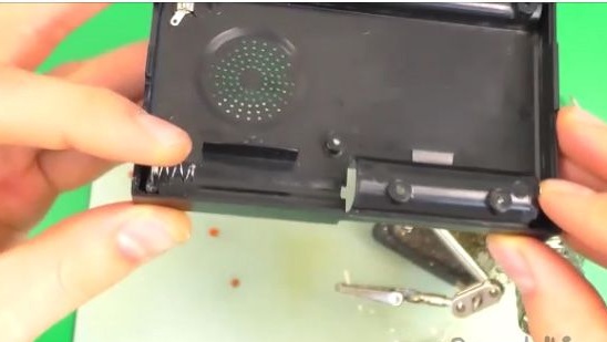
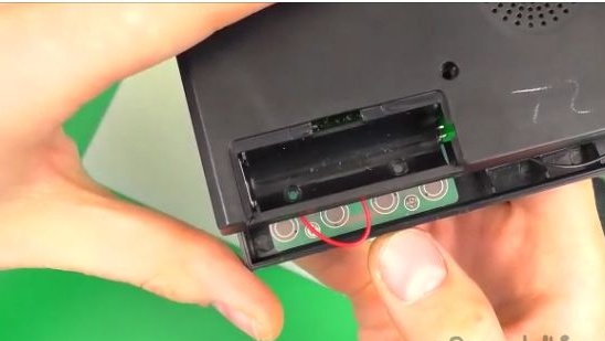
51- Also do not forget to set the contacts for the batteries.
52- And solder the two sides of the housing with wires.
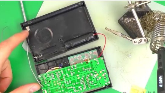
53- It remains to connect both parts of the housing, connecting them together and push until it clicks.
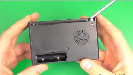
54- The screws that we screwed into the bottom board will have to be unscrewed and screwed on top.
55- Twist all the other screws.
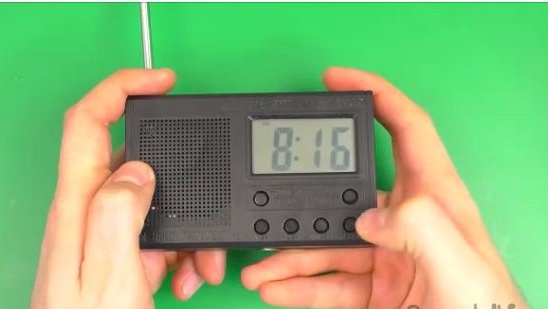
56- But that’s it! Now it remains to insert the batteries into it and see if it works or not.
The coolest thing about assembling such kits is at the end to try whether it works or not.
We insert batteries into the receiver and see what works! Now you have an excellent radio for your summer cottage or for your country toilet, which you built yourself. I hope that this article was useful for you, and it will be useful to you when assembling this radio receiver. You also have a wonderful opportunity to watch the video assembly of this radio with a display, as well as its configuration.