
Hello friends! In this article I will try to describe and show the assembly of the next kit kit from China, namely a multimeter. Having collected this kit kit, you will get not only an invaluable soldering experience, but also a multimeter very needed in the household. Of course, its accuracy will be inferior to expensive store multimeters. But for ordinary household needs it will be more than enough. This kit kit can be purchased by clicking on this one.
Included in the kit.
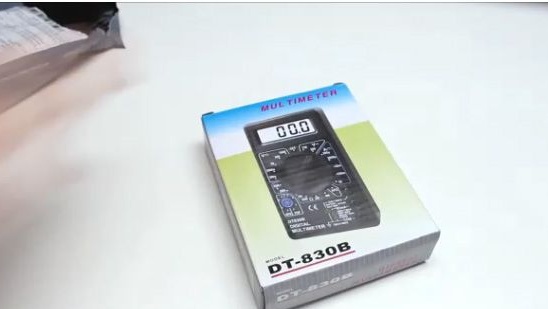
1- Box with a set.
2- Plastic case.
3- Probes.
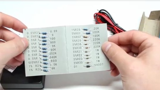
4- A set of resistors with their ratings.
5- The instruction is completely in Chinese.
6- Scheme of the multimeter.
7- Battery.
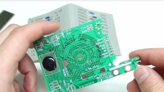
8- Printed circuit board.
9- A bag with different elements.
10- Display.
11- Sticker on the multimeter.
Let's build this kit kit
1- In order to assemble this kit, we should first purchase it. After we purchased it, we see that it is unusual for the Chinese to pack it in their own box.
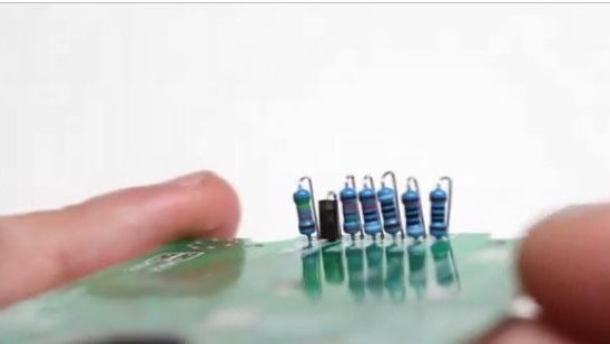
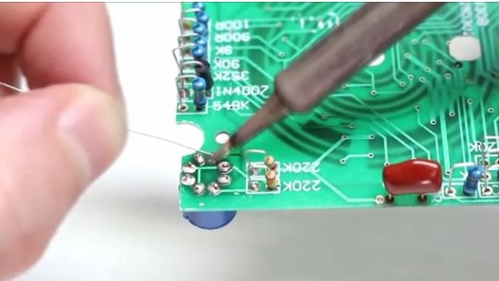
2- First, take a printed circuit board and install resistors on it. The values of all resistors are written on the cardboard on which they are located and supplied. Resistors should be installed vertically, since the holes for the legs are very close to each other.
3- Something like this should be located one part of the resistors on the printed circuit board (see photo below).
4- Solder newly installed elements to the circuit board.
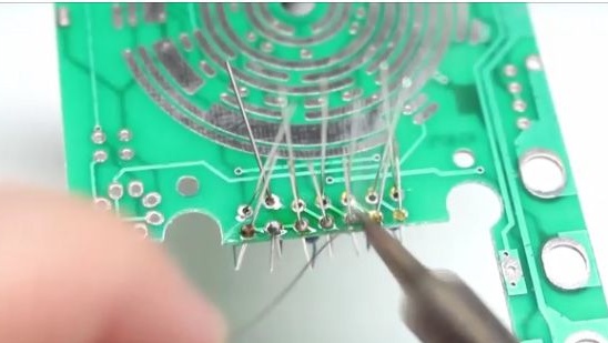
5- After soldering one part of the resistors, insert the other part of the resistors.
6- And just solder the second part of the resistors to the printed circuit board.
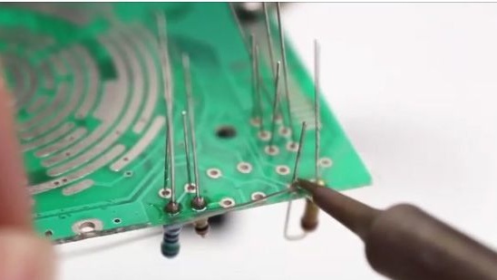
7- Something like this should look like a printed circuit board with resistors installed on it.
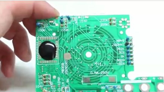
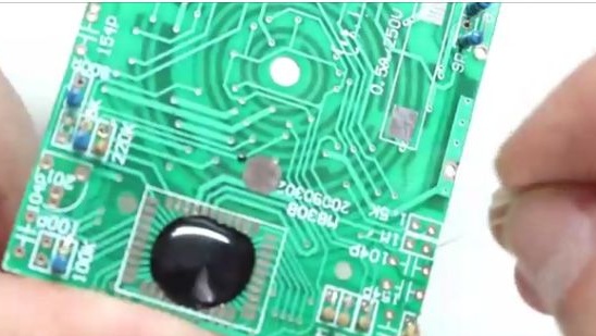
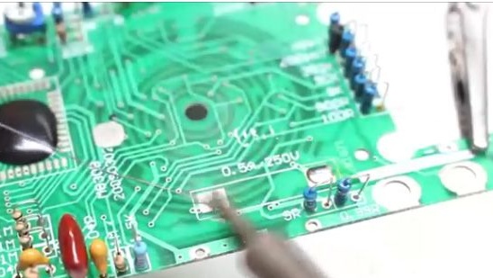
8- In the indicated places (see photo below), we install three capacitors from the bag.
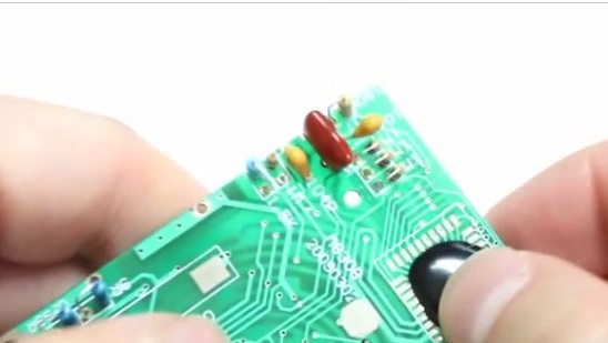
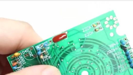
9- After which we install an adjustable resistor on the circuit board.
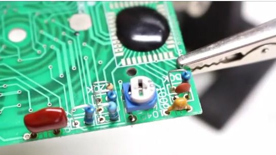
10- And solder all the elements just installed on the circuit board.
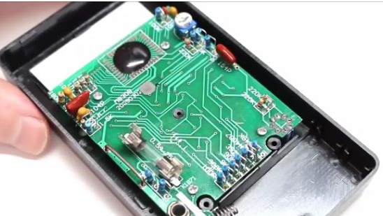
11- This is how the printed circuit board should look like at this stage (see photo below).
12- After which we see, in the lower part of the printed circuit board there are two small squares with contacts, they will need to be applied with a flux
13- After we applied the flux to these places, they will need to be tinned with solder.
14- After which we need staples for the fuse, they will need to be soldered to tinned places.
We put them on the right place on the printed circuit board and apply a soldering iron. The brackets will need to be soldered in parallel to each other.
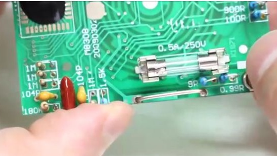
15- This is how the fuse clips should look after they are installed on the circuit board (see photo below).
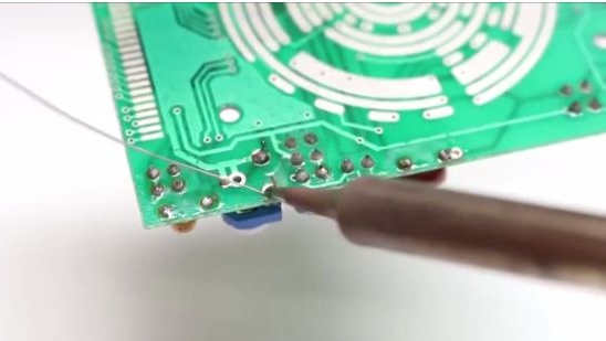
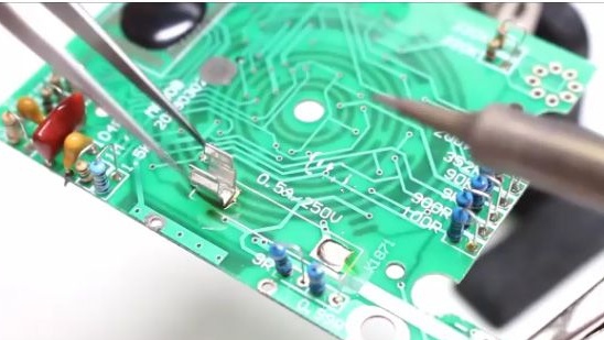
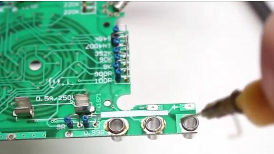
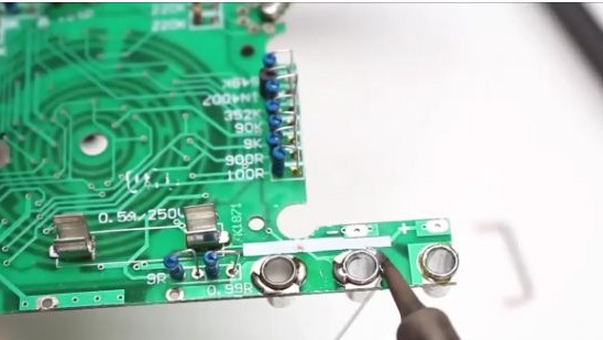
16- Next, install the connectors for the probes on the printed circuit board.
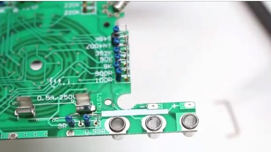
17- We apply the flux to the place of soldering of the connectors for the probes and the printed circuit board and solder them.
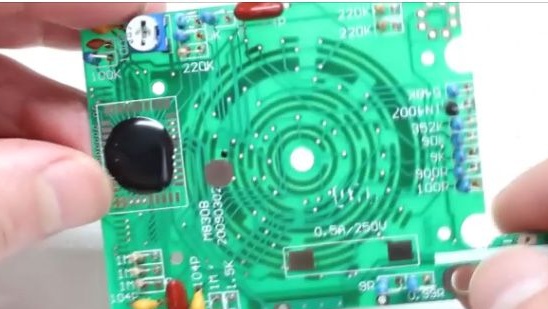
18- After which we install and solder “noise” onto the printed circuit board.
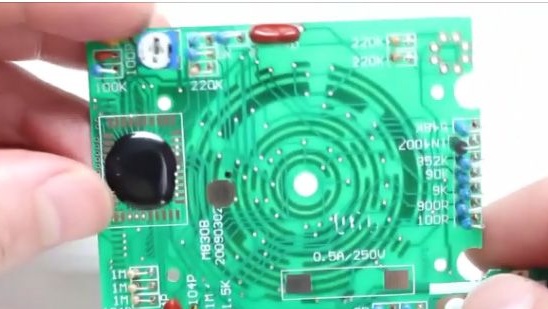
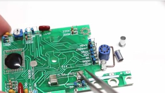
19- Next, we will need to install a block for transistors. But before installing the pads on the circuit board
You will need to install the circuit board in the multimeter housing. The thing is that there is a guide in the case and there is a chance to install it incorrectly.
20- Only after installing the printed circuit board in the housing of the multimeter. We’ll install a block through the case (see photo below).
21- Then we pull out the printed circuit board from the case with the block.
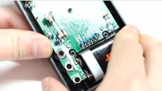
22- After which we solder the newly installed block for transistors to the printed circuit board itself.
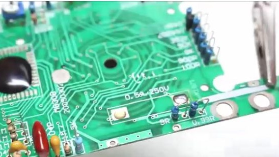
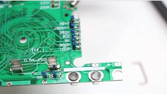
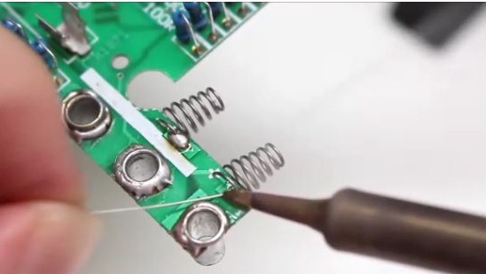
23- Next, install the springs from the kit onto the printed circuit board. These are contacts for a krone battery.
24- And we solder these contacts to the printed circuit board before that, not forgetting to smear the soldering spot with flux.
25- After which we install the fuse in the connectors that we previously soldered, you need to insert until
characteristic click.
26- This is how the fuse should be installed in its place (see photo below).
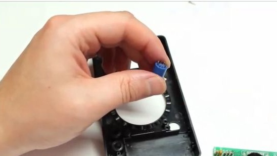
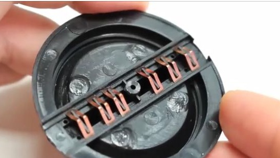
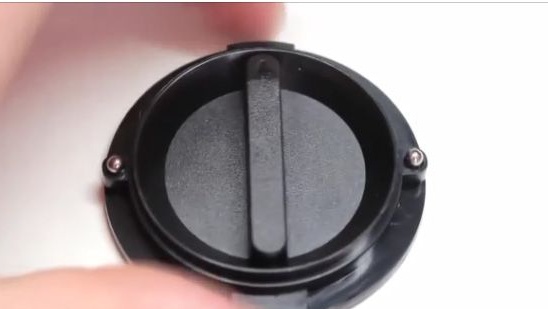
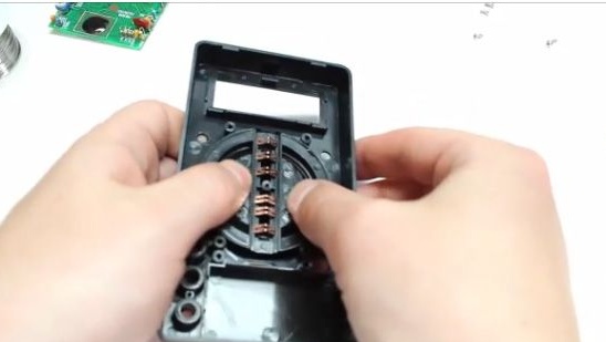
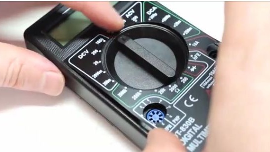
27- Next, we will need to assemble a twist with the help of which we will choose the operating modes of our multimeter.
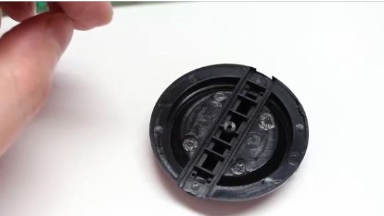
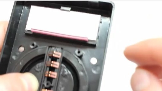
28- On this twist, we will need to establish copper contacts.
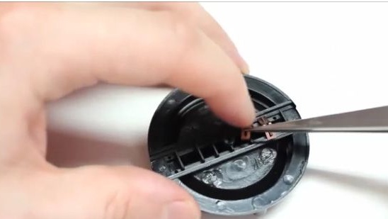
29- This is how it should look like (see photo below).
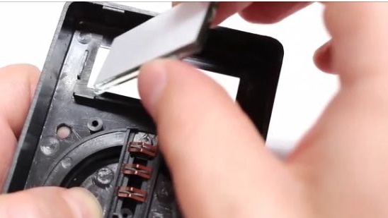
30- After which we turn the switch over, and on the other hand we will need to holes in the sides
install springs and balls.
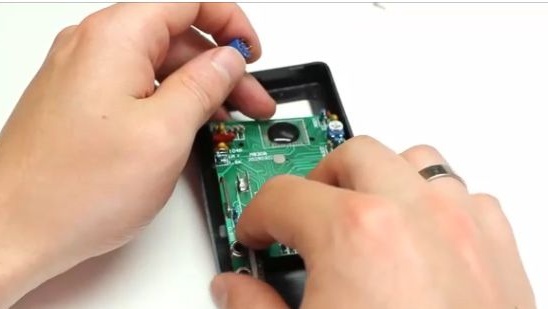
31- Next, put the switch on some flat surface.
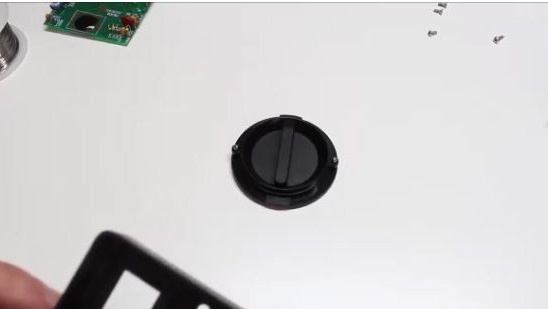
32- Carefully apply the multimeter to the switch (see photo below).
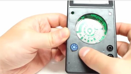
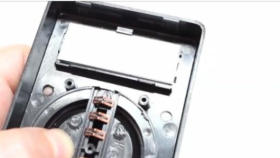
33- After which we will need to raise the switch, but this will need to be done very carefully,
so that the balls that are on the switch do not fall.
34- And turn the case over while holding the switch.
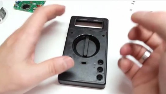
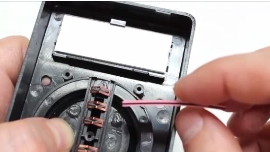
35- After which it will be necessary to install a display in the case, having previously removed the protective film from it.
36- We apply a conductive strip to the display of the multimeter, as this is shown in the photo below.
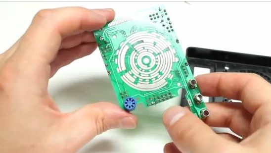
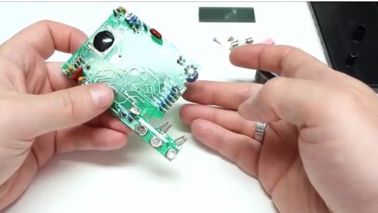
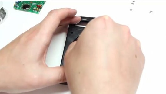
37- Then with one hand we hold the case of the multimeter on weight, and with the other we apply a printed circuit board to the case.
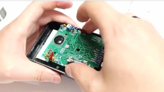
38- You should succeed, as it is shown in the photo below.
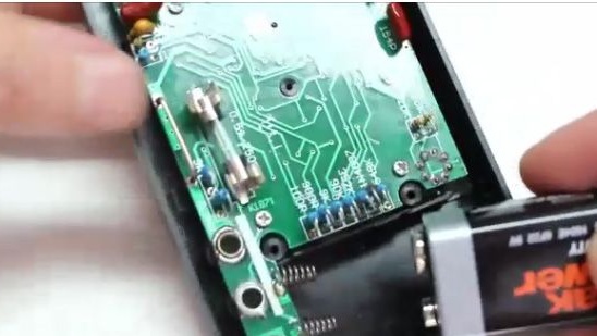
39- Install the battery of the crown format, which is in the kit. The contact farthest from us on the printed circuit board is minus, and the near contact is plus.
40- Close the housing cover and tighten the screws.
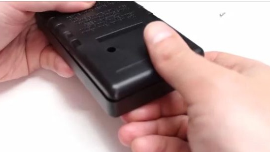
41- Then we paste a beautiful sticker with scales.
42- Done.
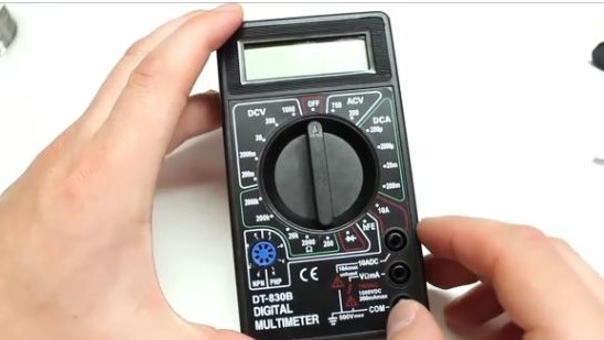
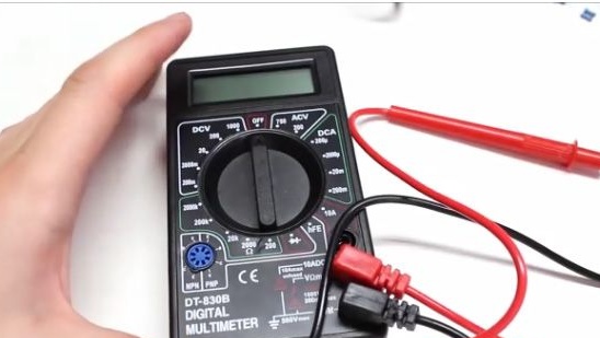
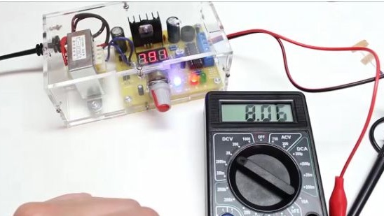
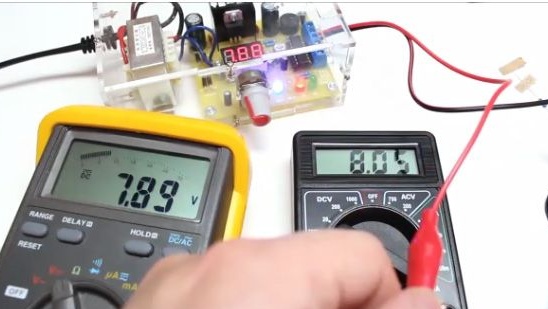
We check the newly assembled multimeter by connecting to it a power supply and another better multimeter, we see that there is an error, but it is not large. For the economy will go, twelve volts from twenty four you can accurately distinguish.

Well, that’s all, thanks for your attention. I hope this article will help you in the assembly of this multimeter. You also have a great opportunity to watch the video assembly of this kit kit.