

What do we know from the history of the crown? The compasses we have known since school serve to draw perfectly regular circles. The history of this tool has more than one thousand years, as far as one can judge by the perfectly accurate circles that archaeological scientists see on the surfaces of ancient structures. When excavating the mounds of ancient Gauls, in France, an ordinary compass made of iron was found. And during the excavations of Pompeii, scientists were surprised to find a slightly different tool, it was about the same purpose, but very, very complicated in structure.
As it turned out, it has not changed much since the time of the Roman Empire, in the same form it is produced and used in the modern world, although now there is even a digital caliper. This term of foreign origin consists of the German word "krone" - a crown and the Latin "circulus" - a circle. Belongs to the category of drawing and measuring instruments. It has two legs, most often, arcuate in shape, between which you can set the desired angle using a micrometer screw, which is also included in the design of the tool. The screw serves to adjust the desired distance between the legs. There is also a simplified version.
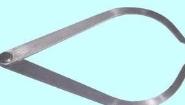
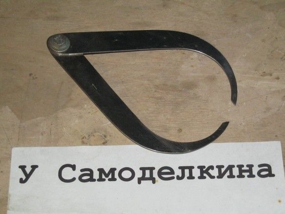
In the photo - for measuring the outer diameters and dimensions of parts.
Today, such a device is used in production for measuring the outer diameters and dimensions of parts (one category of tools), as well as for determining the dimensions of the inner diameters of parts (other models fixtures) In medicine, this tool is also widely used in various industries, however, all its varieties are associated with microscopic elements, for example, in dentistry or neurosurgery.
According to the method of obtaining data, mechanical and electronic models.
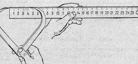
This instrument, as a measuring device, does not need to be verified, because it is not included in the state register. To compare the dimensions of the details of any object with the exemplary dimensions, just this type of caliper is used. So, having measured the detail by such a specific method, the obtained data are compared with the data of samples, from which conclusions are drawn.
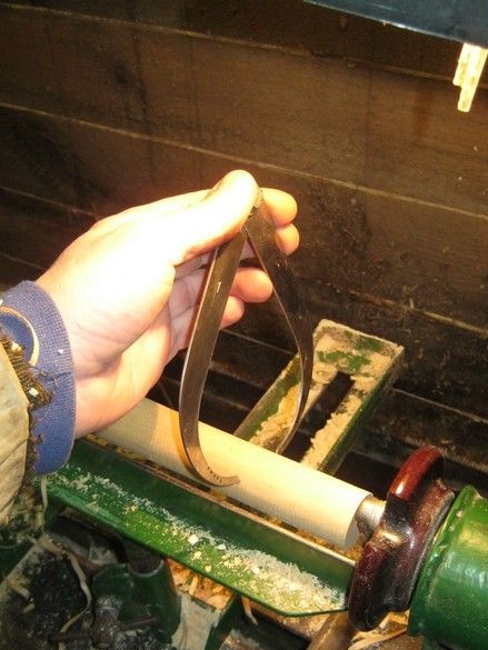
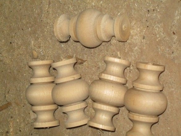
The caliper is also very convenient in turning, especially among woodworkers - indeed, when turning decorative parts from wood, the exact dimensions are often not very important and a tool that allows you to quickly, on-the-go assess the size of a part or workpiece is popular. The caliper is especially convenient when turning identical parts, and such a task arises before each turner regularly. The availability of several such tools extremely accelerates the matter - you can pre-configure them for the main dimensions of the part and not be distracted by measurements with a ruler or caliper.
A simple caliper, like in the photo above, is not difficult to make yourself. It can be seen that the difficulty is only to choose the right material, then a little simple metalwork.
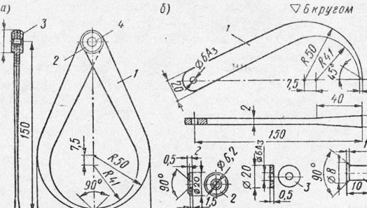
In the drawing, a caliper with a measurement diameter of up to 180 mm.
What was used in the work.
Tool.
A set of ordinary bench tools, something for drilling holes. I used the simplest grinding drum installed in a wood lathe. I used a small angle grinder with a thin cutting disc, an electric sharpener. Useful stamps with numbers. Do not do without a steel plate or anvil.
Materials
A piece of sheet steel of suitable thickness. Used stainless, 1.5 mm thick. It is desirable that the workpiece is flat, without dents. Medium-sized sandpaper. A little hardware.
So.
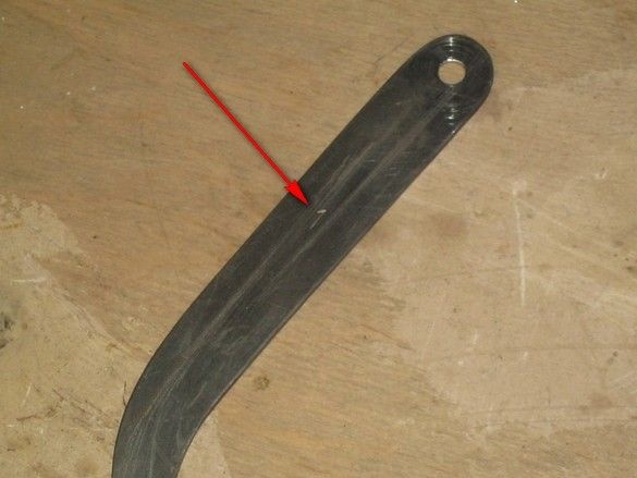
In the manufacture of the tool, several deviations from the drawing were allowed - the caliper legs were taken of the same thickness, instead of a rivet, I used an ordinary M6 screw. Practice has shown that two reinforced "body" washers and a stop washer allow the legs to move smoothly, with little effort. By tightening the nut, it can be adjusted.
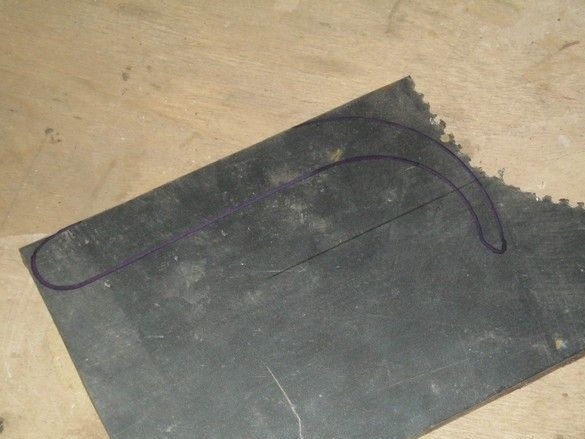
The caliper leg drawing was printed on a printer on thick paper, fitting the size to the required one. Cutting out, I got a template. The contour of the legs can be transferred to the workpiece using carbon paper.
All that is possible is cut off by the "grinder". The difficulty is cutting out the inner radius. He had to be cut out with a very small “remnant” of the cutting disc.
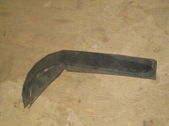
After rough cutting, I finished the outline on the grinder and with a magic file.
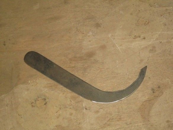
Here, again, there is a problem with the inner radius. I solved it by making a small grinding drum from a birch block of wood with a radius slightly less than the inner radius of the caliper leg. Without removing it from the machine, I wrapped a sandpaper on the block, fixed the ends with adhesive tape.
After complete refinement of the shape of the legs, holes for the hinge were drilled.
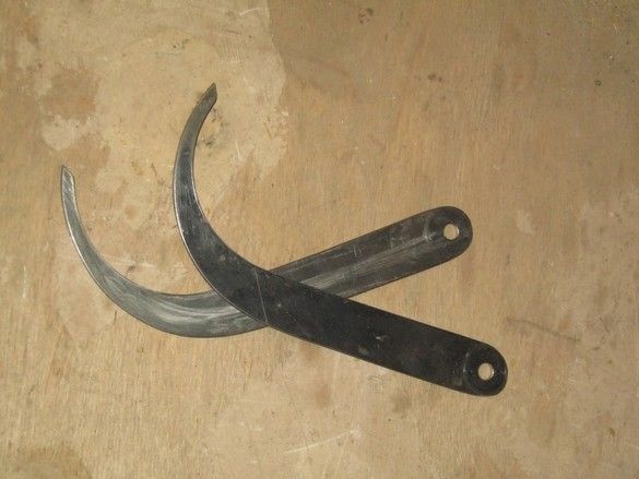
An M6 bolt of suitable length is selected, the legs are fastened with an impromptu hinge. It turned out simply and quite efficiently, moreover, the force with which the legs move can be adjusted.
You can recommend an alternative manufacturing option, more, hmm, classic - without dancing with angle grinders. A number of holes with a diameter of 4 ... 5 mm are screwed and drilled along the contour of the legs. A small chisel cuts the jumpers between the holes. Further the same.
The hardening of the working part of the legs is omitted and when using the tool not only for pieces of wood, it would be better to do it:
- heat the working parts of the legs to a length of 20 mm to a light cherry red color of red-hot and cool through a layer of oil in water;
- Unscrew the caliper legs after hardening and clean with an abrasive cloth.
Some changes can be made to the described caliper manufacturing sequence.
If the workpieces for the legs are small in size and geometrically marking them is inconvenient, then two templates are made of thin sheet steel for their marking: one for drawing lines on which it will be necessary to tilt the centers for auxiliary holes, and the second (smaller) for marking the contour of the legs . Previously, they impose a pattern that represents a contour. First, auxiliary lines are applied to the workpiece according to the first pattern, and then the main ones according to the second pattern are smaller. The latter is set so that the lines of its contour are equally remote from the applied auxiliary contour lines for the centers of the auxiliary holes.
If the material on the caliper blank is a strip of 25X4 or 30X4 mm, then straight lines are drawn on them, reproducing the shape and length of the legs in an unbent form. Then the strip is chopped off with a chisel on a stove or in a vice, backing 0.5-1 mm from the marking line, and filed rough. After that, the leg is heated and bent by hammer blows on a round mandrel, the dimensions of which correspond to the bend radius of the legs.
The final processing of the calipers does not differ from the sequence given above.
With this method of manufacturing the calipers, less time is spent, since there is no need to drill auxiliary holes along the contour of the workpiece. The latter method is most often used in the manufacture of caliper, as the bending of the ends of its legs is very simple, while the bending of the caliper legs is a rather complicated operation that requires certain skills.
Caliper test and technical requirements. The caliper test consists in the divorce and compression of its legs. In this case, the stroke in the hinge should be smooth, and the ends of the legs should fit tightly. Caliper surfaces should be clean, free of scratches, nicks and dents, and sharp edges blunt. The ends of the caliper legs should be hardened to a length of 20 mm to a hardness of HRC 40-50.
It remains to say that the tool in the arsenal of a wood-turner is in great demand. Practice has shown that it is better to have a few pieces. At the same time used, a maximum of four.
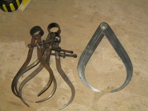
In the vast majority of cases, however, one or two is sufficient. To avoid confusion when using multiple tools, you can knock out a serial number on the legs.
Usage usually consists in measuring the diameters of the workpiece when turning identical parts. At the same time, the detail-sample is machined, focusing on the required connecting or overall dimensions, the rest will tell you how the heart is. All of the following parts are machined according to its size — with the help of several calipers, the main dimensions are “removed”, usually one or two diameters and length. In this case, it is better to add diameters per millimeter - grinding allowance. All. Turning the likes turns into sheer pleasure.
The workpiece is machined until the caliper with the largest diameter begins to fail. You can measure directly on a rotating workpiece, while the caliper legs should be applied to the workpiece at the same time. Otherwise, the tool may be pulled out of the hands.