» Electronics »Thief guard

Thief guard


In search of an interesting solution for locking the doors of the workshop, I looked through many options for all kinds of locks, bolts, code devices.

Looking through the availability of various components in the workshop, I came across a board from a burned-out router. The idea came to assemble an actuator with a secret.

And from the old router I needed only one detail - the Internet cable connection jack.

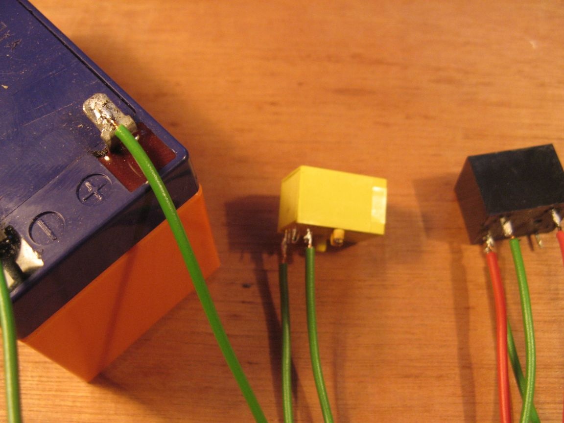
For the actuator we need:
- network socket RJ45;
- 12 volt relay;
- two RJ45 connectors;
- the battery for our relay, I have 12 volts;
- wires;
- soldering iron, side cutters, tweezers.

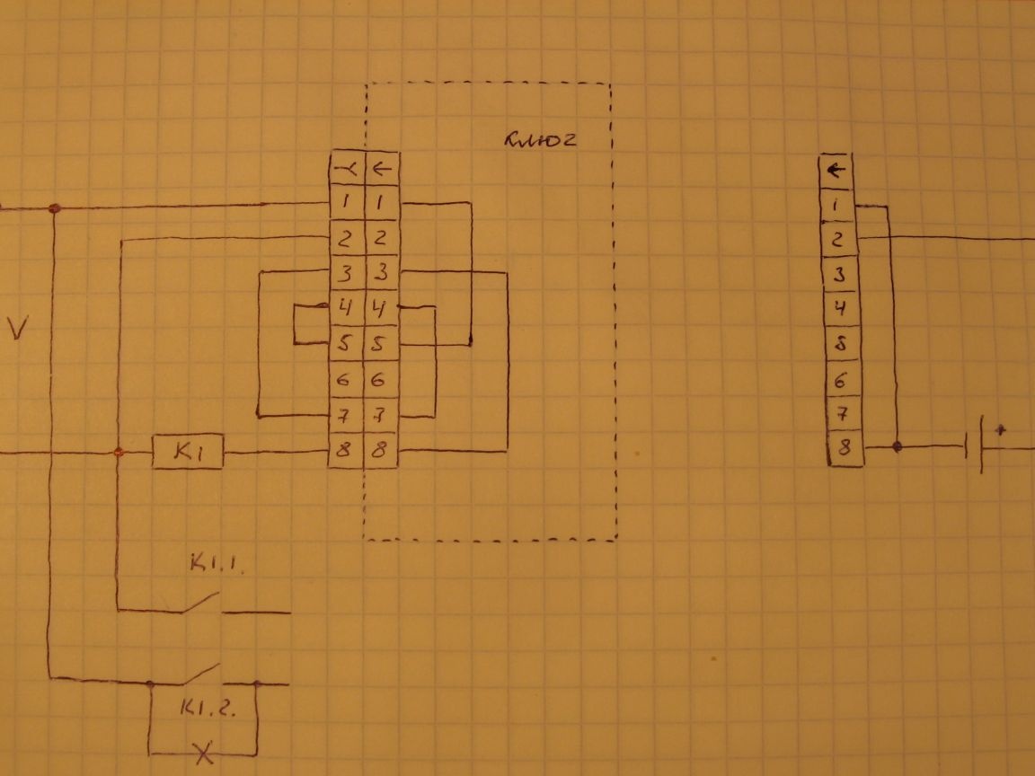
The circuit consists of an actuator and two types of keys. One, let's call him a worker. The second key is a master key or key for an emergency.

When the key is not connected, the relay is not active and the controlled device is in the off state. When we connect the key with jumpers, then minus the power supplied to the relay, and its contacts close. The controlled device turns on, for example, it will be a solenoid. The emergency key work, I will tell in the course of the description. I will also describe why one relay contact is closed by a jumper.

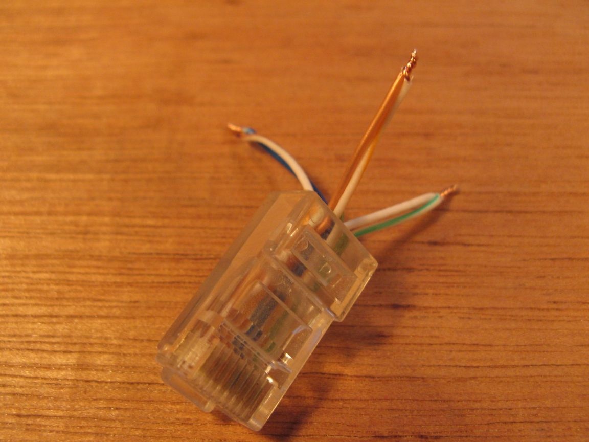
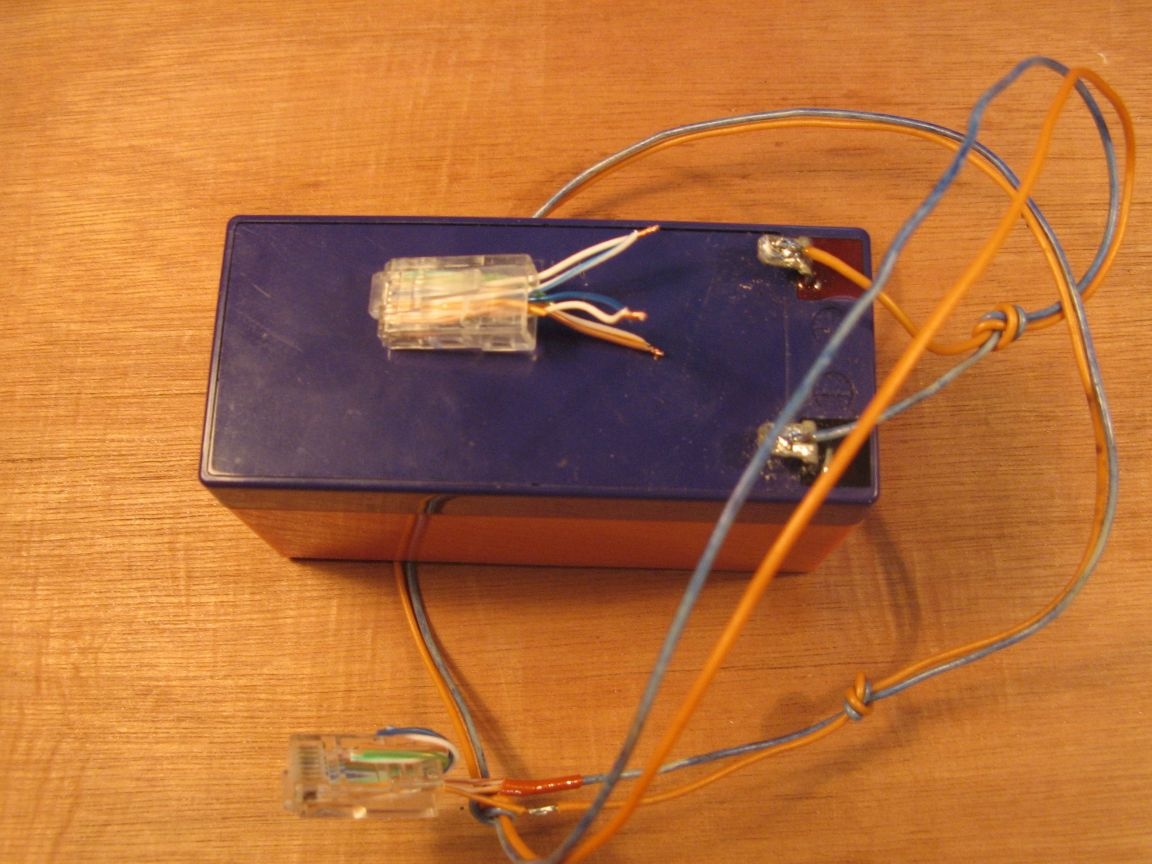
Take our RJ45 connector and crimp it. If there is no crimping tool, then you can take the old cable with crimped connectors. This option is more accessible.

Bite off with a margin, twist the wires for a while according to the scheme. Contact report produced from right to left. We have the connector wires to ourselves and the latch down.

The key is ready. Now go to the main device.

Everything is soldered according to the scheme.
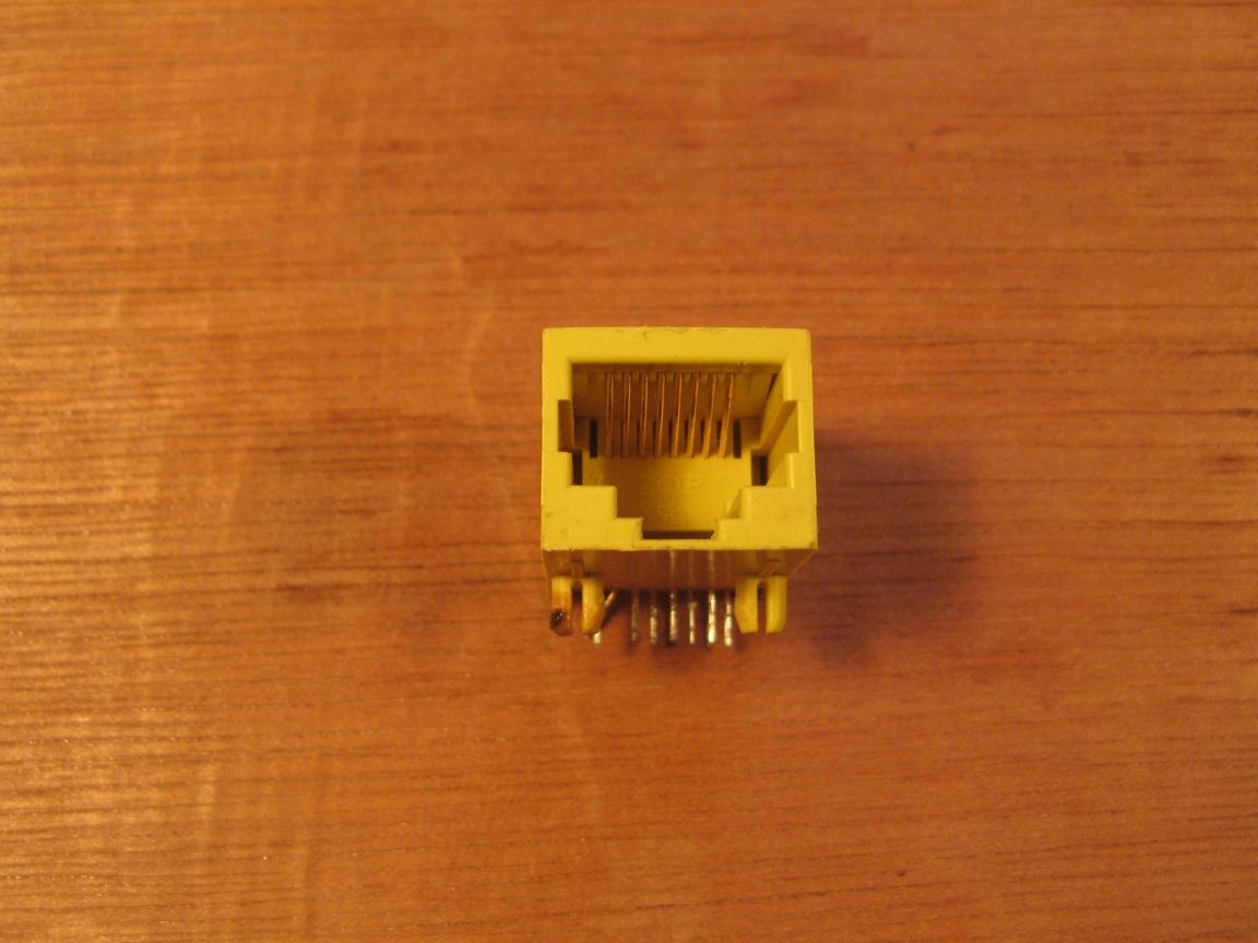
At this stage, we need an RJ45 socket. New or as I have soldered from an old router. The socket from the motherboard of the computer is very suitable, it often has LEDs installed, it would be useful to indicate the operation of the device.
We solder the jumpers with wires or just drops of solder.


I took the relay from the old board of some device. Initially, the circuit relied on a bipolar relay. After assembling the components, I found only a single-pole one, but it will also suit me.
Therefore, in the diagram, a jumper is drawn on one contact.


We solder everything according to the scheme. We produce the contact report from right to left or call the tester.


When everything is soldered, do not forget about the wire going from the second pin of the socket to a plus power. We need this wire for an emergency.

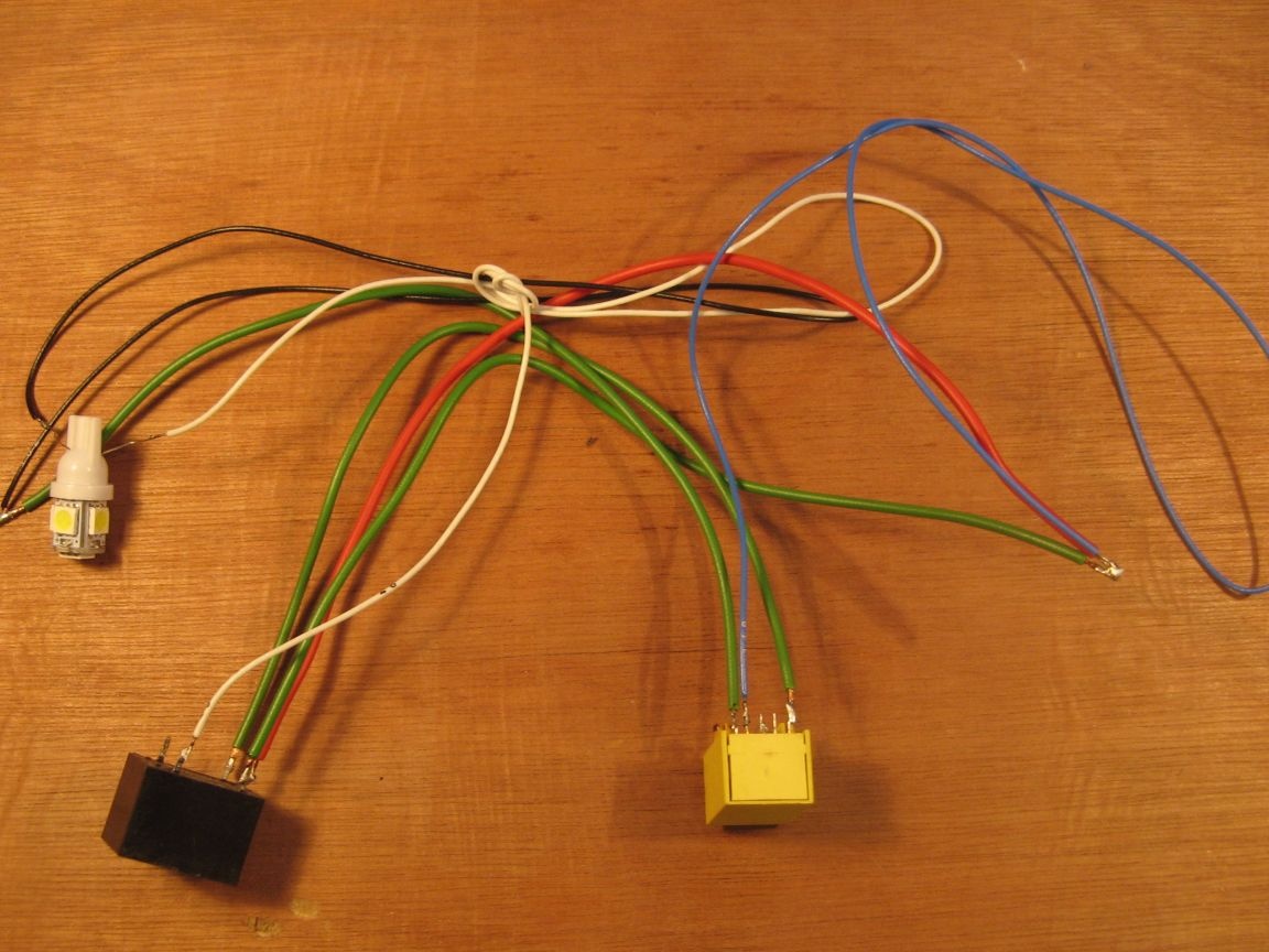
In the role of an actuator, or rather a demonstration of the operation of the device, I connected an LED light bulb (suddenly it will be necessary to control the light bulb). We stick our key into the socket and the light turns on.


We emulate a situation with a power outage, the battery is dead.
We solder our battery.


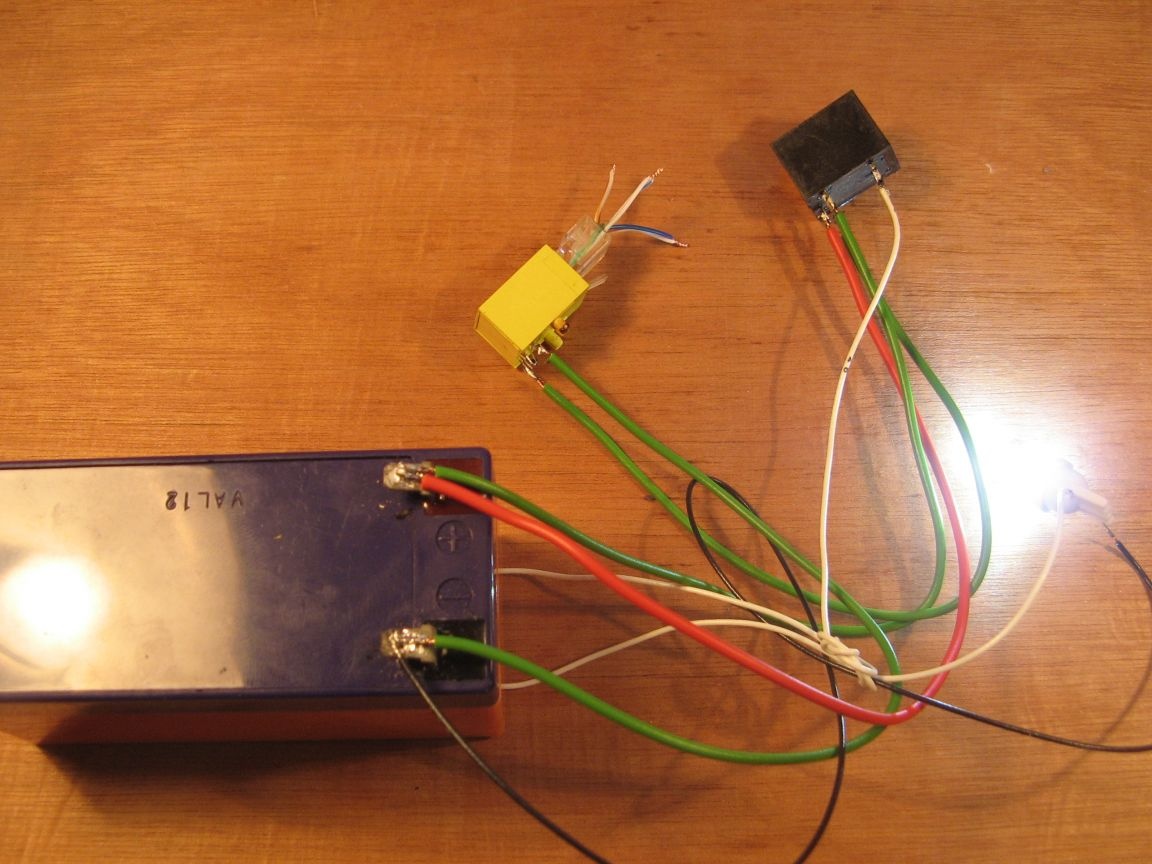
From the second connector we make a key master key. We unsolder the battery according to the scheme, the one that is drawn separately.


We connect to our circuit. Power is supplied to the relay winding, a plus is received through the emergency wire, which closes its contacts and our light turns on.


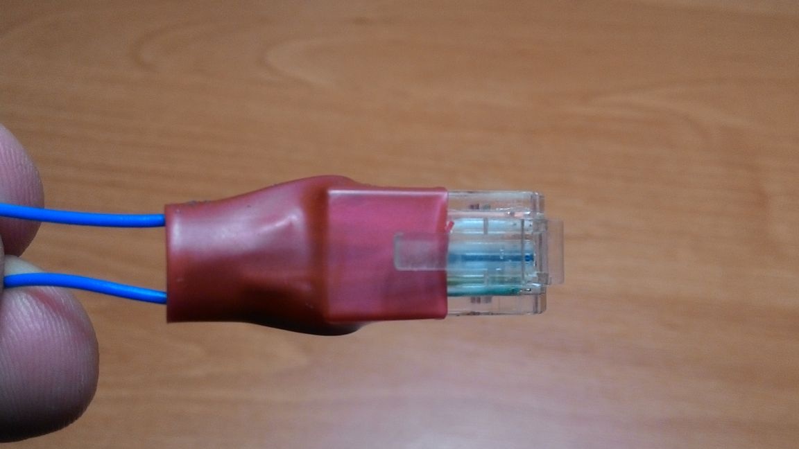
On the key, solder the twisted wires and isolate them. From the wire we make a loop for wearing. We shrink everything.


Such an actuator I did. Useful for opening the door of the workshop.


The video for the manufacture of this device, as always, is displayed on the video:

6.5
7.1
6.1

Add a comment

    • smilesmilesxaxaokdontknowyahoonea
      bossscratchfoolyesyes-yesaggressivesecret
      sorrydancedance2dance3pardonhelpdrinks
      stopfriendsgoodgoodgoodwhistleswoontongue
      smokeclappingcraydeclarederisivedon-t_mentiondownload
      heatirefullaugh1mdameetingmoskingnegative
      not_ipopcornpunishreadscarescaressearch
      tauntthank_youthisto_clueumnikacuteagree
      badbeeeblack_eyeblum3blushboastboredom
      censoredpleasantrysecret2threatenvictoryyusun_bespectacled
      shokrespektlolprevedwelcomekrutoyya_za
      ya_dobryihelperne_huliganne_othodifludbanclose
35 comments
A teacher of the Russian language came, without a single knowledge of physics))
On this topic.
It is necessary to make more on a reliable connector and pins so that it is. Diodes instruct.
Another option is to make a hole in the connector and put a button. I inserted an external connector, the button closed. Extra complexity.
Without a mating connector, close anything at the output; you won’t open it without pressing it.
The idea has the right to life, if you add more locks.
Or buy a radio-controlled relay and open it.
Author
Your comment is not clear. Where is not the law of physics?
Stumbled upon
[User offline]
popvovka February 17, 2018 9:33 p.m. Posted by -7
Reply Quote Complaint
Wryatle. [u] [/ u]
I didn’t want to read further, if with grammar everything is clear then physics as well as common sense are completely absent
in the city, yes, too many tracking systems. Maloli, you can have a camera or a GPS beacon in your car. And in the villages drunk trades different.

Drunk this connector will close immediately. immediately))) And not for the theft, but to see what happens. Our people are curious
Is anyone really considering this a serious lock for a safe? ))). It is understandable that this is a "castle from honest people" ...
... In the end, when was the last time anyone heard about the theft with penetration? ))) .. In the "Cop series" it is now, but is it real? ))))). The 90s are over ... Cars aren’t locking everyone now ...
Well yes. "Castle" with a trick level of 1 wire. It is enough for an attacker to spy that the owner sticks a connector with protruding wires in front of the entrance, then take the patch cord trim and try. And then it will either open or burn the castle. Both options are hemorrhagic to the owner.
And the hunt was messing around when a normally working touch-memori controller costs less than 1.5 ty?
It is necessary to add two more relays instead of jumpers on pins 3-7. All relays are connected in parallel, and their contacts in series. Moreover, the contacts of one relay work to open, and two to close. Then we switch jumpers on the key so that the closing relays would be powered. The emergency power key also energizes the closing relays.If you put all the wires in a heap during breaking, the third relay will open the power circuit of the executing device. Also, in the emergency power supply circuit (2), it is necessary to include a load (a bulb or something else) that would not affect the operation of the relay, in order to exclude a short circuit when contacts 1-2 are closed. And be sure to diode isolation as suggested by Ivan_Pokhmelev. The load in the emergency power circuit and diode isolation will reduce the likelihood of contact burnout during short circuit and, accordingly, device failure
There will be nothing for the laptop. Read about PoE when the line is specially supplied with voltage to power devices such as webcams, routers, etc. Network cards must withstand voltages up to 60 volts.
Insert the battery into the key, in my opinion is optimal.
In general, of course, a system with a cascade of relays is a good idea, but not with a connector but with buttons. And the unused buttons reset the cascade to "zero".

When I was serving an emergency, I was given the task of making a combination lock on a room with a "cross". As always, “the task is clear, give birth to the materials!” ... You’ll do it - leave, you won’t do it - your lip, and then you will rot in your clothes! )))) ... Well ... As usual then it was ...
... Found on this very cross a bunch of different relays. I assembled a cascade of them. The reset was organized by a reed switch on the door. Later it turned out that one more reset was needed, except for the "automatic" one - if it was incorrectly poked and the door did not open. Brought it to "0". The lock is some kind of retracting from the truck (I don’t know for sure. At the KTP at the ensign I traded “voles” for 100 meters). He collected everything in a large wooden box, which was inside. On the top of the box lid there were “gallets” so that “codes could be changed” ... On the doors, or rather, on the jamb, there was some kind of aluminum box from something. There are 10 buttons in it without fixing ... Well, such ... brown ... With a gadget ... Based on the "microtum switch" ...))))) I lifted up, I remember, with a bayonet-knife, drill holes for them .. I didn’t find another tool ...
Washing - 24 Volts. (There was such a line ... I don’t remember what it was used for ...)
P.S. I went on vacation ....)))
Author
I represent a cracker with a laptop)))
I’m sitting like that and looking out the window at him ...
Author
When a master key is connected, voltage is supplied to the relay coil and to the load. The relay is activated and the voltage from an external source through the relay contacts is supplied to the controlled device.
Threat. I'm trying to imagine the line of behavior of the attacker. Now, if I saw a network connector at the door. I would hardly have thought that it was a castle. The first thought is that the dude brought out the Internet to himself in the porch or on the street. The second thought is to pick up the beech and check. The result - pipets laptop. After that, I would do everything in my power to spoil the life of the owner of this "castle". I would fill everything with glue and foam, bump into this connector 220, and I probably would have come up with something more than once .... In general, of course, a system with a cascade of relays is a good idea, but not with a connector but with buttons. And the unused buttons reset the cascade to "zero". Or another option Arduino+ RFID + relay. Also normal, inexpensive and not difficult.
The author made three jumpers in the key: 1-5, 3-8, 4-7. Apparently in this way an attempt is made to create a "secret cipher". But instead, just jump 1-8 and the whole "cipher" goes on the drum.
This is an attempt to break into the castle. There, what kind of wire the attacker will have, this will be so.
If you make external switching with a thin wiring or a resistor of several ohms, then nothing will burn off inside, the maximum will look for the contact and that's it.
1. That's right.
2.A jumper 1-8 on what?
In fact, everything will be more interesting. On the first pass, you immediately do KZ 1-2. The circuit wires immediately fade away. Of course, you may not understand this straight away, and be transported to no avail for another half hour.But the most interesting thing will be when the owner comes to open the door .....
1) To open the lock, it is enough to close only the first and last contact on the key.
2) When a master key is connected, only the relay will trip. The device controlled by it will remain de-energized, so there is no sense from such a master key.
You don’t understand that all of your jumpers on pins 3 through 7 are superfluous, because a key with a jumper 1-8 will open the lock with exactly the same success as yours with a bunch of jumpers.
To open such a "protective device" is elementary. The logic is this. I do not know what is on the other side of the door. There is a connector for 8 wires. We take and in turn we close with the foot 1 all the others. On the first pass at the very end we get to a combination of 1-8. Whoever called the signal cables knows what I'm talking about.
Therefore, there should be not one relay, but at least 2. And one should prepare the power circuit of the second. Given that everything is powered by a network source, the reels can be hung a whole garland yahoo
Author
If you do not understand, I explain.
The minus power is 1 contact, it also powers the controlled device.
8 pin, feeds the relay.
The power plus is a 2 pin common to the relay and the controlled device.
And the key is not powered, in the key are banal jumpers.
Quote: popvovka
That is, by making jumpers in random order, will you masterfully determine the desired jumper there? As a minimum, it takes time to figure out which ones to close. The choice of jumpers is random, for example, in the diagram.
You have jumper 1-8 on the emergency key. Since they can be opened, then all the other jumpers are superfluous! How do you not understand this?
Quote: popvovka
During the time that I know about batteries, I didn’t see a short circuit at the output! Cs banks, yes. Given that I work a year and a half with them very closely.
It is not written for you from which source the key is powered, I proceeded from the option of power supply.
Author
That is, by making jumpers in random order, will you masterfully determine the desired jumper there? As a minimum, it takes time to figure out which ones to close. The choice of jumpers is random, for example, in the diagram.
During the time that I know about batteries, I didn’t see short-circuit at output! Cs banks, yes. Given that I work a year and a half with them very closely.
Quote: popvovka
Additional complexity is added with the number of jumpers.
Where does the additional complexity come from if it is enough to connect 1-8?
Quote: popvovka
What a short circuit, short circuit I know, and what a short circuit of a standard source is, alas, I do not understand.
Well, if you do not understand jargon, I will speak in more precise terms. A short circuit (jarg.) Is the same as a short circuit, that is, the result of shorting (jarg.).))
Author
Additional complexity is added with the number of jumpers.
What a short circuit, short circuit I know, and what a short circuit of a standard source is, alas, I do not understand.
The stump is clear, not constantly. Why on a regular key extra jumpers instead of one 1-8?
If a regular source with a short circuit at the output fails, then without emergency diodes your emergency key will not work.
Author
The foreign key serves only to start the device. It will not be connected permanently.
Quote: popvovka
In general, the device was designed for fun ...

Of course, a toy she is a toy.
On the main key, contacts 3 through 7 give rise to additional unreliability, you must immediately make jumper 1-8, as on the emergency key.
Two diodes must be added: between + and coil K1, and also between pin 2 and coil K1, cathodes to K1. This is necessary so that a failed regular source does not plant an external emergency battery.
Author
Wryatle. I have ouzo machines in my workshop. Smoke detector. Then quickly burn off the socket pin))
If you close all the contacts in the socket, then short-circuit the battery. The wires will heat up, the wiring will light up and the workshop will come to a full kirdyk.
Author
Then no one will hit the door)
In general, the device was designed for fun ...
And if I close all the contacts in your socket at once?

We advise you to read:

Hand it for the smartphone ...