» Electronics »High-voltage generator from ignition coil, cooler and mosfet - easy and affordable

High voltage generator from ignition coil, cooler and mosfet - easy and affordable


Hello everybody! The network has many high-voltage generator circuits that differ in power, in assembly complexity, in price and in the availability of components. This homemade assembled from practically waste parts, anyone can assemble it. This generator was going to, let’s say, for informational purposes and all kinds of experiments with high voltage electricity. The approximate maximum of this generator is 20 kilovolts. Since the mains voltage is not used as a power source for this generator, this is an additional plus from a safety point of view.


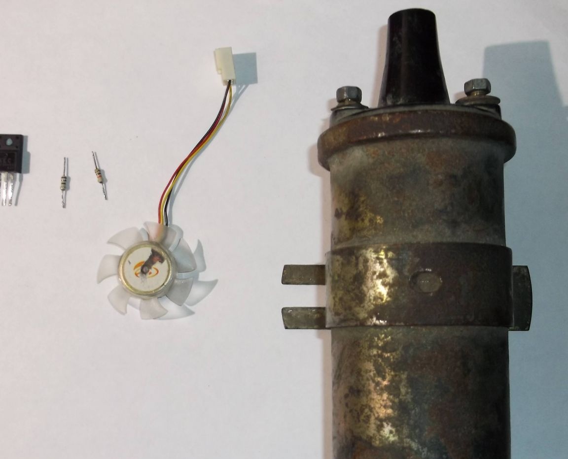
In the photo all the necessary parts for assembling a high-voltage generator.


To build, you will need:


VAZ ignition coil
Cooler with Hall Sensor
"N" channel mosfet
100 ohm and 10 kOhm resistors
Connecting insulated wires
Soldering iron
Terminal block (optional)
Mosfet radiator
Several screws
Plywood base for mounting parts


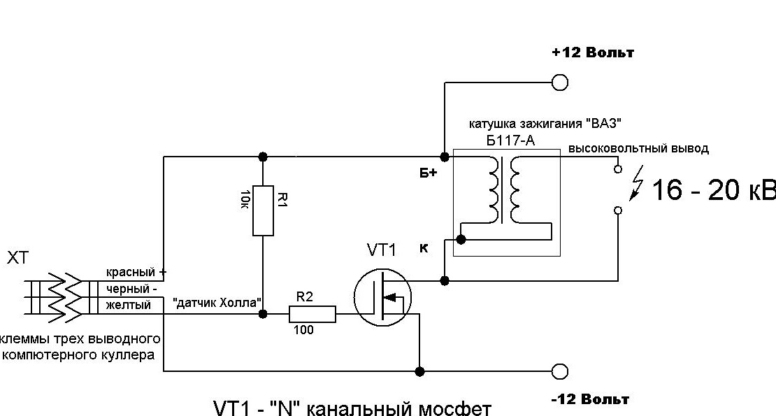
This is a diagram of this generator.


To whom it is interesting I will try to tell in more detail. As a pulse generator, a computer cooler or similar 12 volt cooler is used, but with one condition - it must have an integrated hall sensor. It is the hall sensor that will generate the pulses for the high-voltage transformer, in which, in this case, the ignition coil from the car is used. Choosing a suitable fan is very simple, as a rule, it has three inputs.


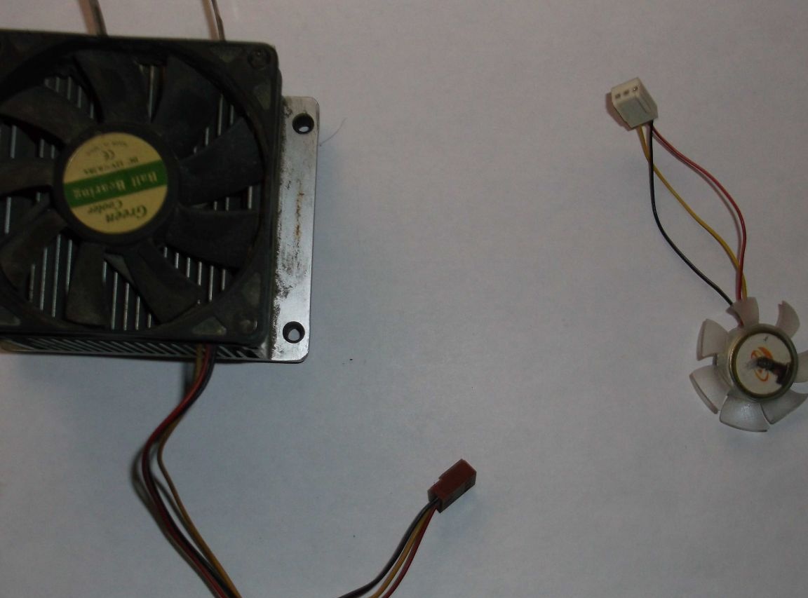
The photo shows the presence of three conclusions. The standard colors are red output plus power, black - common (ground) and yellow - output from the hall sensor. When power is supplied to the fan at the output (yellow wire), we obtain pulses whose frequency depends on the speed of the electric motor of this cooler and the higher the voltage, the higher the pulse frequency. The voltage should be increased within reasonable limits - about 12-15 volts, so as not to burn the cooler and the entire circuit. The resulting pulse signal has to be fed to the ignition coil, but it needs to be strengthened.


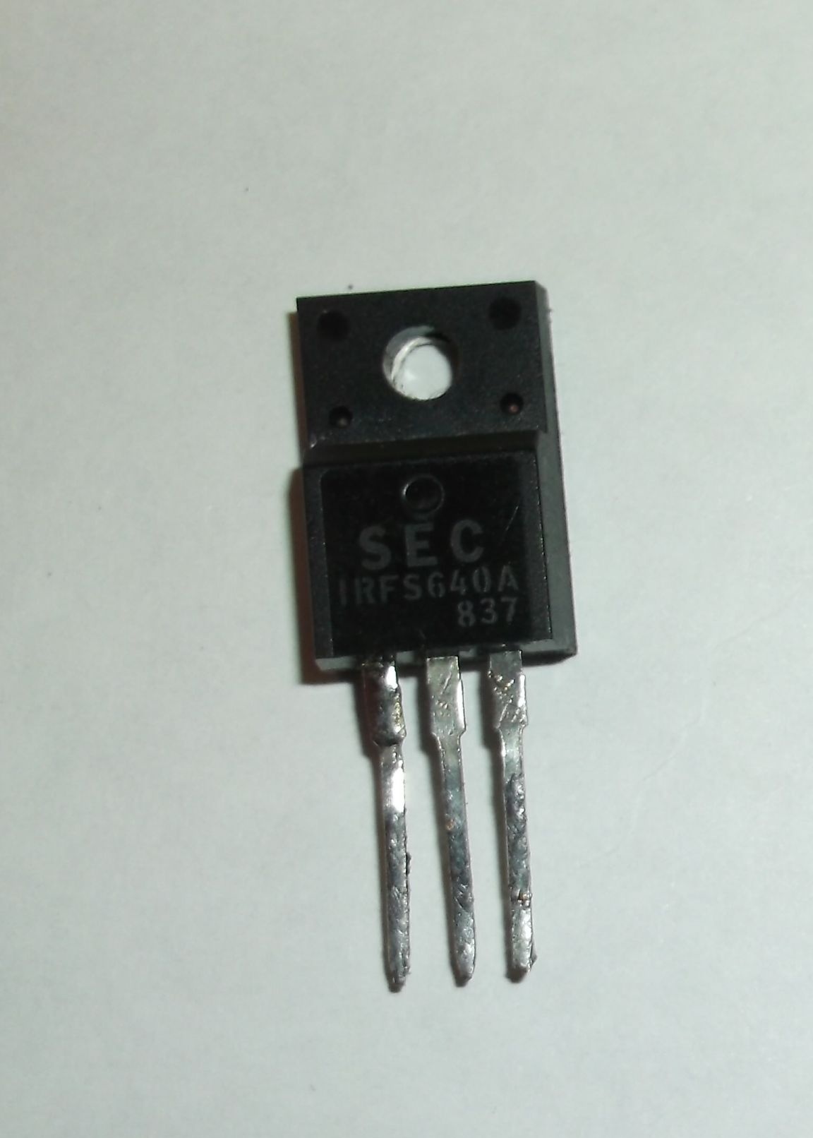
As a power switch, I used an “N” channel field effect transistor (mosfet) IRFS640A, others with the same parameters would be suitable, or approximate for a current of 5-10 amperes and a voltage of 50 volts for reliability. Mosfets are present in almost all modern electronic schemes, whether it is a computer motherboard or a starting circuit of an energy-saving lamp, which means that there will be no problems finding a suitable one.


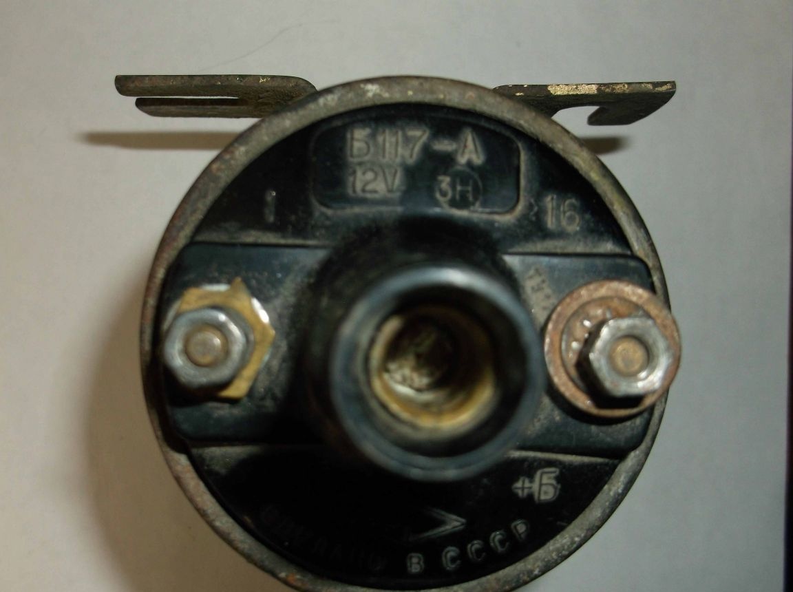
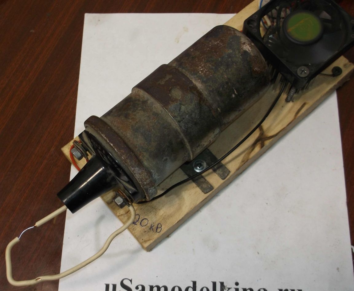
The ignition coil from VAZ "classic" B117-A cars has three outputs. The central one is a high-voltage output, “B +” is a positive 12 volt, and the general “K” is probably not marked.

Initially, the circuit consisted of three components: a cooler, a mosfet and a coil, but after a short time it broke, because either the mosfet or the hall sensor failed. The output is the installation of 100 Ohm resistors to limit the inrush current from the hall sensor to the gate, and a 10kΩ pull-up resistor to lock the mosfet in the absence of a pulse.


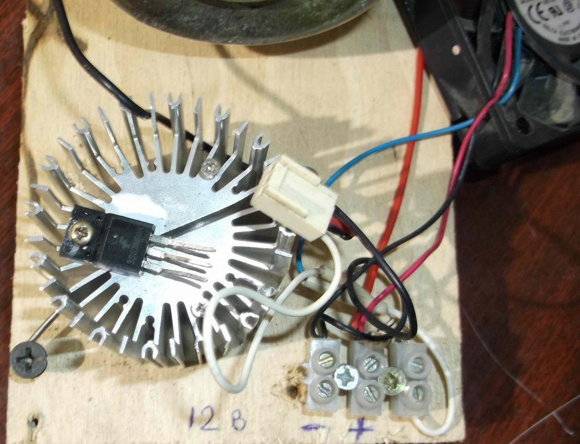
When assembling the circuit, the transistor should be installed on the radiator, preferably using thermal paste, since the heating during operation is significant.


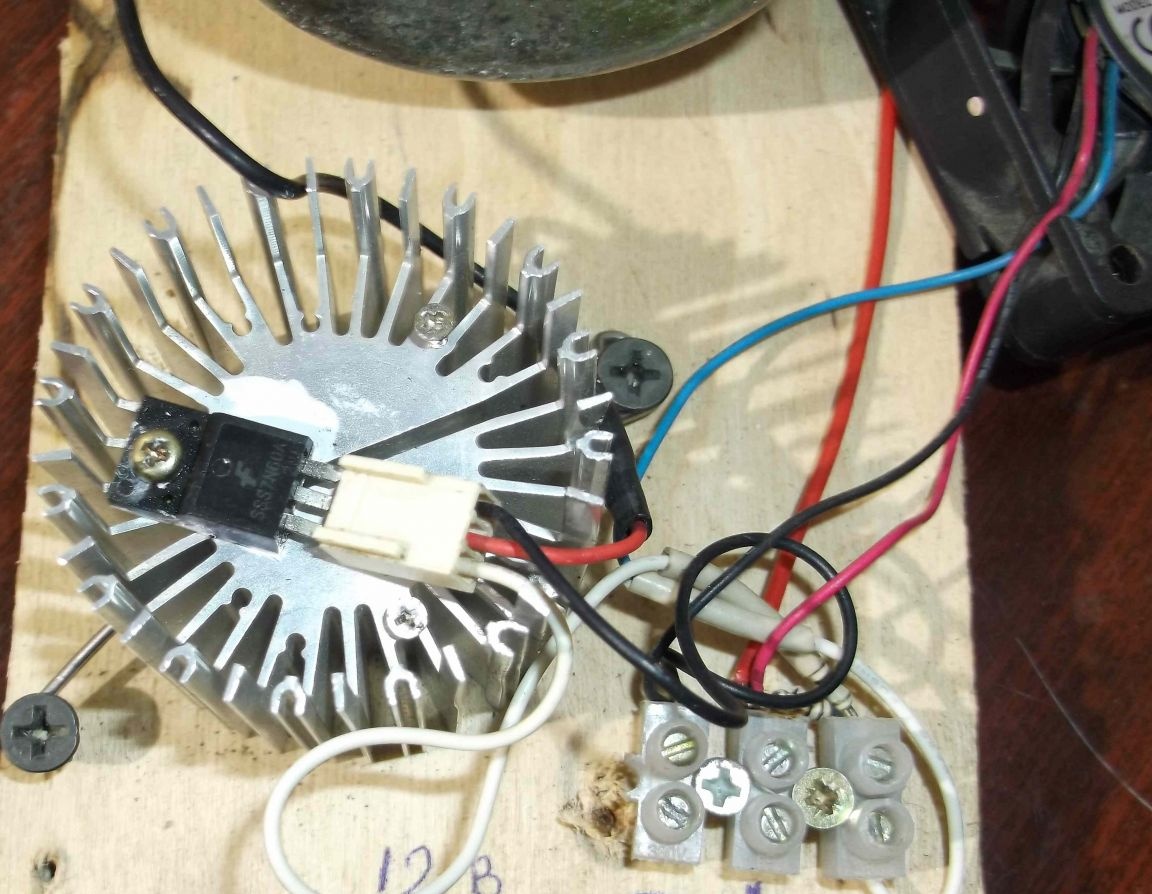
The connector from the cooler was used as a terminal block for connecting a mosfet. As a result, the need for soldering the transistor has disappeared, to connect or replace it is enough to connect the block to the terminals of the transistor.


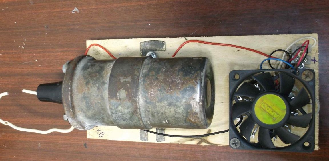
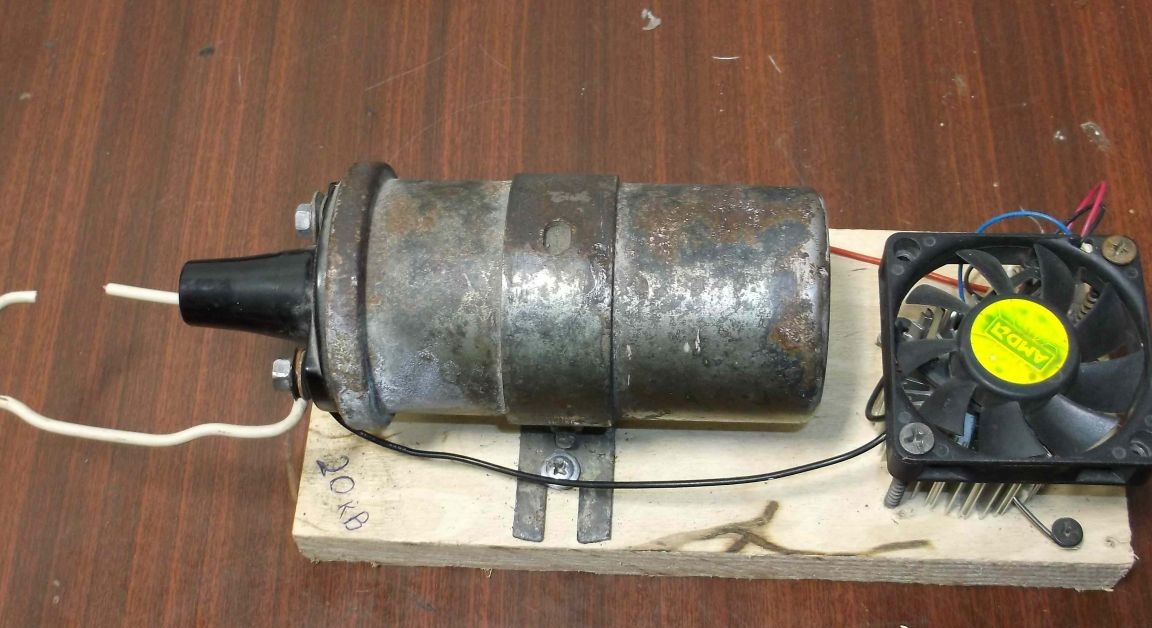
The fan was fixed on top of the radiator with two screws. As a result, it turned out that the cooler plays a dual role - as a pulse generator and as additional cooling.


We connect the power of 12-14 volts from the battery and try to work.

For lightning on wood, this unit is certainly weak, but what is high voltage with this homemade product can be estimated.

8.4
8.6
7.6

Add a comment

    • smilesmilesxaxaokdontknowyahoonea
      bossscratchfoolyesyes-yesaggressivesecret
      sorrydancedance2dance3pardonhelpdrinks
      stopfriendsgoodgoodgoodwhistleswoontongue
      smokeclappingcraydeclarederisivedon-t_mentiondownload
      heatirefullaugh1mdameetingmoskingnegative
      not_ipopcornpunishreadscarescaressearch
      tauntthank_youthisto_clueumnikacuteagree
      badbeeeblack_eyeblum3blushboastboredom
      censoredpleasantrysecret2threatenvictoryyusun_bespectacled
      shokrespektlolprevedwelcomekrutoyya_za
      ya_dobryihelperne_huliganne_othodifludbanclose
19 comments
GUEST GUEST
Nruter, you are wrong! In the diagram you depicted, a coil is used, where one terminal of the secondary winding is connected to the coil body. Therefore, for the occurrence of a spark, EMF is exclusively used for the secondary winding. Later coils were used, where the ends of the primary and secondary windings were connected together and brought to a separate clip. In addition, the windings were wound ACCORDINGLY. This means that the EMF of the primary and secondary windings were FOLD. Therefore, the secondary winding received already fewer turns than before. This saved the copper wire. Conclusion: Do you want to remove EMF only from the secondary winding - connect as you painted. If you want to shoot EMF primary + EMF secondary - do as the author of the article drew. (This is preferable).
The trouble is that the author connected the lower electrode of the discharger with the channel of the field-effect transistor, but it is necessary, DIRECTLY, with (-) the battery. Imagine the picture: the pulse from the Hall sensor enters the gate of the field-effect transistor and closes it, thereby interrupting email. the current in the primary winding of the coil. A 20-volt EMF arises, instead of immediately leaving the (-) batteries through the spark gap, rushes to the CLOSED channel of the field-effect transistor. The energy is such that the closed channel forcibly opens, passing a frantic current, extremely wrinkled and heating the channel, and its part, at the same time, breaks through the insulated gate and rushes to the Hall sensor, killing it, and more to the (-) battery. To limit this completely unnecessary and harmful current, the author recommends using a 100 ohm resistor. Why a garden of mountains to dress?
By the way, the device is good for checking car electric candles for a spark.
Thank you, the reason is in the battery, for some reason it quickly discharges. the transistor does not heat up at all.
Author
I had something like that but I don’t remember the solution to the problem, the Mosfet might have overheated and after a short break the circuit works (I honestly don’t remember but something like that happened) !!!
Tell me what the reason is, I’m starting, at first the discharge is stable at a distance of about 10-15 mm, after a few seconds everything fades and it’s not possible to start even approaching the contacts in the arrester. You have to turn it off, wait and turn it on again. Battery from a screwdriver 12V 2A.Maybe the current is too small in the primary winding? Thanks.
Here a contactless ignition circuit is implemented, as on the VAZ-2109. The field effect transistor in this case is a switch.
I remember I turned it on directly, I forgot to turn it off, the engine worked for a while. Heated terribly, but did not burn. By the way, by the magnitude of the spark, I did not notice the difference between connecting directly and through a resistor.
Dear, do not confuse people. Varistor - a type of resistor that changes its resistance depending on the applied voltage. It was widely used in the personnel scan of tube TVs. A conventional nichrome wire resistance is used on an automobile ignition coil. And this product is called the "CVT". I wrote about this a little higher. The word “Variator” has many meanings and this is one of them. The variator is also called a continuously variable gearbox and a device for shifting UOZ on modern engines.
An additional varistor resistance is hung on the Moskvich coil to limit the current strength, since the coil is 9-volt! In operating mode, the starter is blocked by additional contacts of the retractor directly. Without a varistor, the coil overheats and burns.
Yes exactly! I completely forgot) And what is there in the scheme there is no kander?
There is a capacitor on the Zhiguli coil. It is mounted not on a coil, but on a distributor with a screw to the body. Its output is connected directly to the breaker contact. Without a capacitor, the spark will be very weak, in some cases it will not be at all. The principle of spark formation on the secondary is based on the charge of this capacitor. When the breaker contacts are closed, current flows through the primary, the capacitor is shorted. When the contacts break, the capacitor begins to charge and a spark occurs. The coil in the photo has a variator - an additional wire resistor. He closes when the starter. The rest of the time it serves to limit the current through the primary.
And for many days I was fucking one day, which I just didn’t do, is not gaining momentum and that’s all, sneeze. regulated the gaps in the candles, not once dismantled the carb ... In general, a nightmare. Then I thought of it, took off my native Kander and hung two ceramic ones. Bzhik ... went like a plane. Insidious thing)
Yes, my wire from the Conder broke off somehow, it took me half a day until I understood the reason. So if he had fallen off the infection, otherwise it would have seemed to hang on the spot.
And why is there no capacitor on the Zhiguli coil? But on the Moskvich B115V, a capacitor is required, without it the spark is so weak that the motor only works at idle, and then, a good motor ...
Can I hang a Kander on this coil?

By the way, Moskvich coils are much more powerful.

I wonder if there is enough current strength of the high-voltage component of this gravitsapa on a wire laid along the top of the hedge around the garden section, 90 m long? I would have an electric shepherd so that thieves do not climb into the garden ...
Author
Nruter understood you - it is connected correctly, but the coil is depicted incorrectly in the diagram, I apologize !!! (the one who does nothing is not mistaken!) - this is me in my defense, and you definitely "+" !!!
She will work. Just not as it should be. Plus power must be connected to the junction of the primary and secondary windings. The current path through the secondary must be like this - + 12V --- secondary –– --- arrester –– mass.You have the same path + 12V --- primary --- secondary --- discharger --- mass. On this way, the voltage increase on the secondary will be prevented by the voltage drop on the primary. Plus, high voltage pulses will occur at the drain of the transistor.
Here is a typical diagram of turning on the ignition coil in a car
Author
It is turned on incorrectly, but the infection works. You would at least indicate the conclusions and how to connect, otherwise I don’t see the difference.
The coil should be included in the circuit as follows:

On your circuit, it is not included correctly.
I didn’t know that there are hall sensors in the coolers ... I’ll take a note

We advise you to read:

Hand it for the smartphone ...