Today I want to share instructions on the manufacture of original watches with a temperature sensor. As controller Arduino Uno. To display the clock, date and temperature, I will use a color LCD TFT screen. The screen uses many Arduino pins, so we can do without the RTC module.
To implement this project we will need:
- Arduino Uno
- LCD TFT 3.5 ”Shield for connecting to Arduino Uno
- ds18b20 temperature sensor
- Resistor 4.7 Kom 0.25 W
- Resistor 62 Ohm 2 pcs
- Battery Ni-Mn, 1.2V, 1000mA 6 pcs
- Blue LED 5mm 4 pcs
- Plywood 10 mm thick
- A little thin plastic or cardboard
- Sandpaper
- Electric fret saw
- Hot glue
- soldering iron
- Solder, rosin
- electrical tape
- Double sided tape
- connecting wires
- Acrylic paint
- Dyes for acrylic paint
- drill
- Drills for wood 5 mm and 3 mm
- Wood screws 3 x 30 mm
Step 1 Prepare the screen.
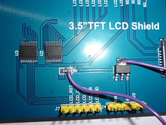
First, take the screen, before installing it you need to prepare a little. In my case, it looks like this:
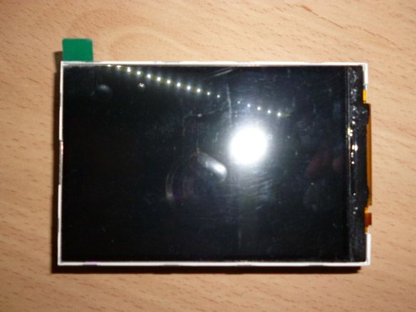
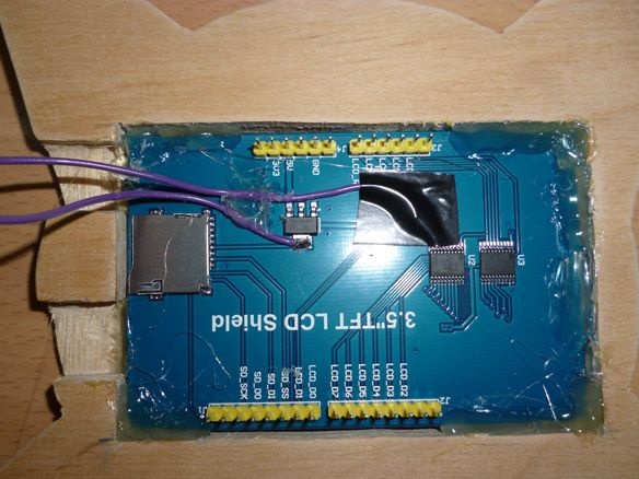
It may differ slightly from you, there are many varieties of them. The backlight is powered through a 3.3 volt stabilizer and a 5 volt resistor with an Arduino. This is clearly visible in the photo:
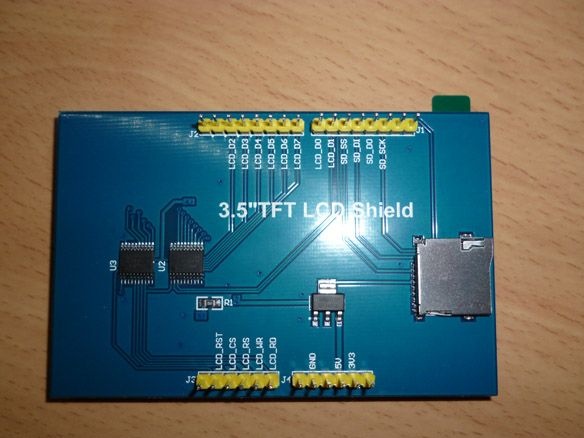
Such a scheme makes it impossible to control the backlight, but it is useful, to make the brightness lower at night, for example. To implement the brightness control, cut the track near the resistor and solder the wire connecting the output of the voltage regulator and the resistor. We glue the electrical tape on top so that there are no random faults. Then we cut this wire and connect it to the Arduino or just put the switch in the gap. The result should be like this:
The screen is now ready to install.
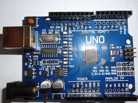
Step 2 Preparing the Arduino Uno.
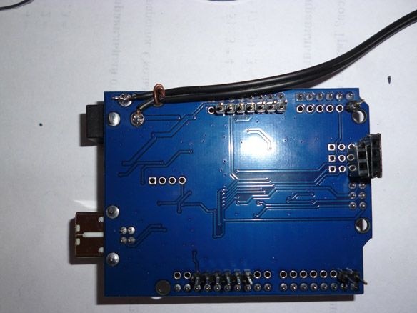
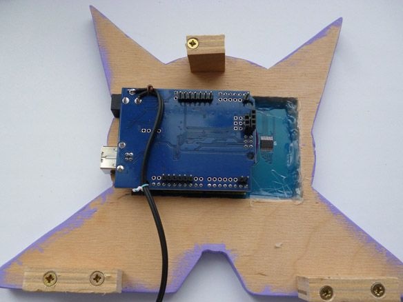
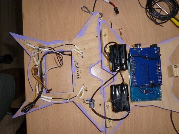
The screen uses many Arduino pins, in addition to this, a slot for an SD card is often placed on a board with a screen. Another problem is that when the screen and Arduino are connected, the remaining Arduino pins become inaccessible. Therefore, you need to choose an analogue of Arduino Uno with prepared additional landing sockets for pins. In this way, we can solder the comb to the free leads in the opposite direction. So, we will abandon the SD card slot in favor of free pins. Solder in the opposite direction the following conclusions: D0, D1, D10, D11, D12, D13, A5. Also, on the reverse side we will need +5 volt, GND, RES terminals. We will use Ni-Mn batteries for power, and it will be necessary to charge them, for this purpose we solder the wires to the Arduino power connector, so we can both charge the batteries and power the Arduino while charging.In the end, we get the following:
You can go to the body.
Step 3 Making the case.
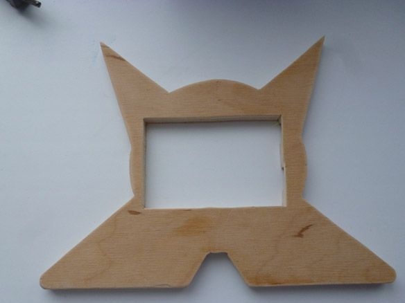
Let's start with the manufacture of the case for our watches. We take plywood 10 mm thick as the basis. The shape can be different and, if you did not like the shape I selected, you can make a template and cut it with your shape. But if you decide to do the same as mine, then print the following image on any printer at a scale of 100%:
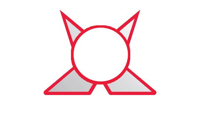
Cut the printed pattern along the outer edge. We attach the template to the plywood, draw and cut out, this time from plywood, two such details. In the first part, you need to cut a rectangle the size of our screen. To do this, we place the screen in the middle of our workpiece, note that you need to orient in the middle of the screen itself, the board on which our screen is located is not symmetrical. Therefore, in the middle we place the screen itself, and outlines the size of the board and cut out this rectangle in the workpiece:
Next, you need to connect the screen and Arduino Uno. We attach to our blank and mark on the plywood the places of cutouts for the USB port and the Arduino power connector. Using a knife, cut through the marked lines, but not to the end, but only to the desired depth:
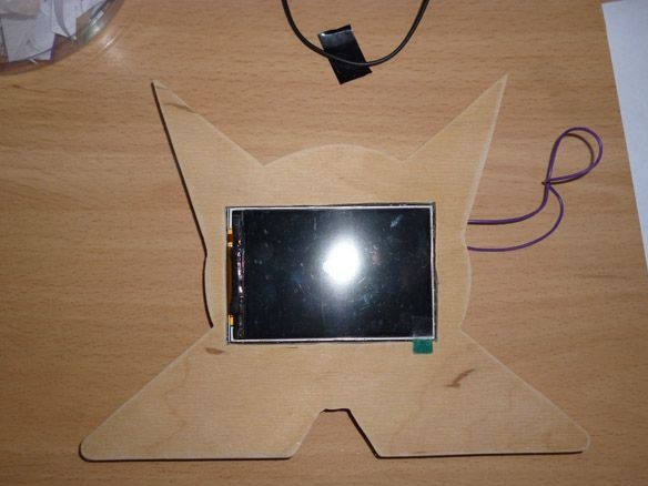
We put the blank from plywood on a flat surface, put the screen inside. A flat surface is needed so that the screen and the front of the workpiece are in the same plane. Please note that the USB cutouts and the Arduino power connector match their actual location. Using a hot-melt gun, glue the screen to the plywood, at the same time you can also glue the backlight wires so that they are not accidentally torn out:
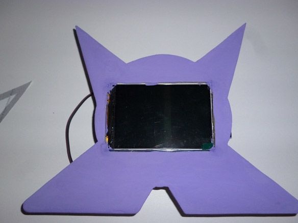
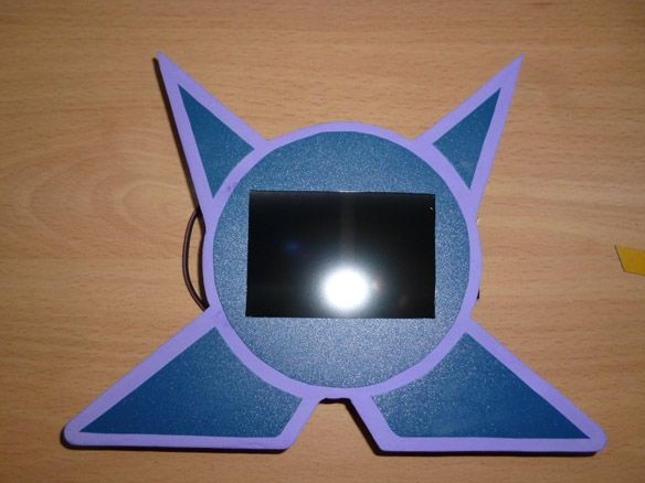
From the front side it will look like this:
We cover our blank with acrylic paint. I chose acrylic paint because it does not smell and dries quickly. Using the color scheme we give the white paint the color we need. I like purple. You can paint in any color you like:
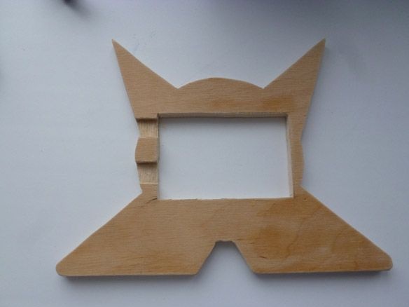
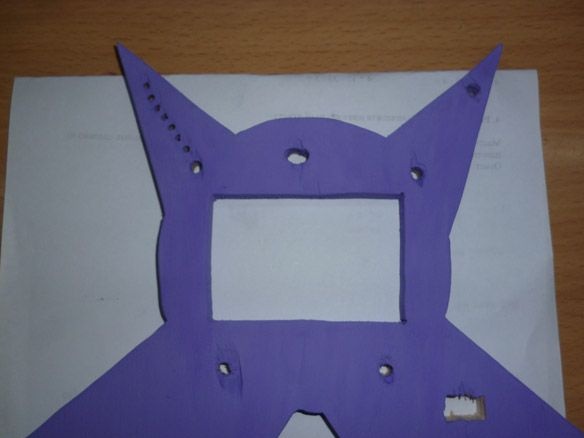
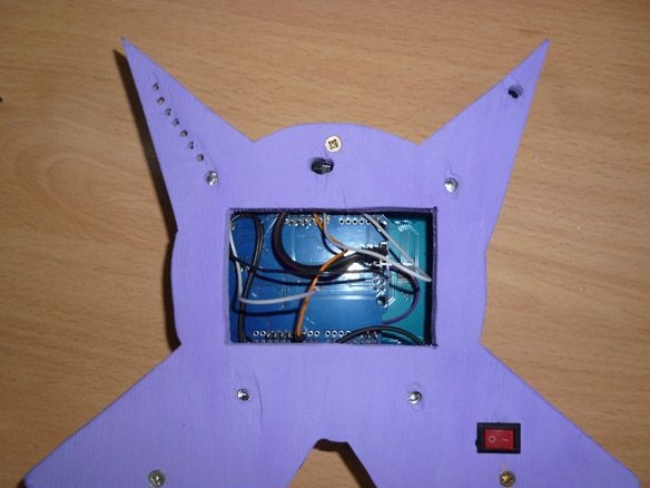
Now we turn to the second workpiece, in it it is necessary to cut a rectangle measuring 75 mm by 35 mm, to access the Arduino pins. And also it is necessary to make five holes with a diameter of 5 mm for LEDs. And a slot for the switch. And 3 mm holes for screws. As well as the first blank, we paint the second:
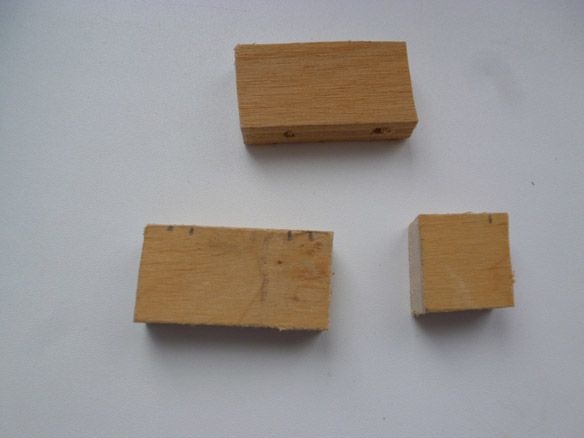
To connect these parts from plywood of the same thickness, we will produce two rectangles measuring 20 mm by 40 mm and one square with a side of 20 mm. And we drill 3 mm holes in them for self-tapping screws:
Step 4 Electrician.
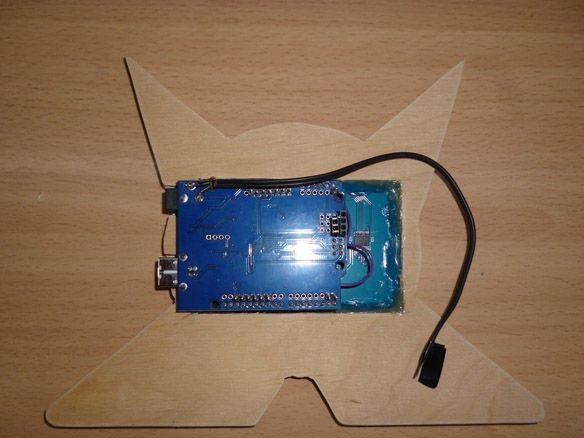
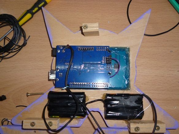
Put the Arduino in place:
We fasten our connecting rectangles as shown in the photo:
We take the batteries, solder them sequentially in three pieces, remove the wires and twist the electrical tape. We place them in the lower parts of the front billet, on the back side and glue on hot melt adhesive. The wire from the negative terminal of the Arduino power connector is soldered to the minus of the first three batteries. Plus solder from the first three to the minus of the second three batteries. Plus from the second three we solder to one of the contacts to the switch. The wire from the positive terminal of the Arduino power connector is soldered to the second terminal of the switch. Simply put: all batteries must be connected by a follower, minus from them is soldered to the minus of the Arduino power connector, and plus through the switch to the plus of the power connector:
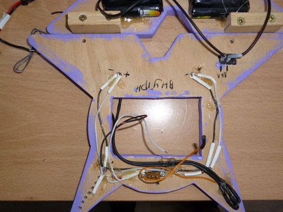
We pass to the back. We insert LEDs into the holes made and fix them with hot glue. We solder them in parallel with two LEDs and do not forget about the resistors on the dance wire. The minus from the LEDs is connected to GND, plus to the D11 Arduino.
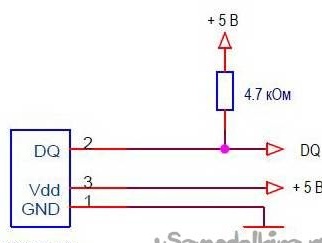
We insert the ds18b20 temperature sensor in the upper hole. It has high measurement accuracy, the error is not more than 0.5 ° C. The sensor is calibrated at the time of manufacture; no additional settings are required. Temperature measurement range -55 ... + 125 ° C. There are two modes of operation: with an external power source and “spurious power”. We will use external power, as it works more stable. The connection is as follows:
We also fix it with hot glue.Ultimately, you should get the following:
The DQ pin of the temperature sensor is connected to the D10 Arduino. Remember to solder a pull-up resistor between DQ and +5 (VDD).
Before final assembly, check again that everything is soldered and connected:
Step 5 Putting it all together.
Gently, so as not to tear the wires, flips the back and put it on the front. In the places of attachment of the connecting rectangles, we make holes and screw the screws, thus connecting both parts:
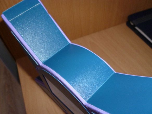
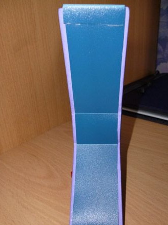
Now we cut out cavities with a thickness of 35 mm from thin plastic. On double-sided tape we glue these cavities in a circle on the sides of our watches:
Also, we cut out the internal elements of the paper template from thin plastic and stick them on the front of the watch:
To charge the batteries and operate the watch during charging, you need a 7.2 - 8 V power supply, with a current limit of 600 mA. If you have other batteries, then you need to select another power supply, the main thing is that the charging current does not exceed 10% of the battery capacity.
On this the assembly is completed, it remains only to edit and record the sketch.
Step 6 Prepare the environment and fill the sketch.
To edit and fill in the sketch, you first need to install the Arduino IDE from the official website:
www.Arduino.cc.
Then install the following libraries. To work with the screen, the UTFT library:
To connect the temperature sensor OneWire library:
To install these libraries, unzip the archives and place the unpacked files in the “libraries” folder located in the folder with the Arduino IDE installed. Or without unpacking the downloaded archives, in the Arduino IDE, select the Sketch - Connect Library menu. At the very top of the drop-down list, select the "Add .Zip Library" item. Do not forget to reboot the Arduino IDE after all this. Watch Sketch:
The temperature sensor works using the One Wire protocol and has a unique address for each device - a 64-bit code. In order not to look for this address every time, we connect the sensor to Arduino, fill in the sketch located in the File - Examples - Dallas Temperature - OneWireSearch menu. Next, run Tools - Port Monitor. Arduino should find our sensor, write its address and current temperature readings. We copy or simply write down the address of your sensor. Open the sketch Ard_LCD_TFT_Term, look for the line:
byte addr [8] = {0x28, 0xFF, 0xDD, 0x14, 0xB4, 0x16, 0x5, 0x97}; // address of my sensorWe write down the address of your sensor between braces, replacing the address of my sensor. It remains only to fill in the edited sketch. I would also like to say that it’s just a little boring, but you can write your own sketch. As I write other sketches for these watches, I will upload them.