They finally arrived, just like that, you didn’t hear it - an inverter without transistors, and even without double, symmetrical transformer windings!
Inverters, like DC voltage transformation devices, were not included, but simply piled into modern life. For example, solar energy can not do without them, motorists without inverters will not be able to watch TV for 220 V and so on again.
Let me remind you that an inverter is a device that converts a low (or high) voltage (mainly constant) into high (or low, mainly variable), that is, this device is a transformation of a constant voltage in any other, as a rule, with minimal power loss.
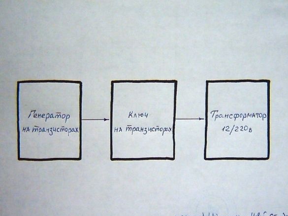
Converters of only alternating voltages are called transformers. Looking through a lot of schemes of invoices, you can see that everyone has transistors. Moreover, the transistors are predominantly those most expensive, field-effect ones that are afraid of excess discharges, static electricity, short circuits, they still need to be smeared with special heat-conducting paste (or glue) and put not a small radiator or fan on them.
And it’s still a hassle - to disassemble and wind a double symmetric winding in opposite directions on a transformer, stupidly - stressfully.
What is the principle of operation of an inverter without a transistor and what did I come up with here, huh?
Let's start with the classics:
Remember that it increases the voltage in the inverter, yes - the transformer. But the transformer can only work with alternating current, since only alternating current is transformed inside the inverter.
And in order to get this alternating current, transistor generators, mainly of low frequency, are used.
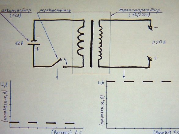
Here it is true, with one “but” - it is not necessary to use alternating current, you can also transform a constant, but intermittent current (pulsed, current type: "yes - no - yes"):
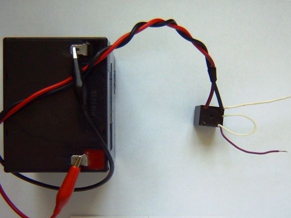
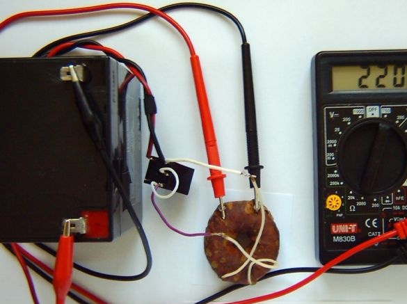
To understand how a constant but intermittent current works with a transformer, connect the primary winding of the transformer (where there are fewer turns) to the battery (12 V), and the secondary (where there are more turns) to the voltmeter.
Now, interrupting the power supply manually with one wire, we observe the appearance of a high voltage on the secondary winding (where there are more turns), it is fixed by a voltmeter.
Interestingly, the high voltage at the output of the secondary winding of the transformer will also be constant (a very small change in polarity), but intermittent (the "plus" and "minus" at the output do not change, but there is a constant voltage with interruption, which is set by the frequency of manual interruption of the contact):
Of course, holding the battery in your hands and constantly interrupting contacts is not the case. Everything should be automatic. Here you probably need to return to transistors, but no.
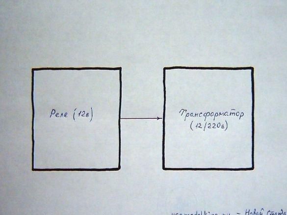
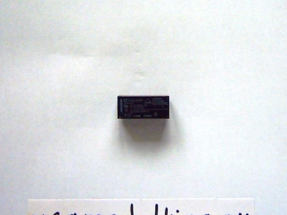
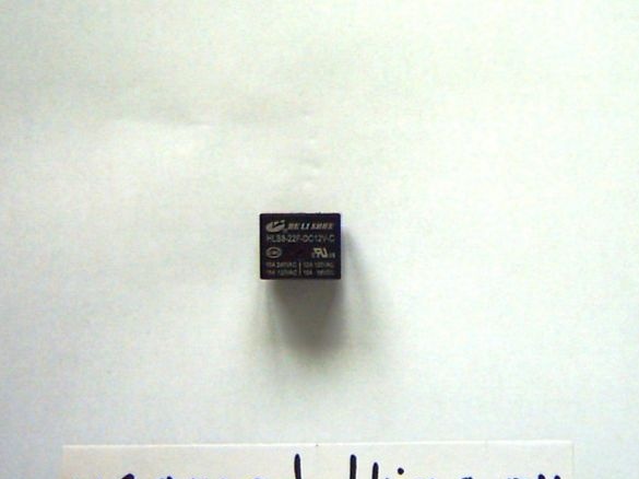
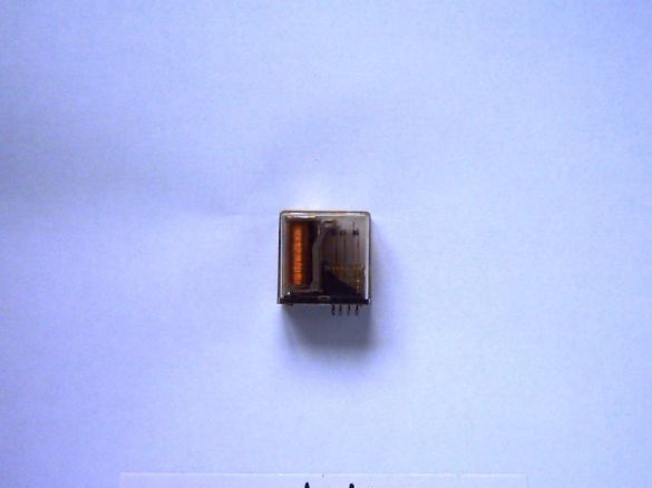
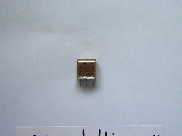
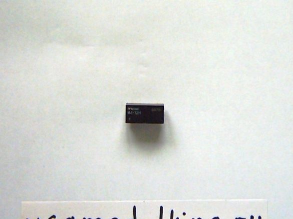
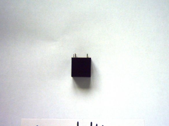
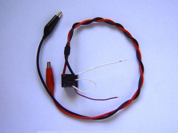
A relay will act as a switch, but the relay is not ordinary, but very ordinary, although the quality should be high.
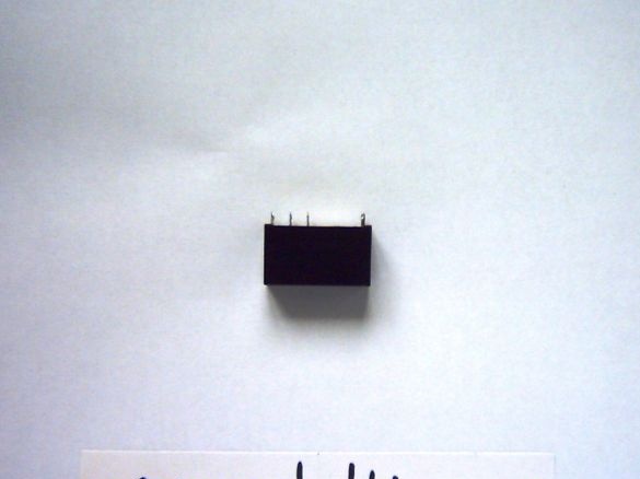
Relays are different:
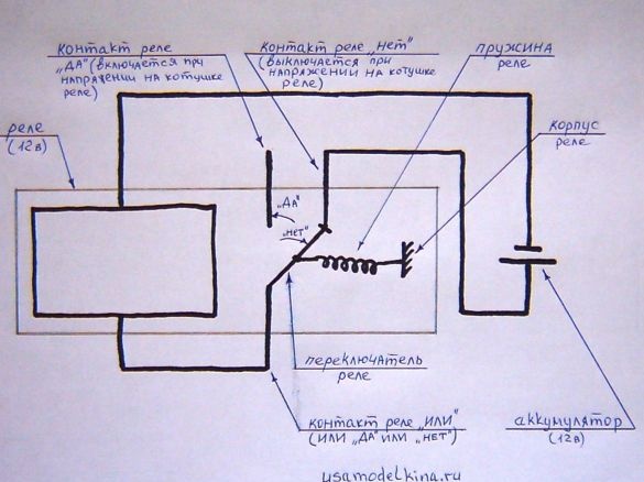
The fact is that each relay contains an iron rod, a winding on it and contacts that close or open, depending on whether there is voltage on the relay.
If there is no voltage on the relay, one contact closes (for example, "no"), when the voltage is turned on, the contact changes (for example, to "yes").
Relay contact reaction rate depends on many factors:
- current magnitude on the coil (coil resistance);
- voltage values;
- compression ratio of the spring;
- the gap between the iron core of the relay and the surface of the movable contact;
- contact arm length (the shorter the arm, the greater the relay response speed);
- the rate of core demagnetization in case of power failure;
- the density of the medium in which the moving part of the relay is located (for example, in a vacuum there is no air friction);
- temperature, etc.
Information about the factors of influence on the response speed of the relay and its regulation, necessary for the next step.
Namely, disassembling the relay operation scheme in the "continuous switching" mode:
With this connection of the relay, it literally "breaks off coils", this can not only be seen, but also heard. Why this happens is partially described above.
In short, the point here is the relay spring, when voltage is applied to the relay, it works, thereby opening its circuit, the spring returns the contact back to its place and the cycle continues again. For 1 s, depending on the quality factor of the spring (but not only the spring), there can be 100 or more closures and openings.
I noticed this relay feature almost by accident during my experiments.
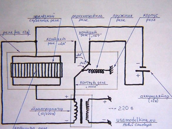
Accordingly, adding a transformer to the circuit, we obtain a generator and a voltage inverter:
We transfer the circuit to the experimental plane, for this you need:
Tools and devices:
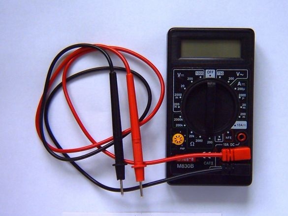
- a multimeter (we measure the voltage, it is better to use a pointer voltmeter, since digital ones sometimes can not record intermittent voltage);
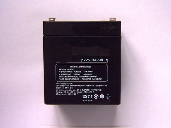
- battery (12 V);
- soldering iron;
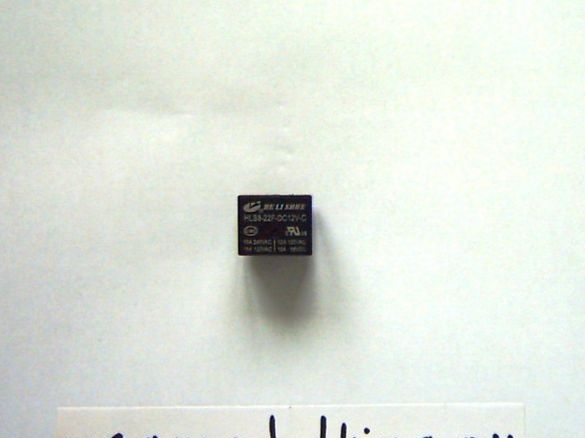
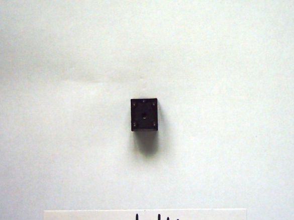
- relay (for 12 v);
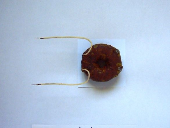
- transformer (from 12 to 220 V, 10 W);
- lamp (220 V, 1 W);
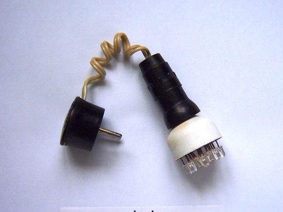
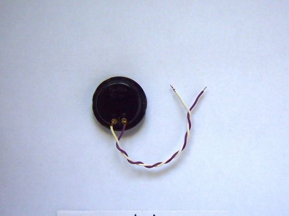
- headphone (at 50 ohms).
Expendable materials:
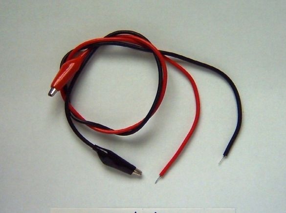
- wires;
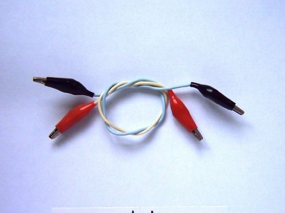
- "crocodiles" (4 pcs.);
- solder;
- rosin.
Stage 1.
We connect the relay to the battery according to the scheme, we immediately hear the relay:
Stage 2.
We connect the transformer to the relay and fix the high voltage at the output (sometimes it is better to use a pointer voltmeter):
Stage 3.
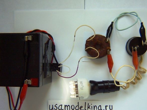
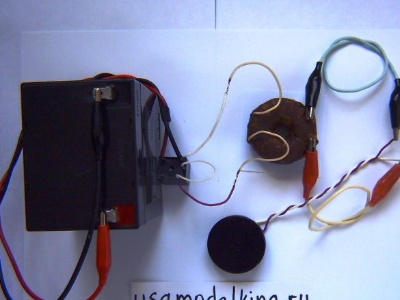
At the output of the transformer, we install a lamp for 220 V, low power, it lights (and does not light at 12 V):
Stage 4.
If you connect a head phone instead of a lamp (it works with or without a transformer), then a sound will be emitted from there, something like a siren:
So the circuit works, producing a pleasant buzz. Unlike a transistor inverter, my relay inverter circuit contains less parts. I didn’t measure the efficiency, well, approximately 65% (taking into account the efficiency of the transformer).
In the next article - a continuation of this, I will consider more practical, advanced and powerful inverter circuits without transistors.
Video:


