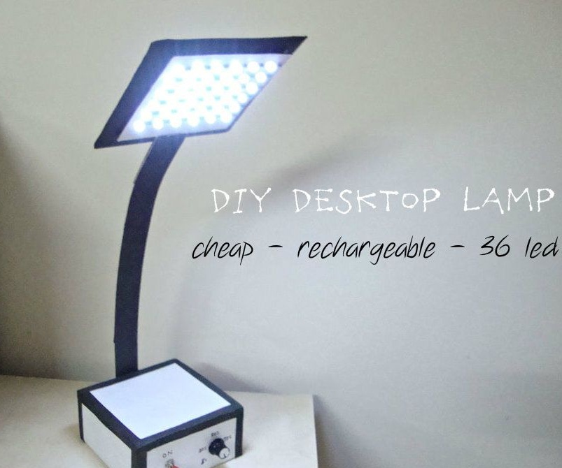
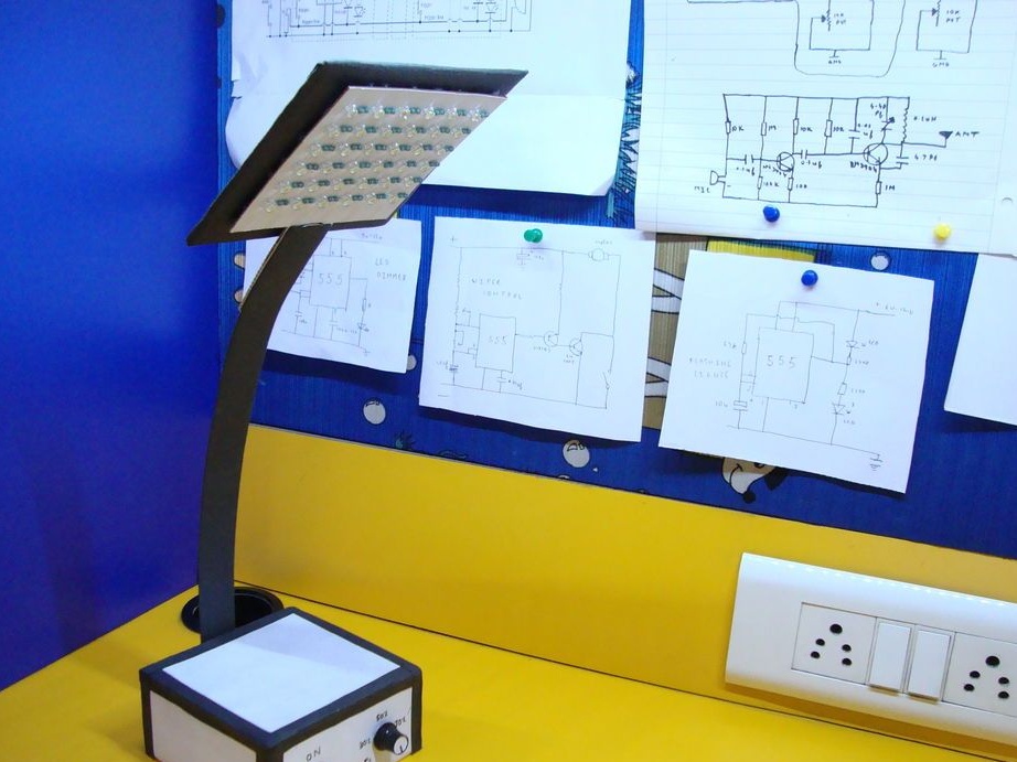
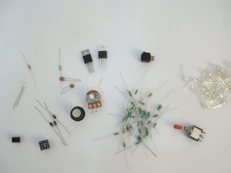
The lamp that the Master introduced to us has 36 LEDs. The luminaire is powered by two 4V lead-acid batteries. The batteries are being charged from the mains. Also in the lamp there is an adjustment of the brightness of the light. For the manufacture of the lamp, the master used the following
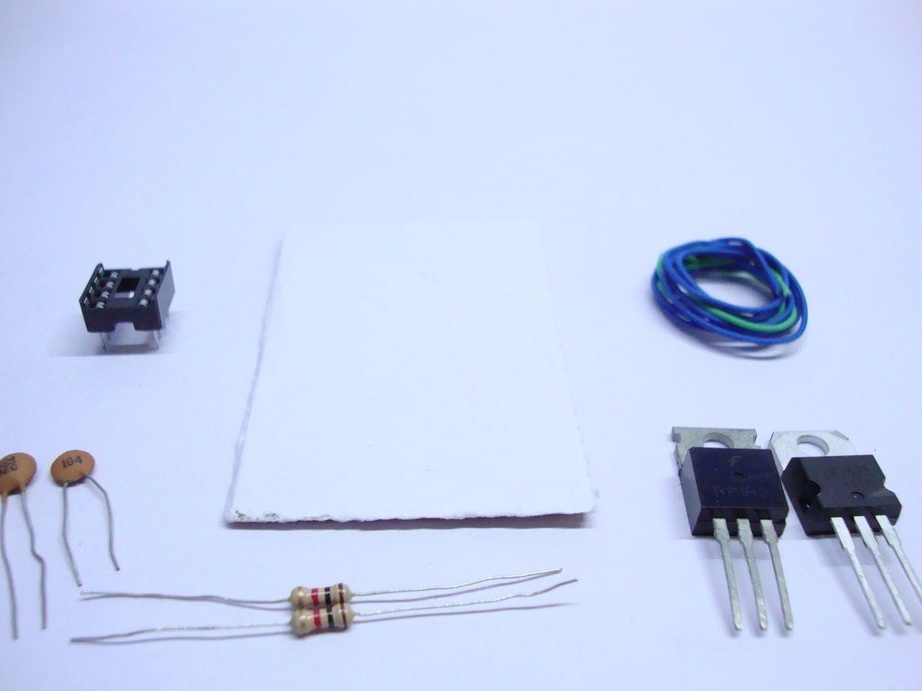
Materials and tools:
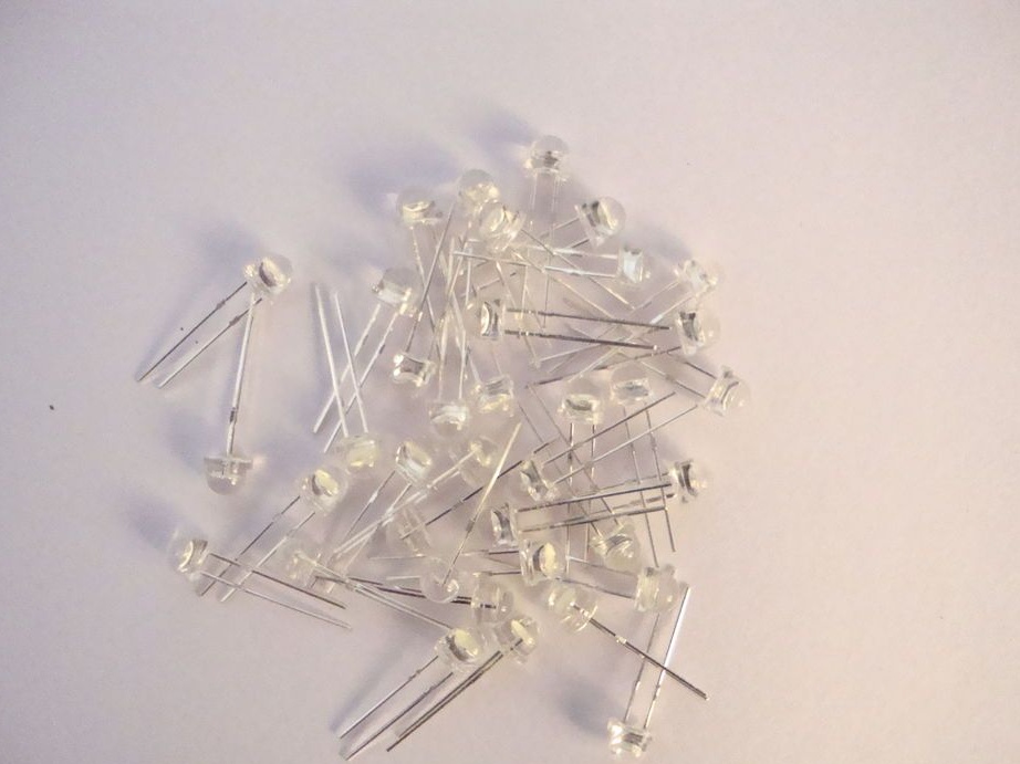
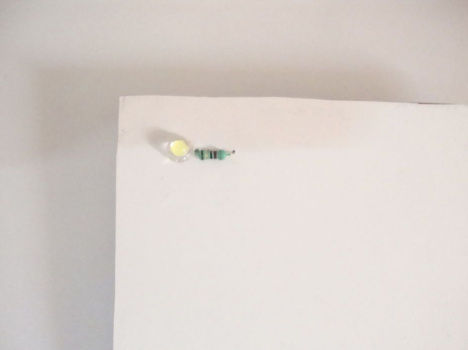
-White LEDs - 36 pcs.;
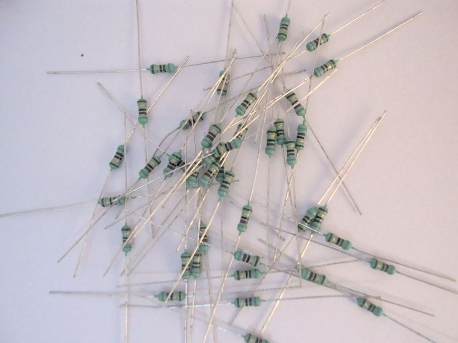
- Resistors 82 Ohm - 36 pcs.;
- AKB 4V 1.5 Ah -2 pcs.;
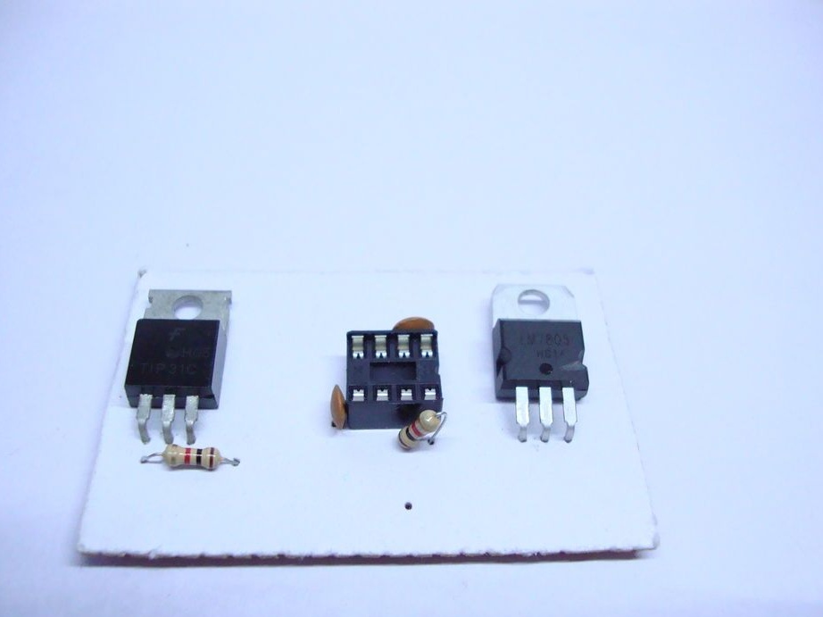
- Voltage regulator 7805 - 1 pc.;
- Toggle switch - 1 pc.;
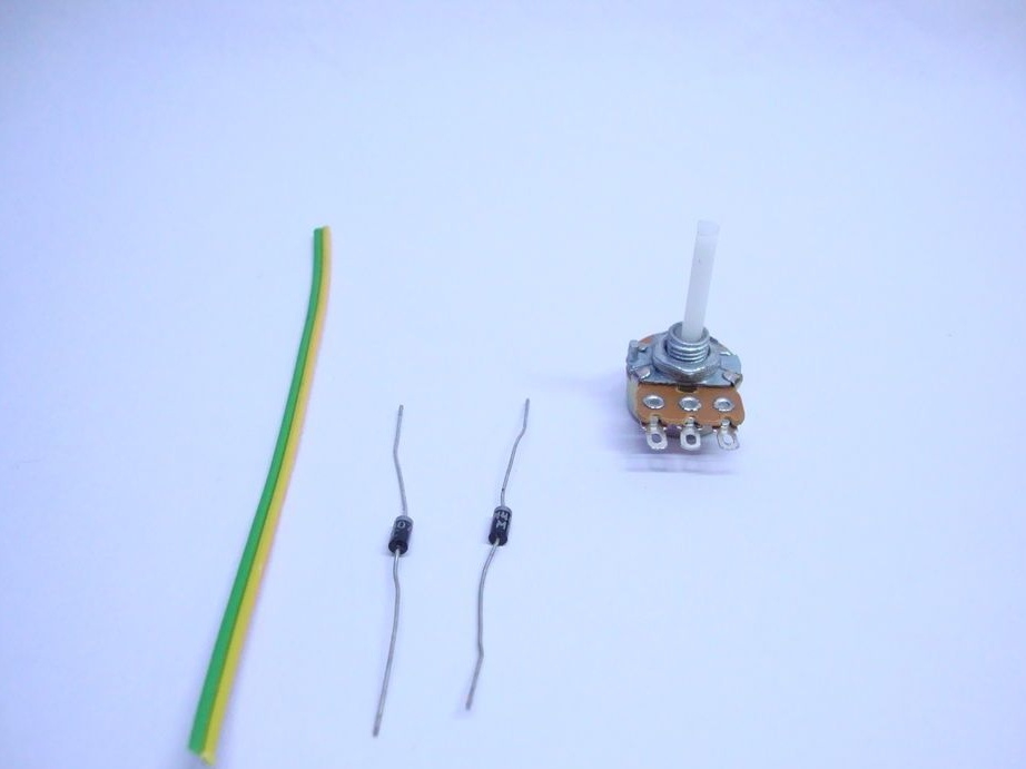
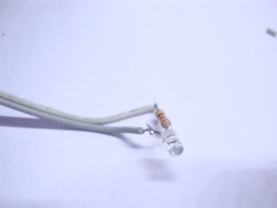
- Red or green LED - 1 pc;
-3.5 mm jack - 1 pc.;
- Potentiometer 50 kOhm - 1 pc.;
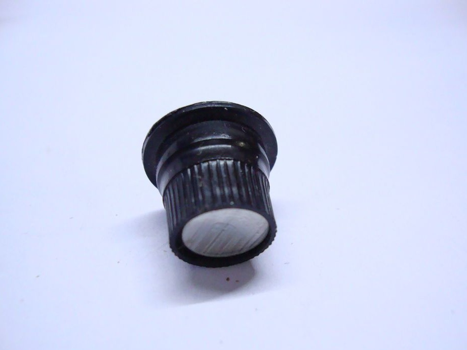
- Handle for potentiometer - 1 pc.;
- Chip 555 - 1 pc.;
- Diode 1N4001 - 2 pcs;
8 pin DIP IC
- Resistors 1 kOhm - 2 pcs.;
- Resistor 330 Ohm - 1 pc.;
- Ceramic capacitors 0.1 microfarads - 2 pcs.;
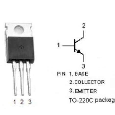
- Transistor TIP31C - 1 pc.;
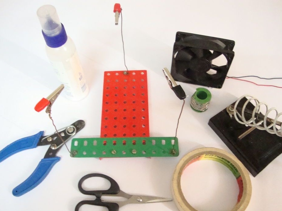
-Color wires;
-Soldering iron;
-Solder;
-Nippers;
-Scissors;
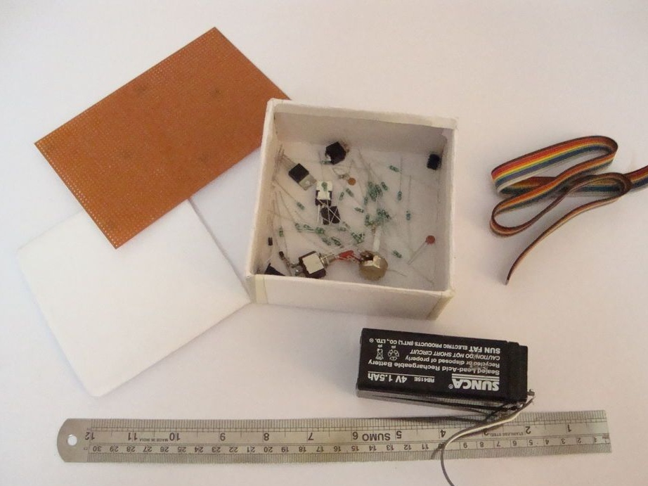
-Cardboard box;
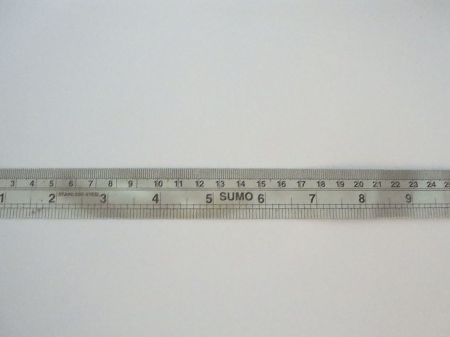
-Metal 30 cm ruler;
-White and black paper;
-Glue;
-Circuit board;
-Bread board;
-Double sided tape;
-Needle;
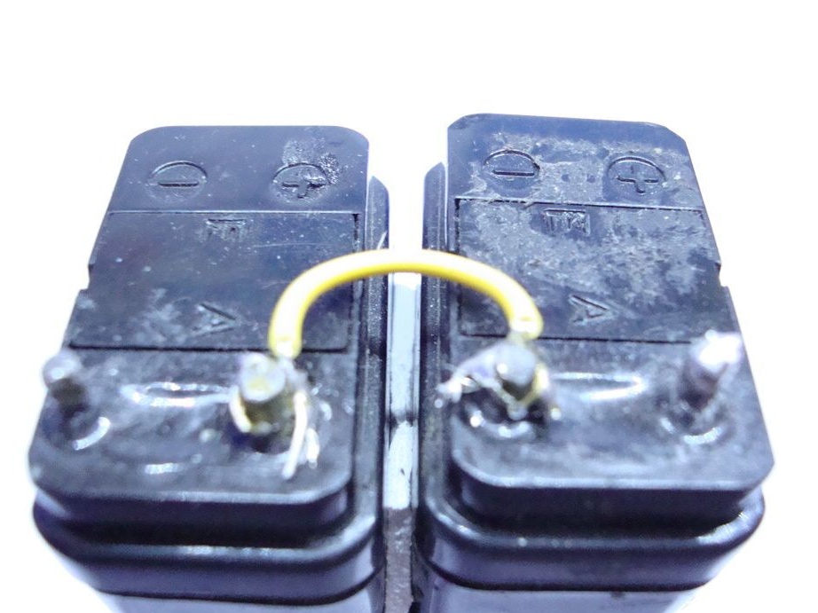
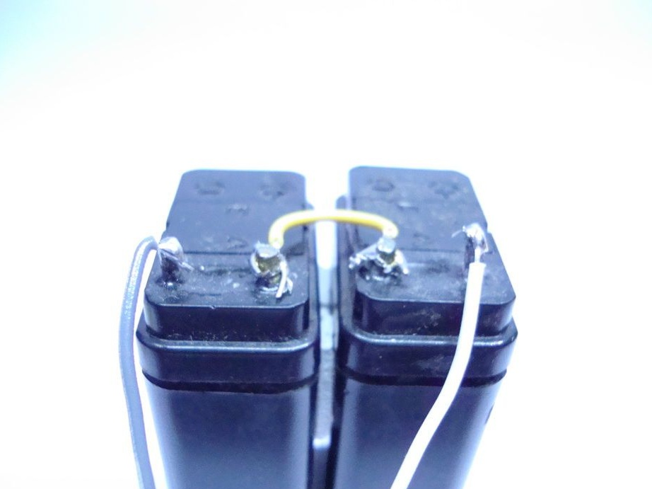
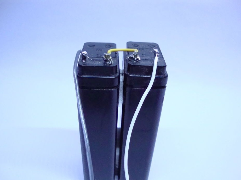
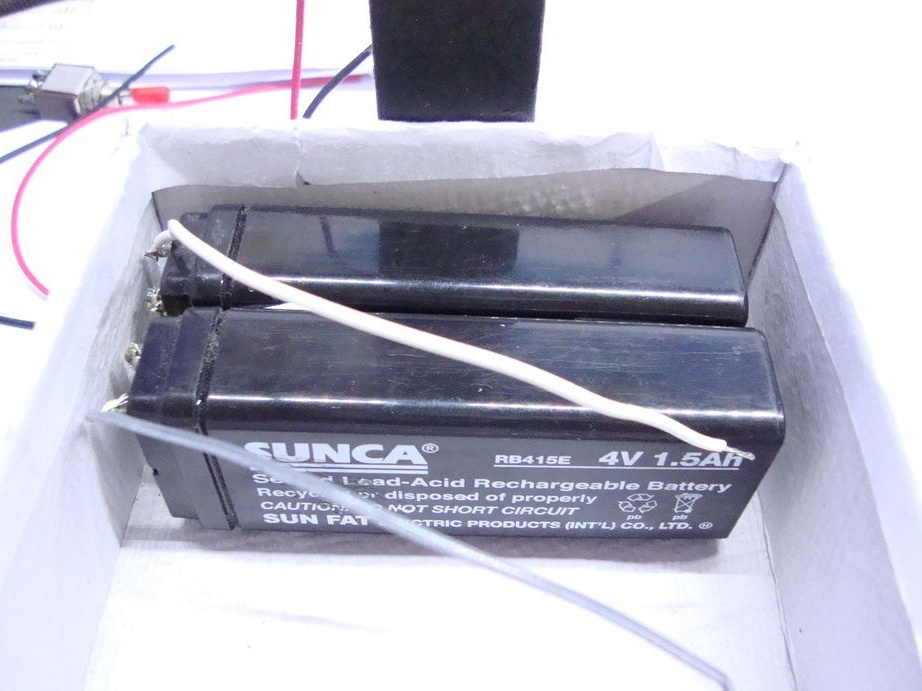
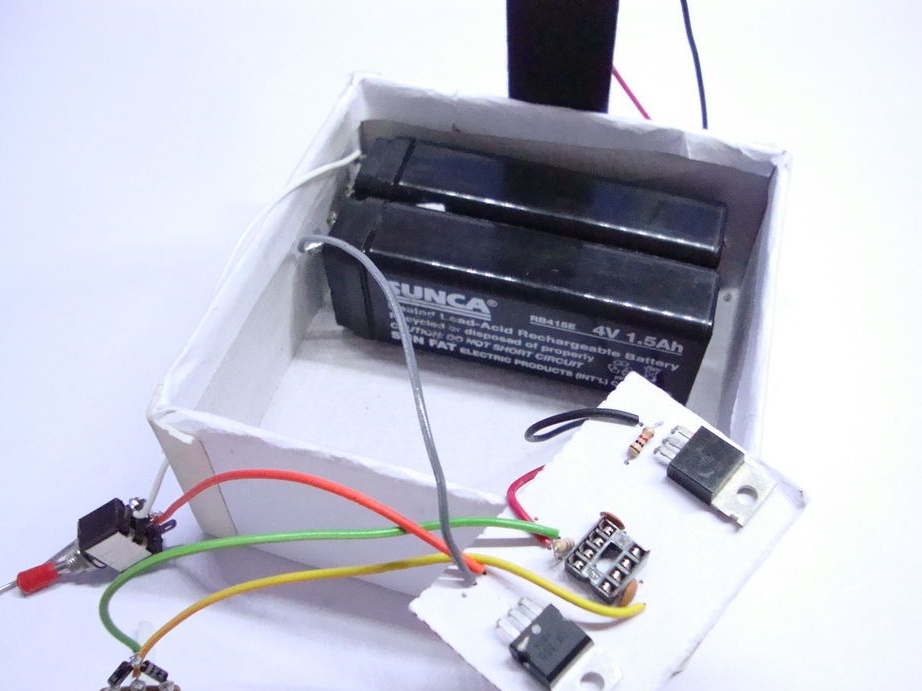
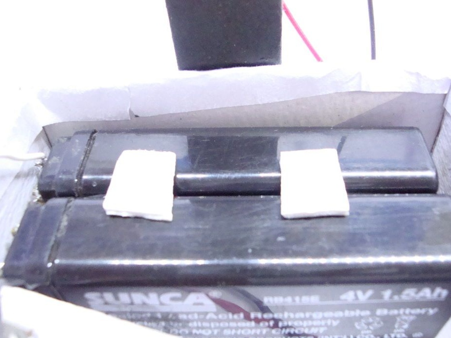
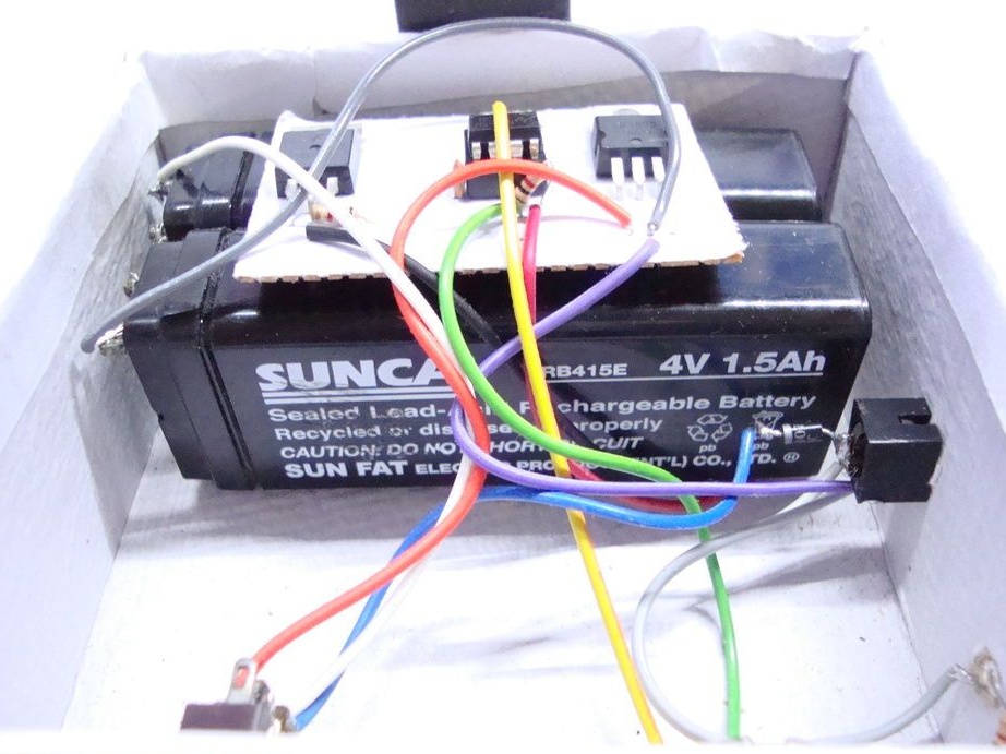
Step One: Batteries
To power the lamp, the master uses two lead-acid 4V batteries. Connects batteries in series. The wires are soldered to the second terminals of the battery. The battery will be attached to a double-sided tape.
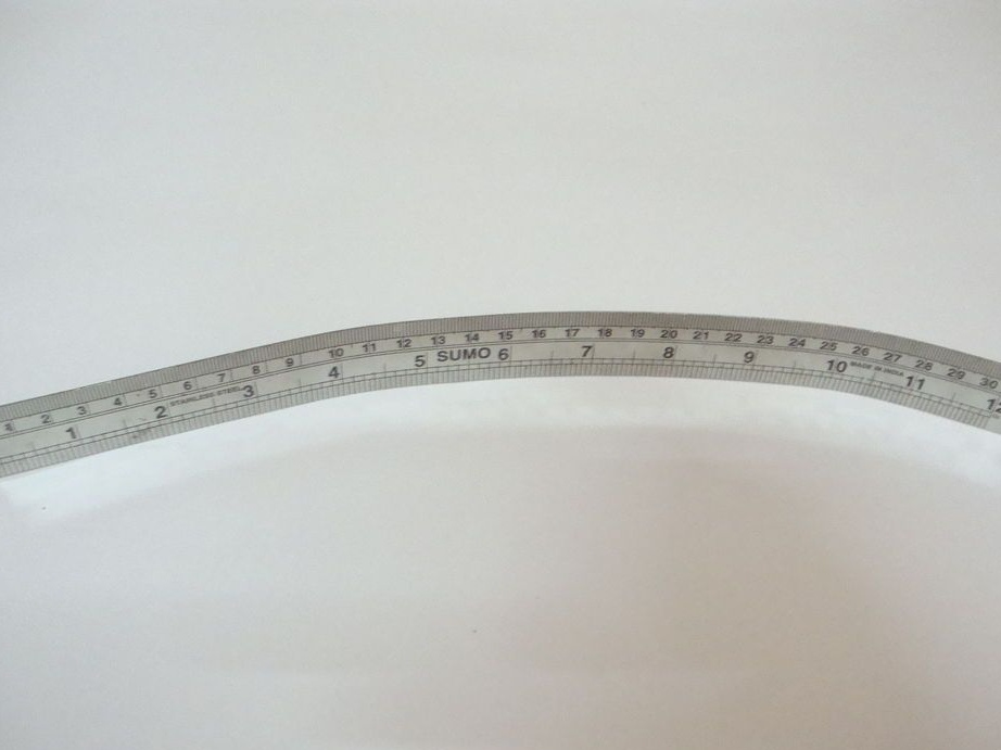
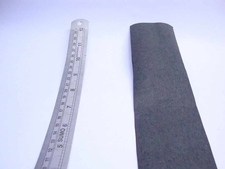
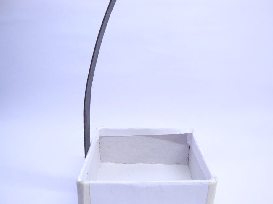
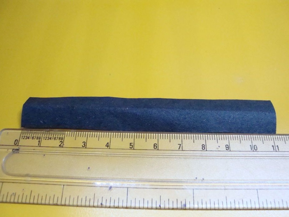
Step Two: Stand
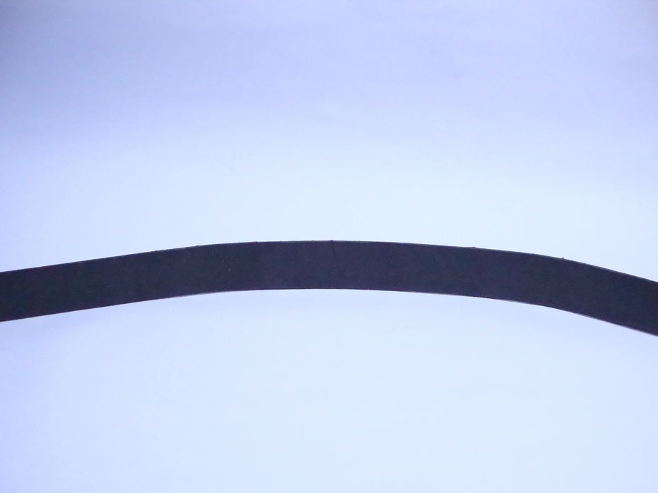
The master made a rack from a ruler. Curves a metal ruler with an arc. Wraps it over with black paper.
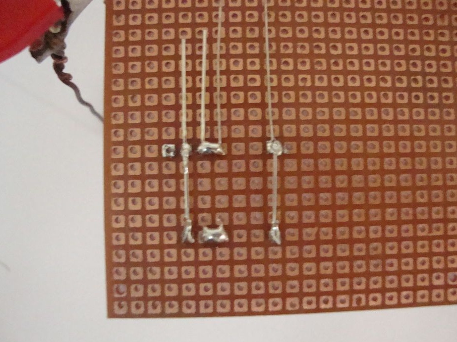
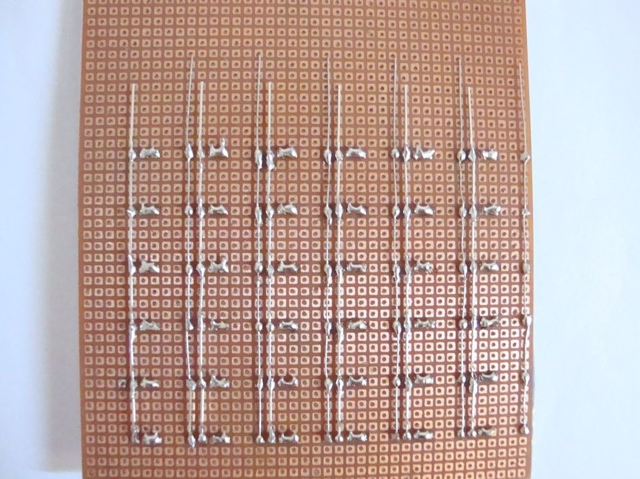
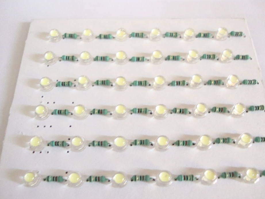
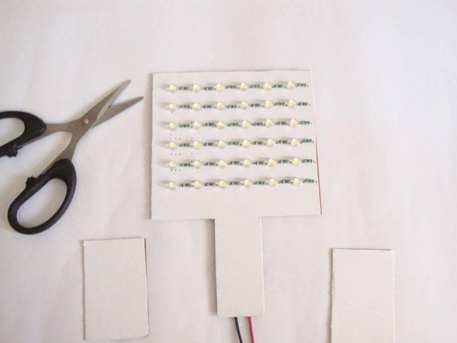
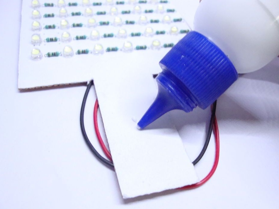
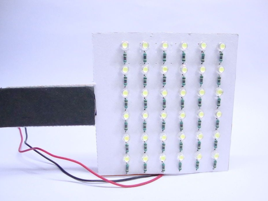
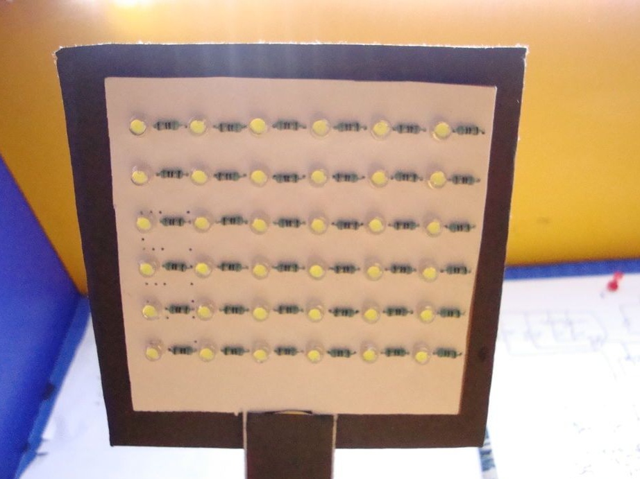
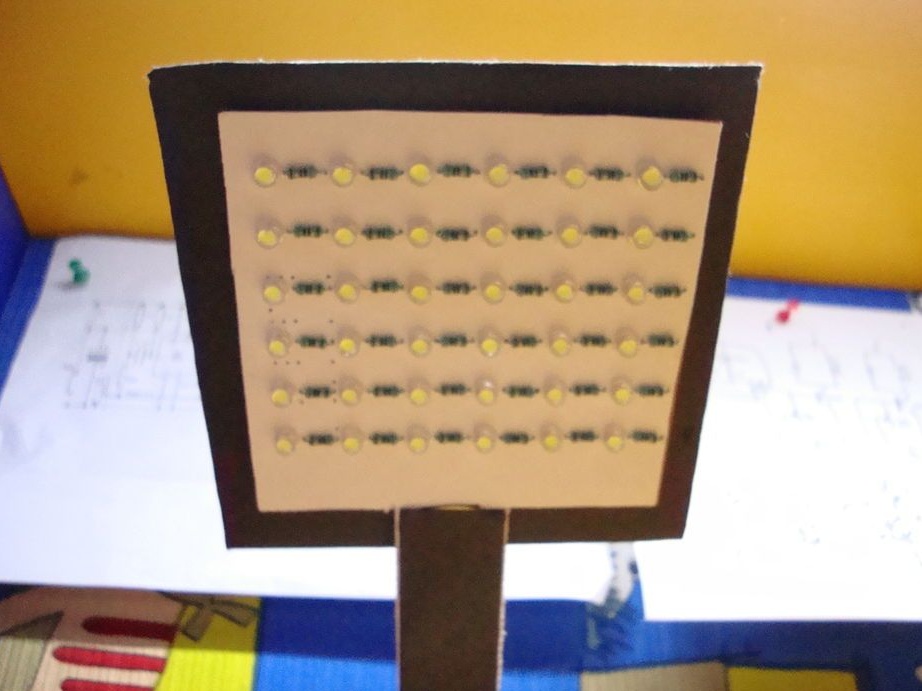
Step Three: LEDs
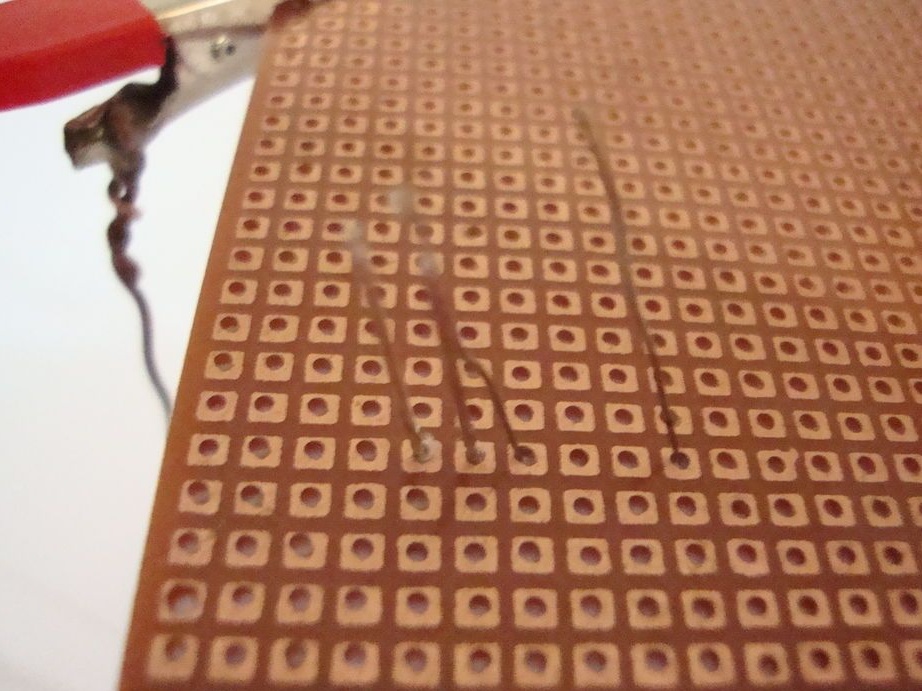
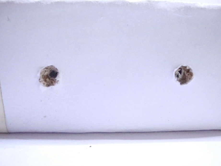
Pastes the breadboard with white paper. A needle pierces holes in the paper.
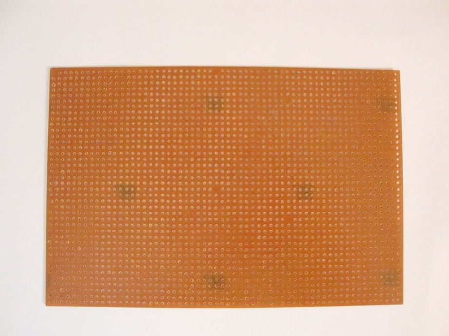
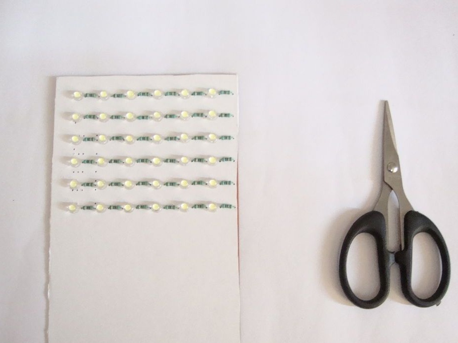
Mounts the LEDs on the board. Together with LEDs, it mounts resistors.
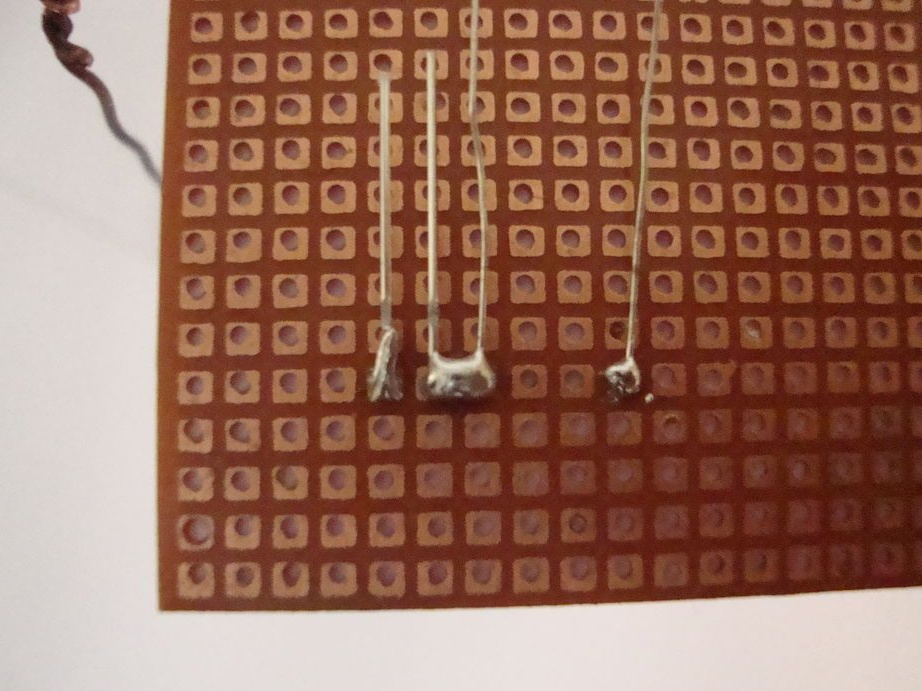
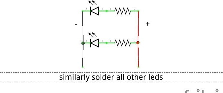
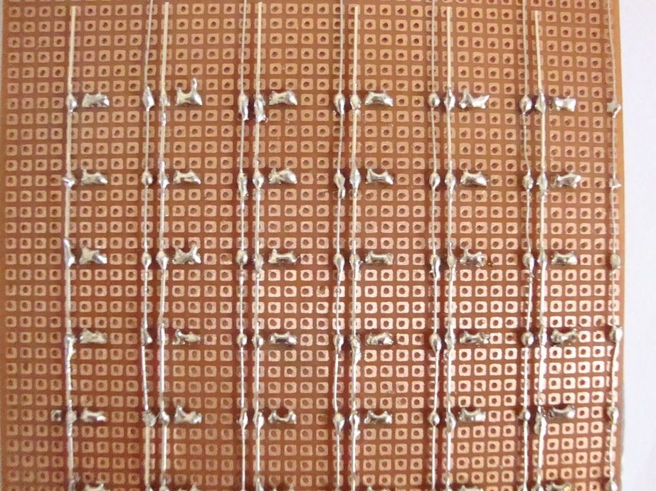
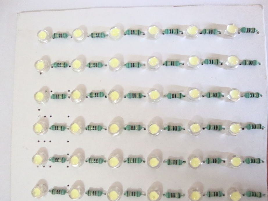
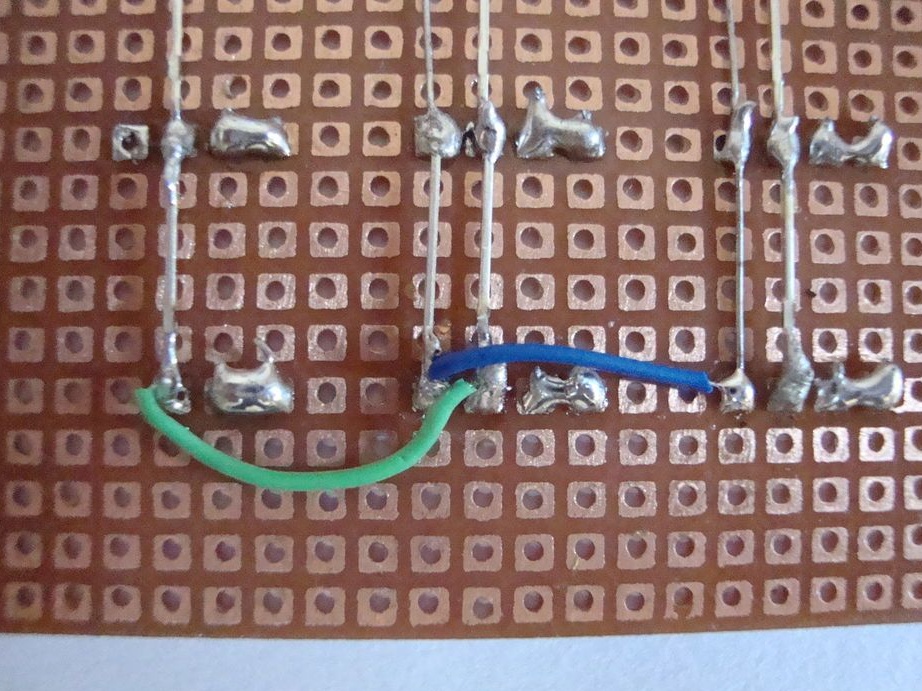
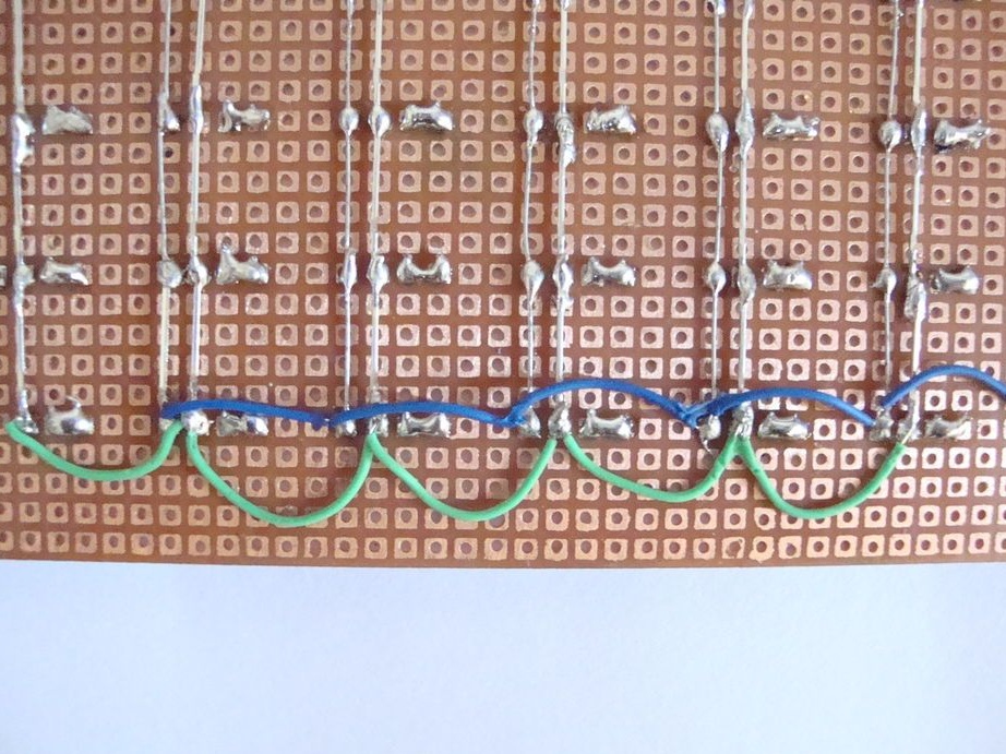
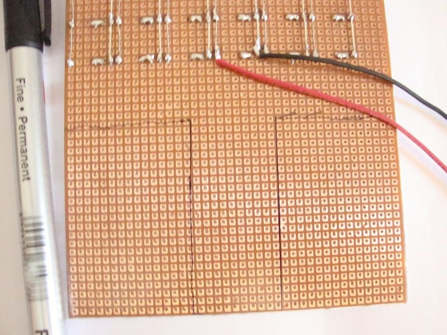
After mounting six LED tracks, connects them in parallel.
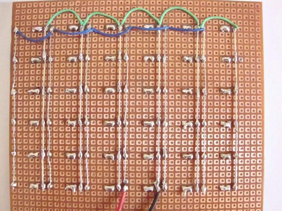
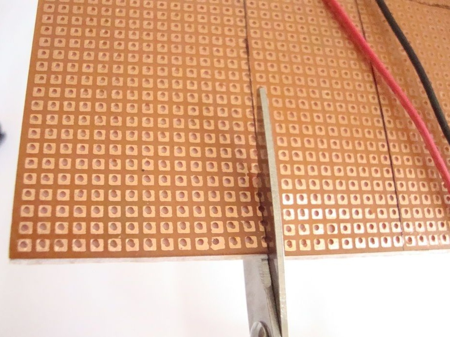
Cuts the board as in the photo.
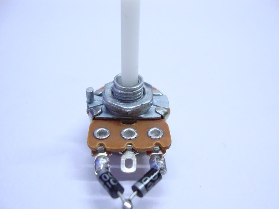
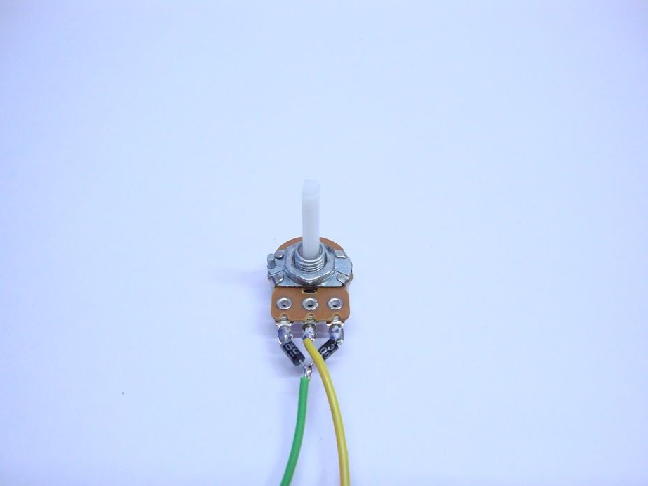
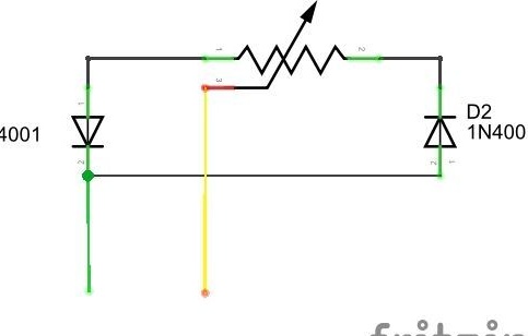
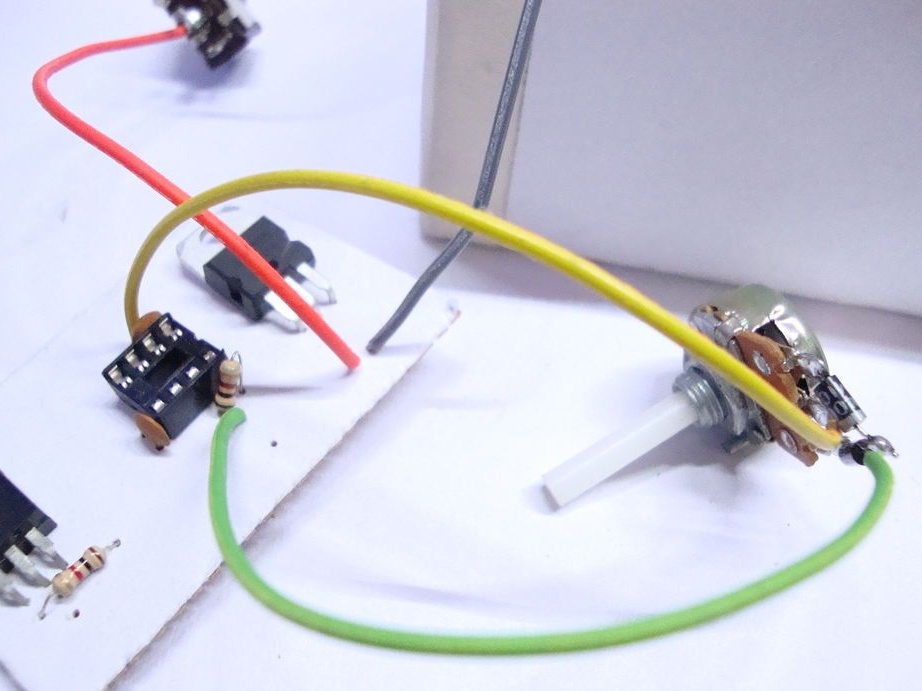
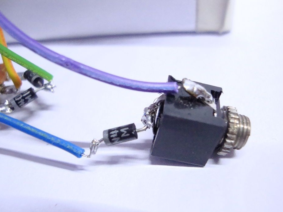
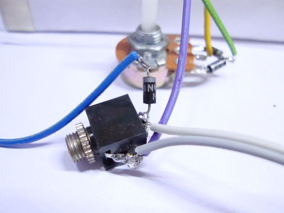
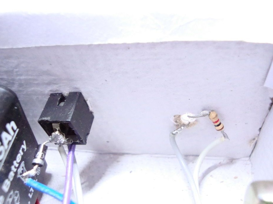
Step Four: Potentiometer
According to the scheme, the diodes are soldered to the extreme contacts of the potentiometer. Then solder the second ends of the diodes and solder the wire to them. A wire is soldered to the middle pin.
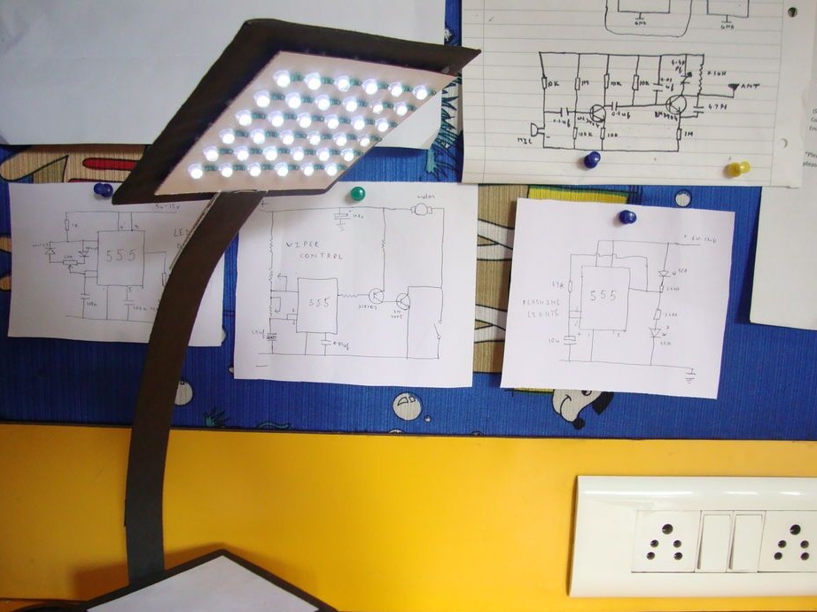
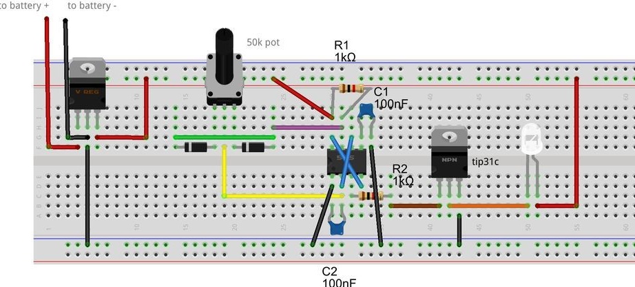
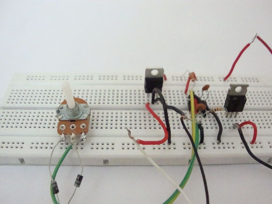
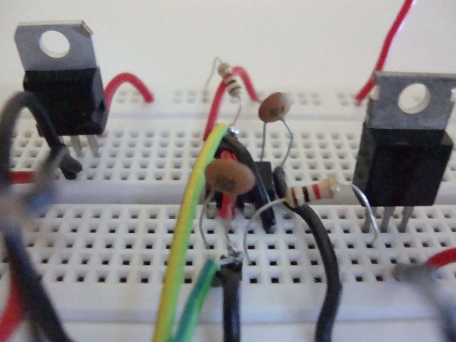
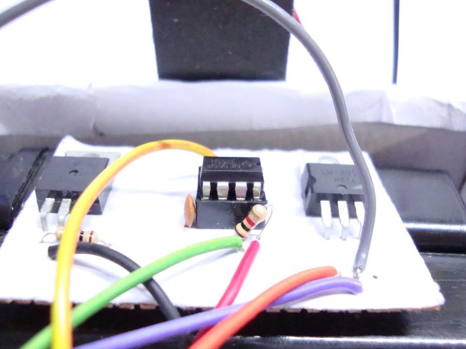
Step Five: Breadboard
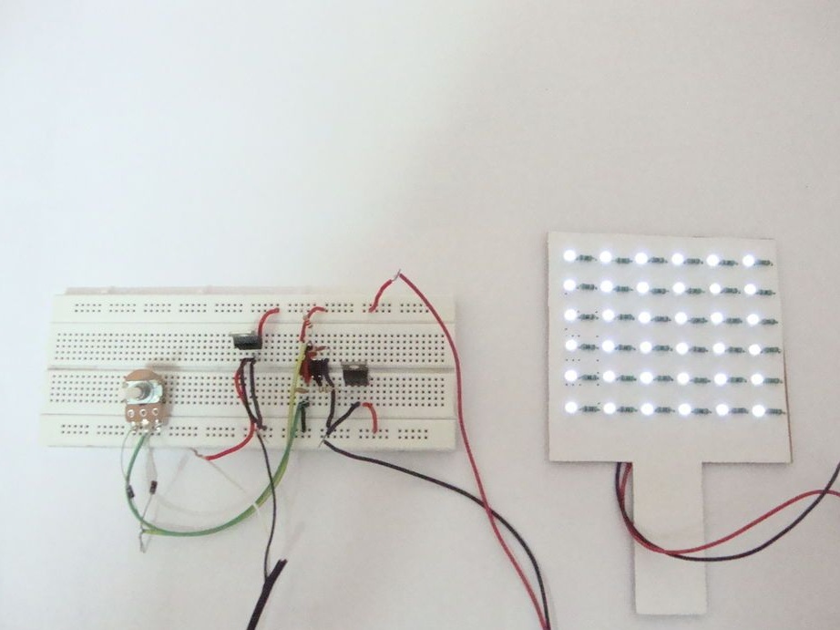
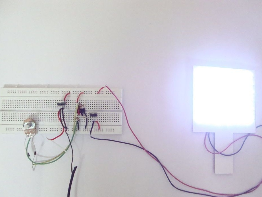
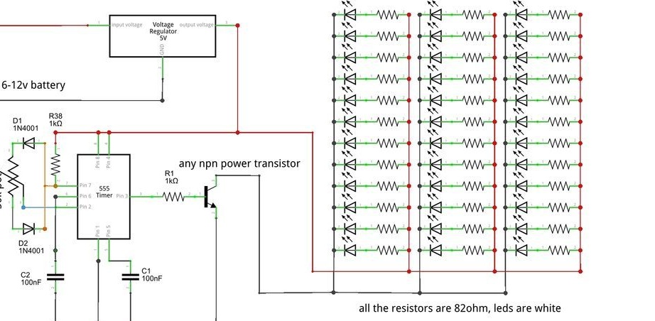
Before soldering the control unit, the wizard checks the operation of the electronics on the breadboard. The breadboard allows you to assemble the circuit without soldering using wires. The scheme is given below. The photo also shows the glow of the lamp at 5% and 95% brightness.
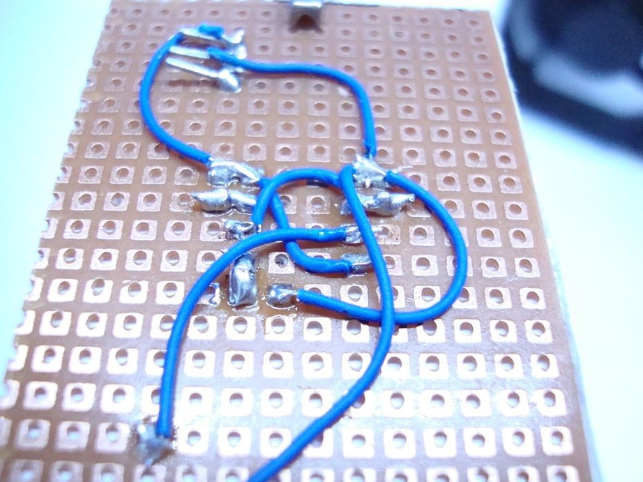
Step Six: Dimmer
Dimmer is— electronic a device designed to change electrical power (power regulator). In this case, using a dimmer, the brightness of the light will be adjusted.
According to the scheme collects a dimmer.
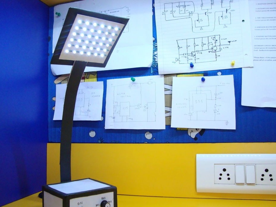
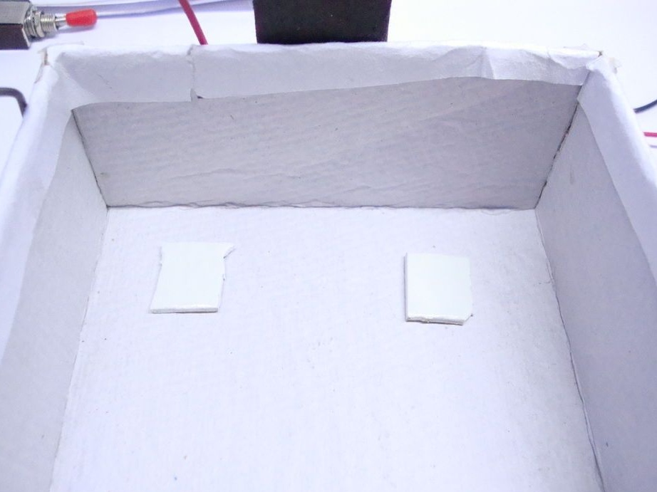
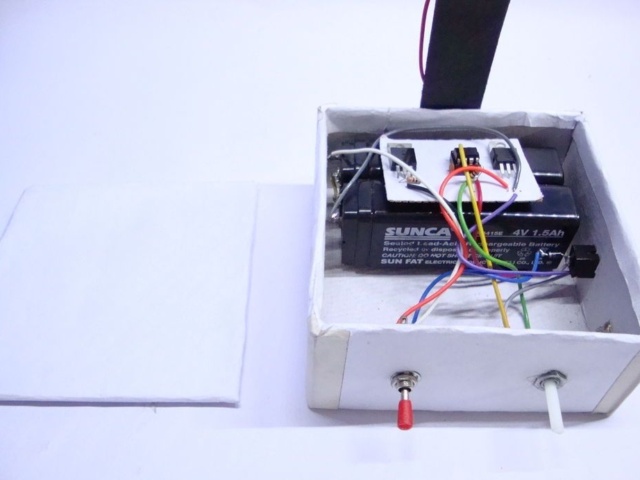
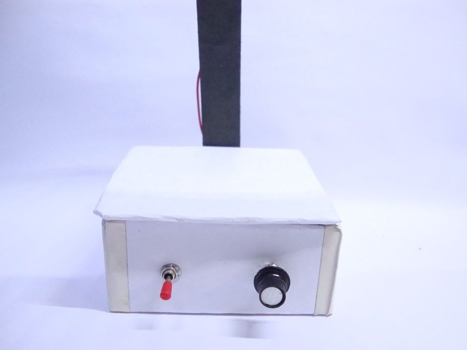
Seventh step: lamp assembly
Sticks a rack to the box.
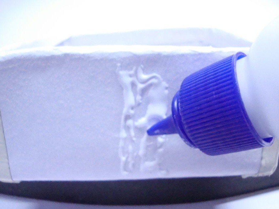
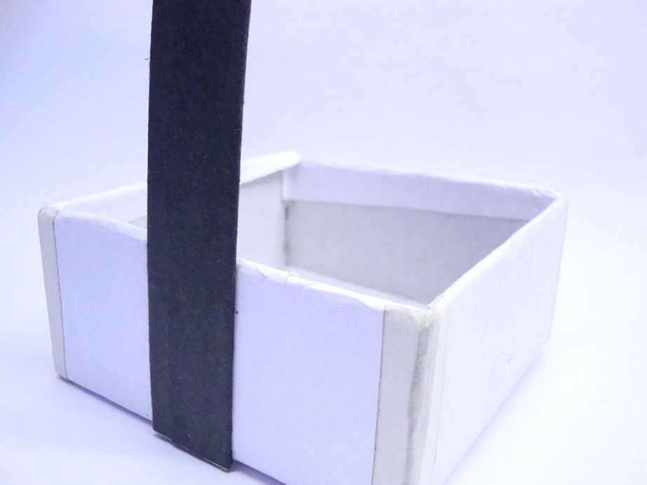
Glues the lamp to the stand.
Double-sided tape secures the batteries inside the box.
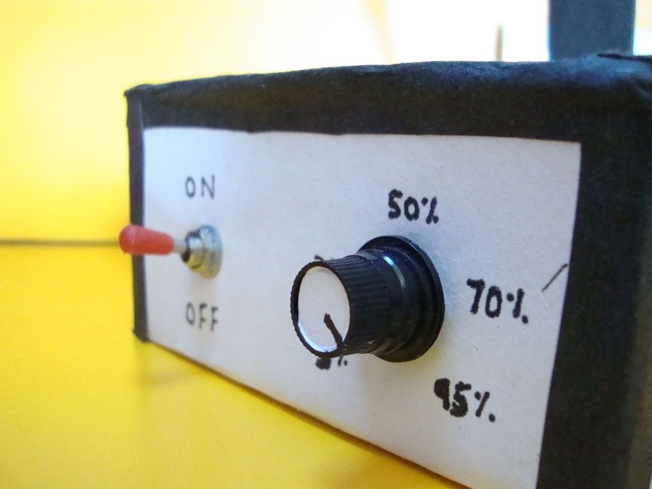
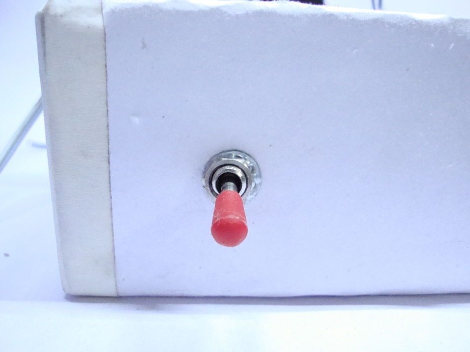
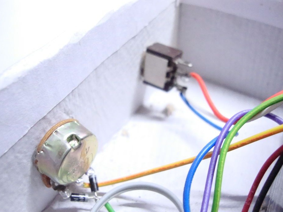
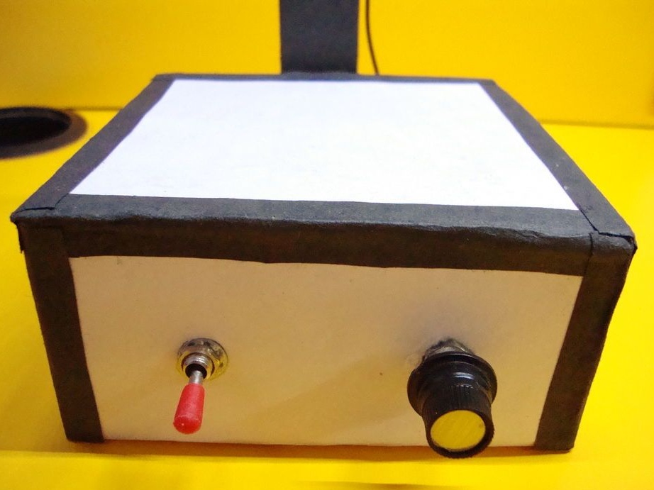
Adds a toggle switch.

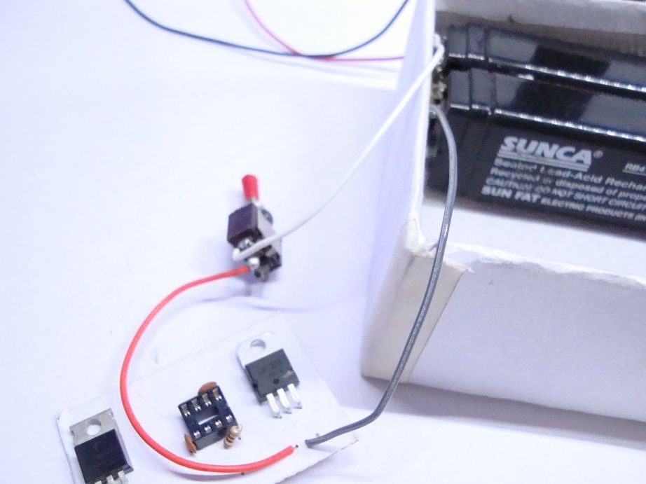
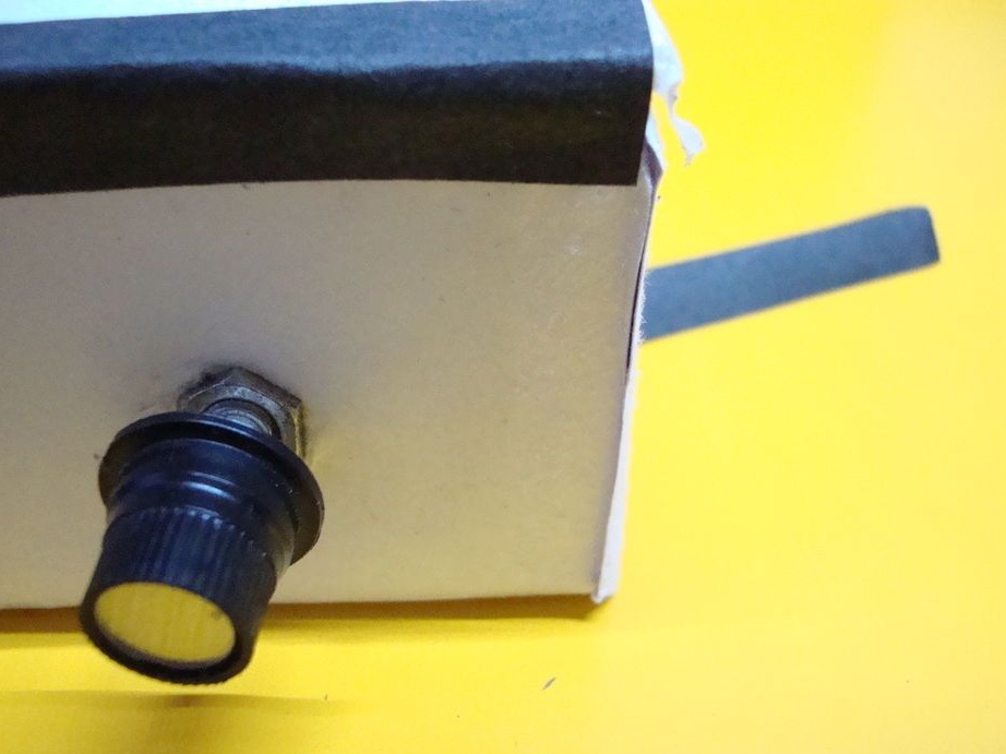
Solder potentiometer.
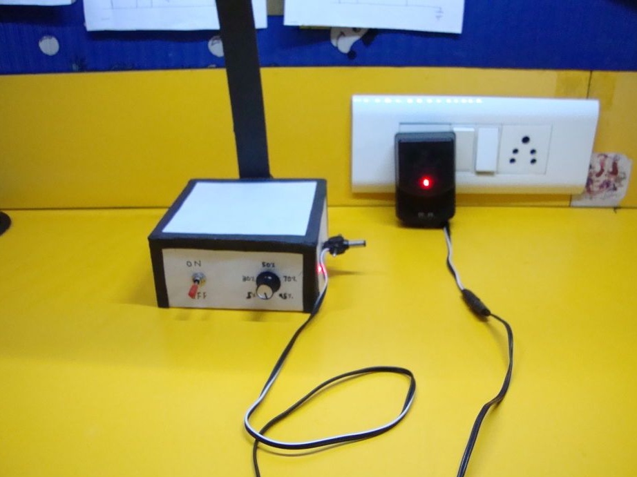
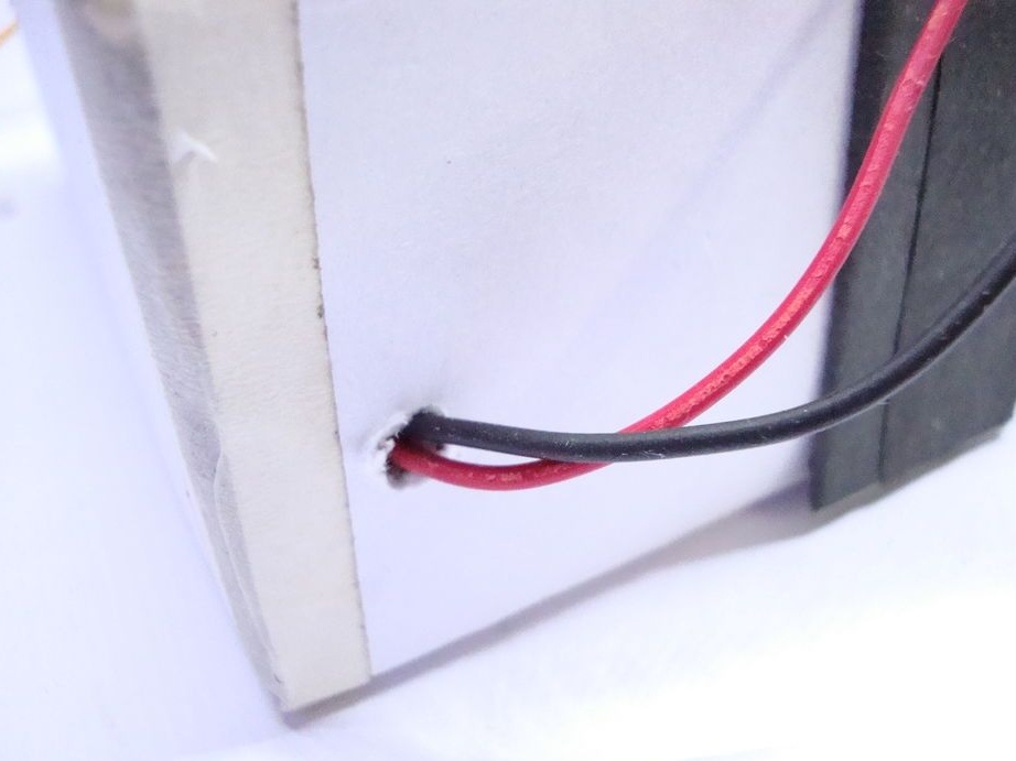
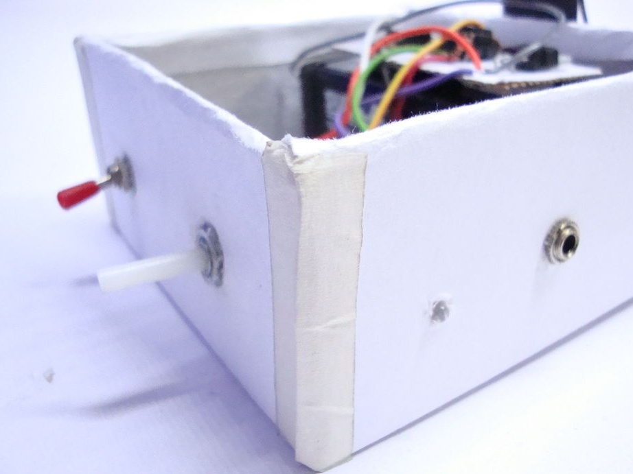
Makes a hole in the box. Extends the wire from the lamp into the hole. Solder the wires according to the scheme.
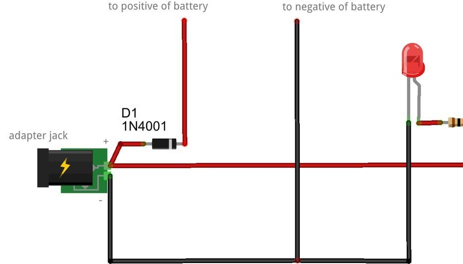
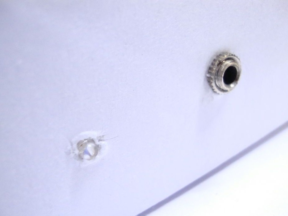
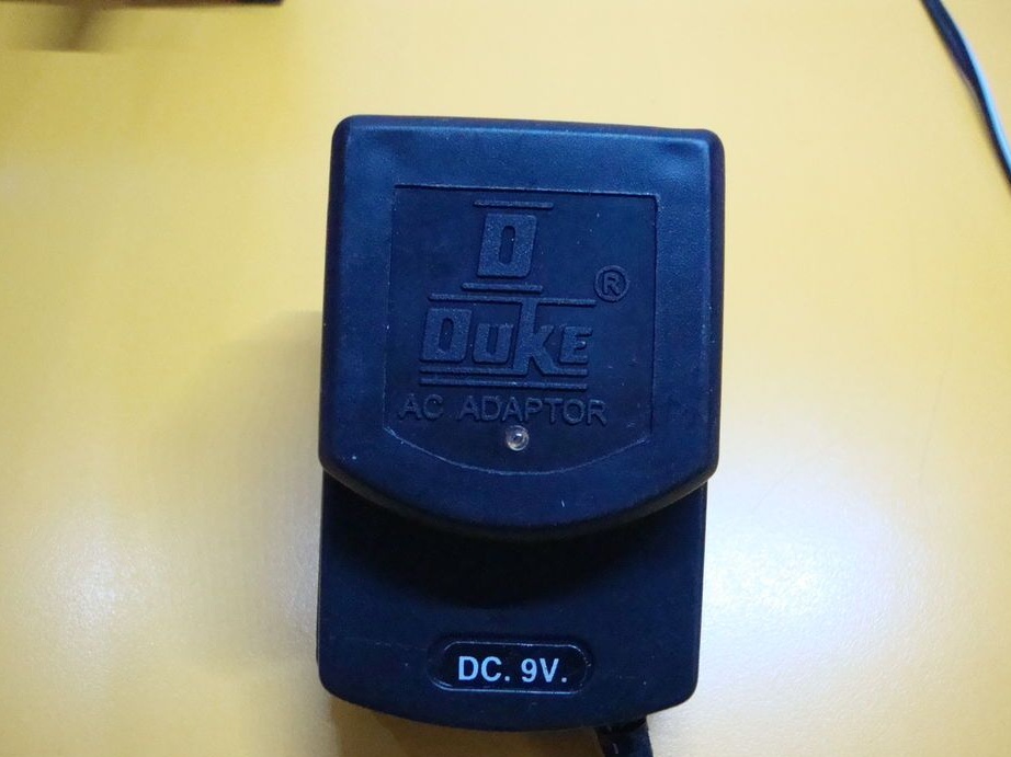
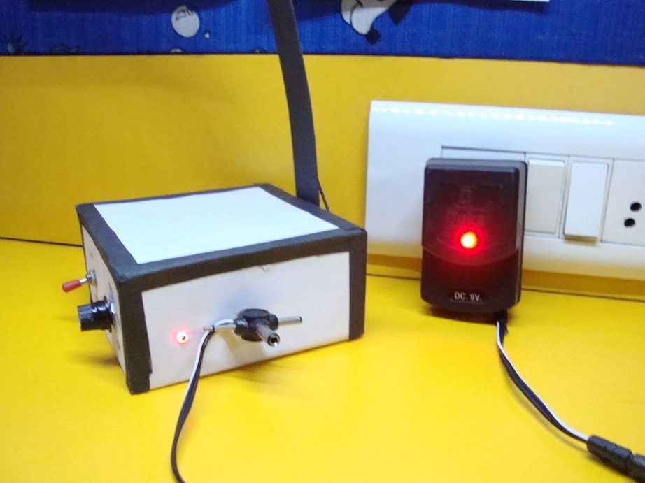
According to the scheme, mounts the charging socket. The LED will light when the batteries are charging.
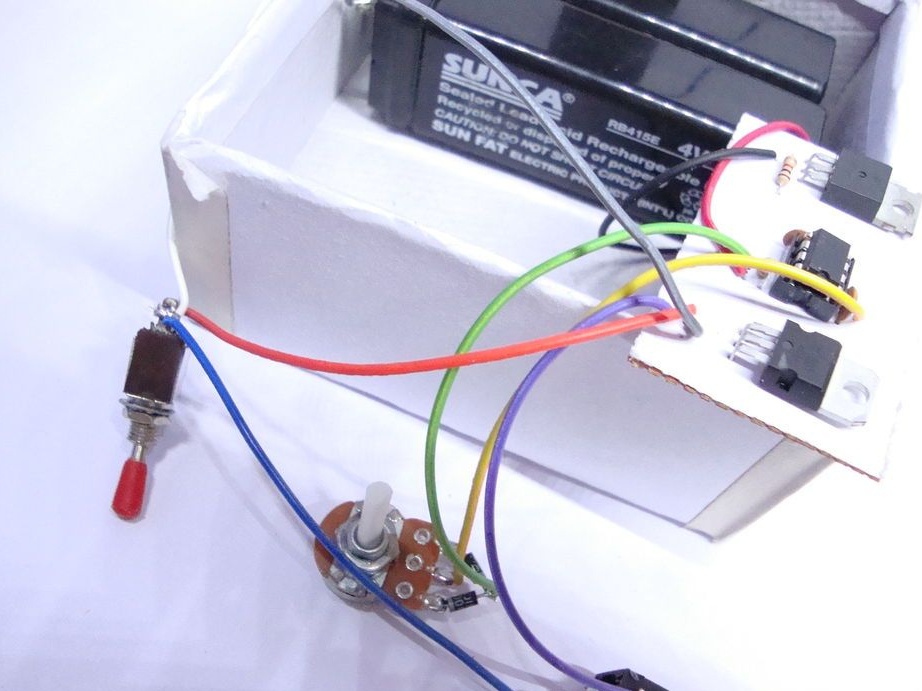
Secures the board.
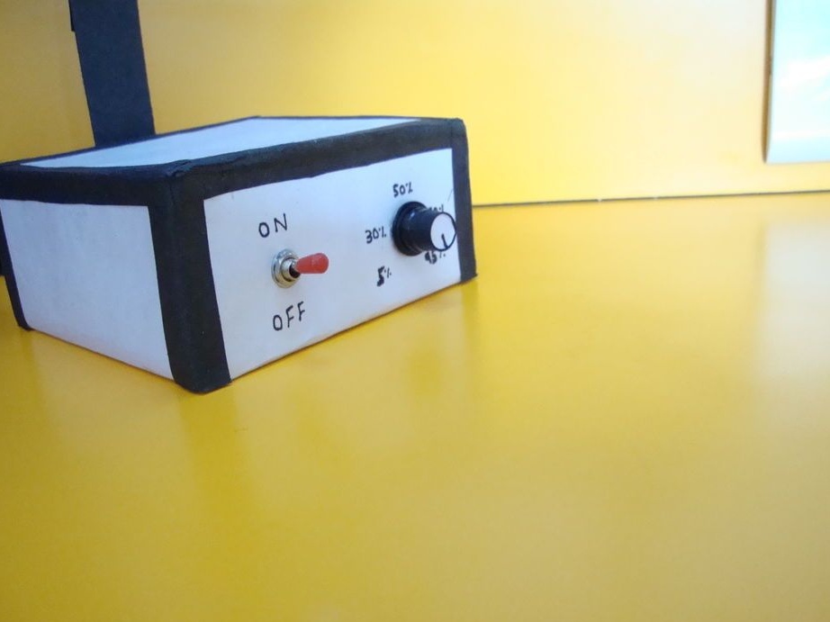
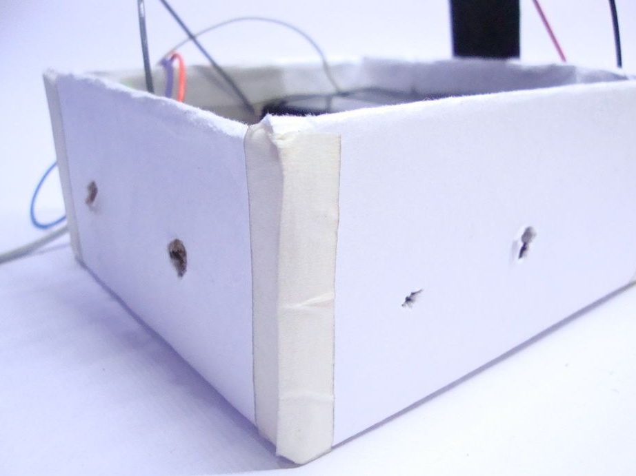
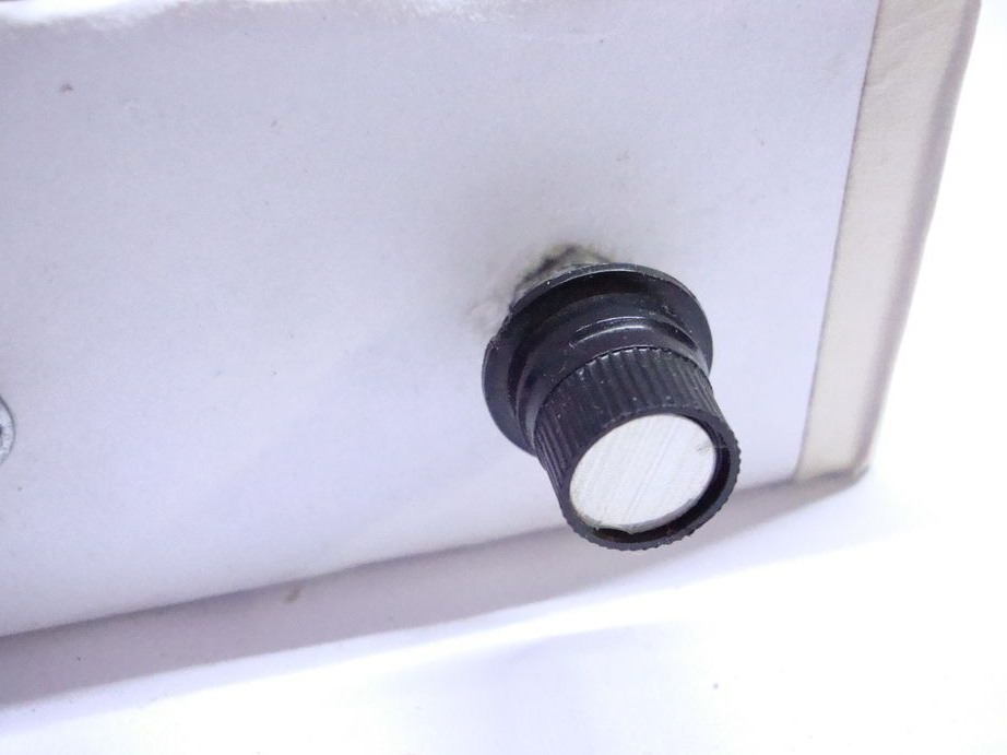
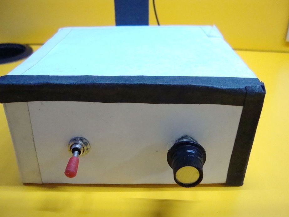
The box makes four holes. Sets the potentiometer, charging socket, LED and toggle switch.
Closes the box with a lid.
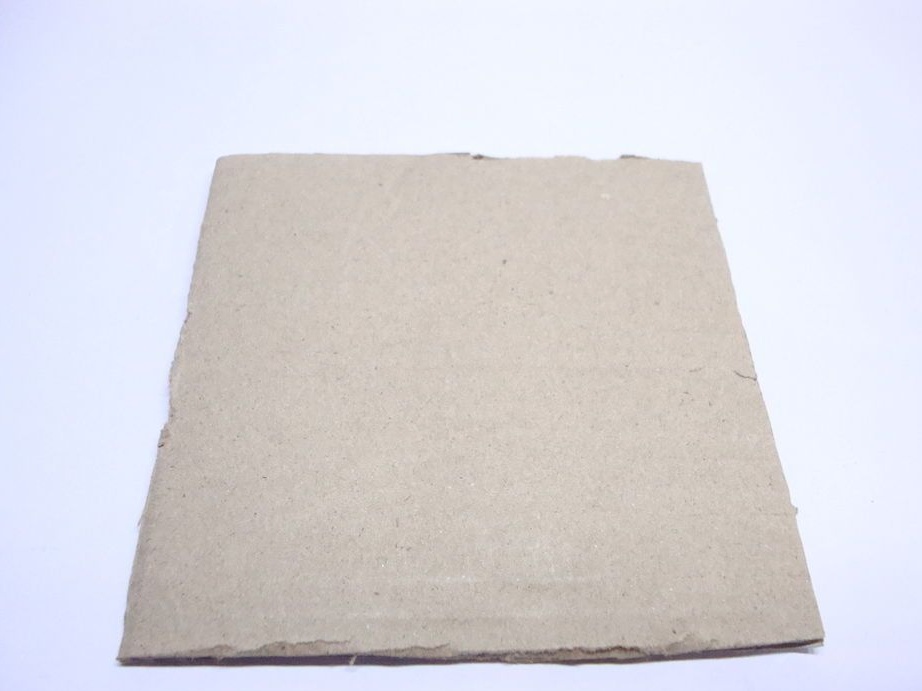
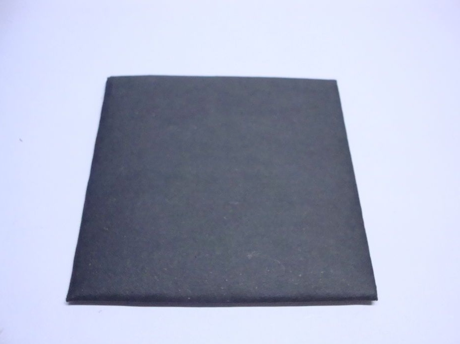
Cut a rectangular piece of cardboard. Tape over it with black paper. Glue cardboard to the back of the lamp.
Makes a border on the box.
The lamp is ready. It remains only to charge the batteries.
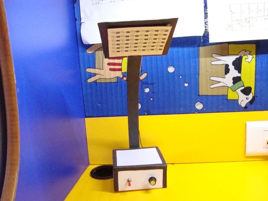
The lamp that the master assembled turned out to be inexpensive and easy to manufacture. If you wish, you can make the case more beautiful, but the master wanted to make a lamp with a minimum of cost. By reducing the number of LEDs, you can increase the life of the lamp without charge, and by increasing their number, you can add brightness.