
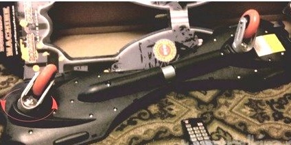
The background is as follows: for the pleasure of overcoming physical inactivity, the Rollersurf board was purchased. Since there are only two wheels on the board, riding on it requires a sense of balance, you can “stand” on it only in motion. After making sure that after continuous movement at a distance of about 700 meters, the wheels seemed to get stuck in the sand and the movement was very difficult, I turned to the Internet and specialists. It became clear that due to the excessive softness of the wheel material for my weight, the wheel material is very hot and softened, contact with the road increases and the increased viscosity of the wheel makes it difficult to control and create torque. After replacing the wheels with a harder roll, the boards increased significantly, as did the ease of operation. On the same long track, the familiar braking did not happen, the speed continued to increase, which led to an unpleasant drop.
The idea to measure speed and limit yourself in acceleration came, probably after a fall :) There was a prototype from 2014, where such a device was created, but for a different type of board, where the plane of rotation of the wheel does not move much relative to the board and electronics can be placed on the board itself by connecting it to the sensor on the wheel with a flexible wire.
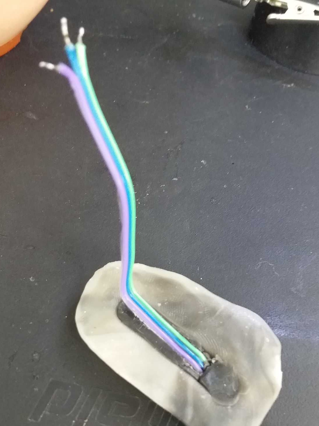
In my case, both the sensor and the electronics should not be placed on the wheel bracket, since the bracket (castor) itself rotates around its axis in a circular manner relative to the plane of the board.
Implementation. The transmission specification was chosen by BlueTooth because of the availability of this technology and its presence in the Samsung SM-V700 smartwatch at hand. BlueTooth module was selected HC-05, the controller Arduino Mini Pro, but subsequently replaced by the AtMega168A bare controller, a 500mAh Li-Pol battery was selected to meet the castor's dimensions and the estimated power consumption. As a rotation sensor, the Hall Sensor SS49E was chosen, in contrast to the prototype, as more operational stable. Accordingly, the sketch was slightly modernized. The passage of a magnet mounted in the wheel hub is analyzed by two points: the first actuation — the magnet enters the sensitivity zone - “platoon” and the second actuation — the magnet exits the sensor sensitivity zone - “descent”.The controller counts these events within a specified period of time - 1 second and sends the received number via the communication channel to the Android device, while simultaneously analyzing the incoming signals. The program for receiving, displaying, managing the module was created based on the prototype in the Android Studio environment. It provides for some improvements related to increasing noise immunity. Like the prototype, it calculates speed and distance. The useful function of turning on / off the "headlight" - an LED directed forward in motion - is also saved, as it seems.
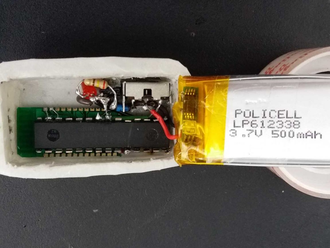
Visible top left: red charge reversal protection LED, charge-work switch, battery; below: the green BT module, the AtMega168A microcontroller with flush-cut terminals is glued on its back with the upper part of the case.
Assembled with the castor, the module looks like this:
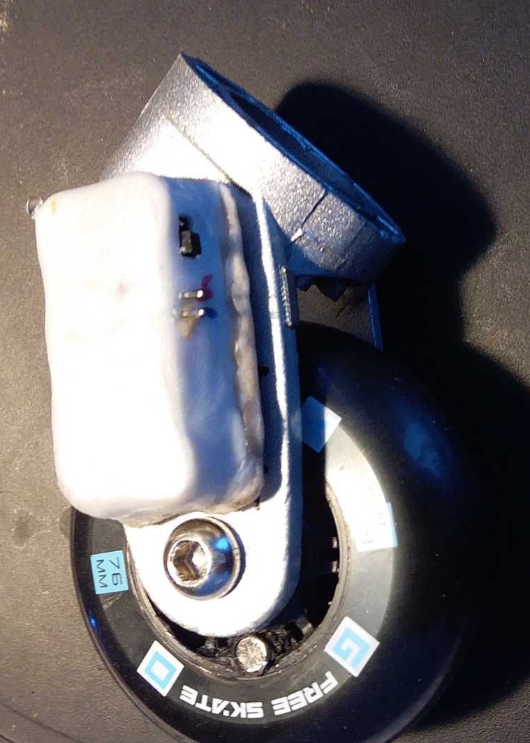
In the photo you can see the power switch, the contacts for connecting the charger, on the other side of the unit on the corner above - LED - "headlight".
The prototype program was supplemented with the ability to issue sound and vibration signals at various events (turning on / off the headlight, an alarm signal when exceeding the specified maximum speed limit).
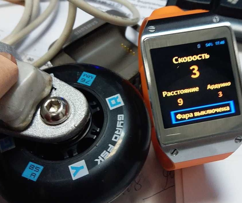
Testing on the table - in the photo below, not yet tested on the road, waiting for the summer :)
The Android Studio project has a large volume, I’ll post it somewhere with a link, if there is interest, I bring a sketch with comments.
In the presence of interest, I am ready to share ideas, experiences.