
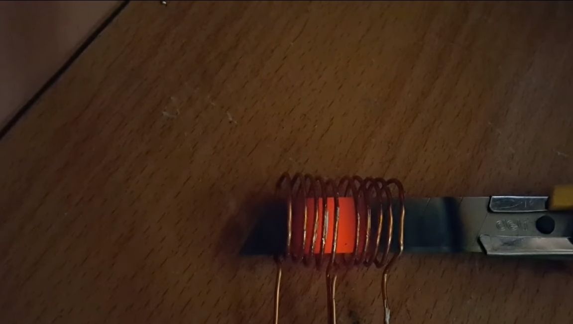
I bring to your attention a small one that works from a voltage of 12V DC. With this device, you can easily heat various metal objects. For example, you need to harden the tip of a screwdriver or other tool, this device will help you with this.
Induction heating fixtures good that there is no source of open flame, harmful gases and other things. This makes it possible to use a heater even in an apartment.
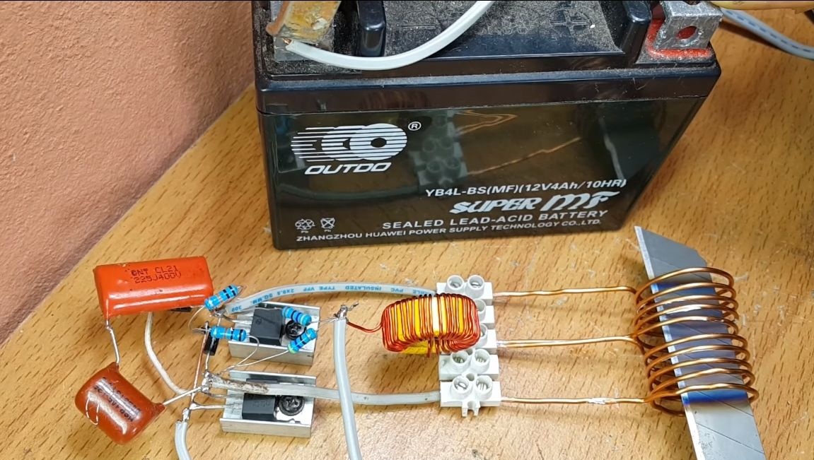
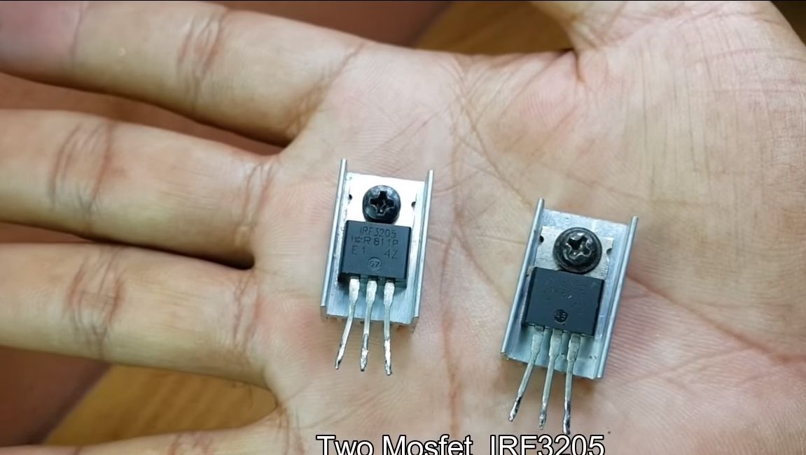
With the help of powerful induction heaters, you can not only warm, but even melt metals. But this homemade intended for educational purposes only, for beginners who want to try their hand at electronics. The heart of the machine is two IRF3205 mosfets; finding all the other parts is easy. So, let's start making homemade products.
Materials and tools for homemade, which the author used:
Materials:
- two ;
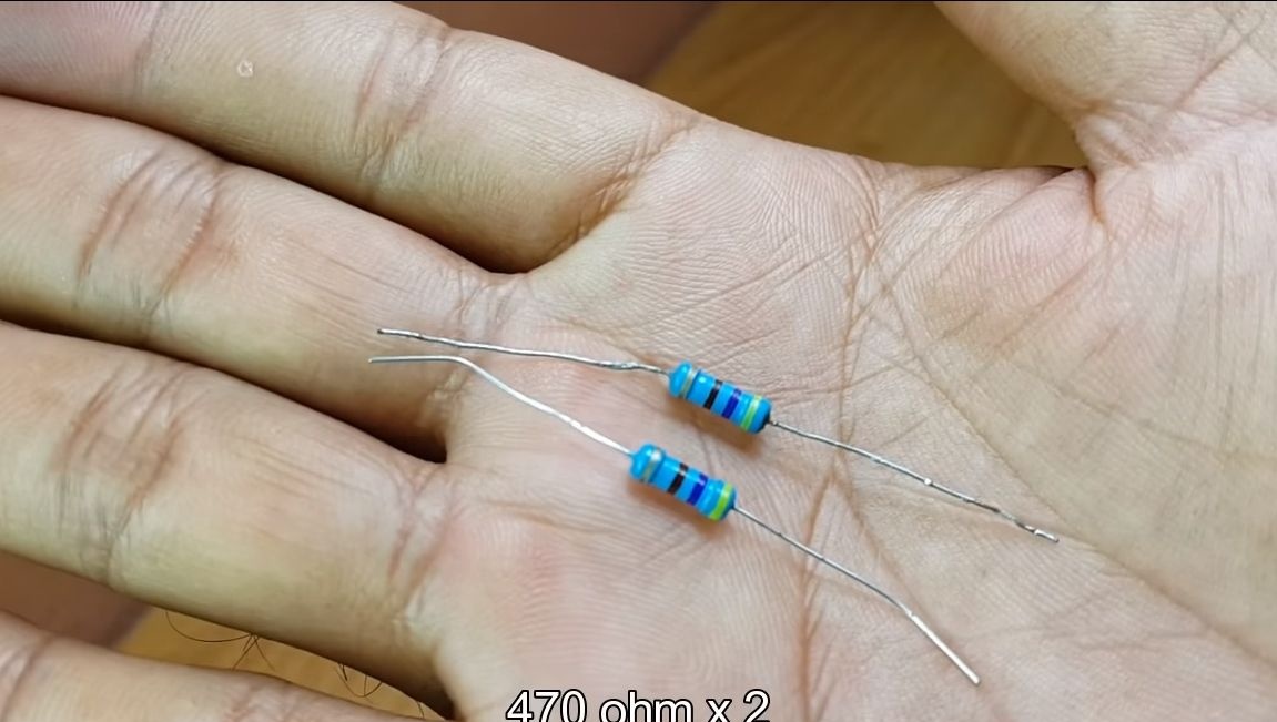
- two resistors 470 ohms;
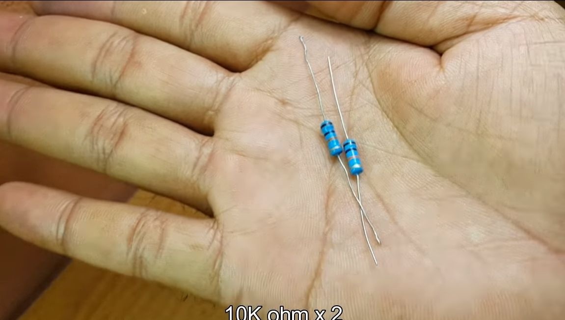
- two resistors 10 kOhm;
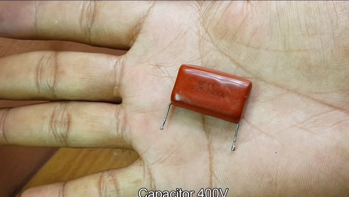
- capacitor 400V;
- two ;
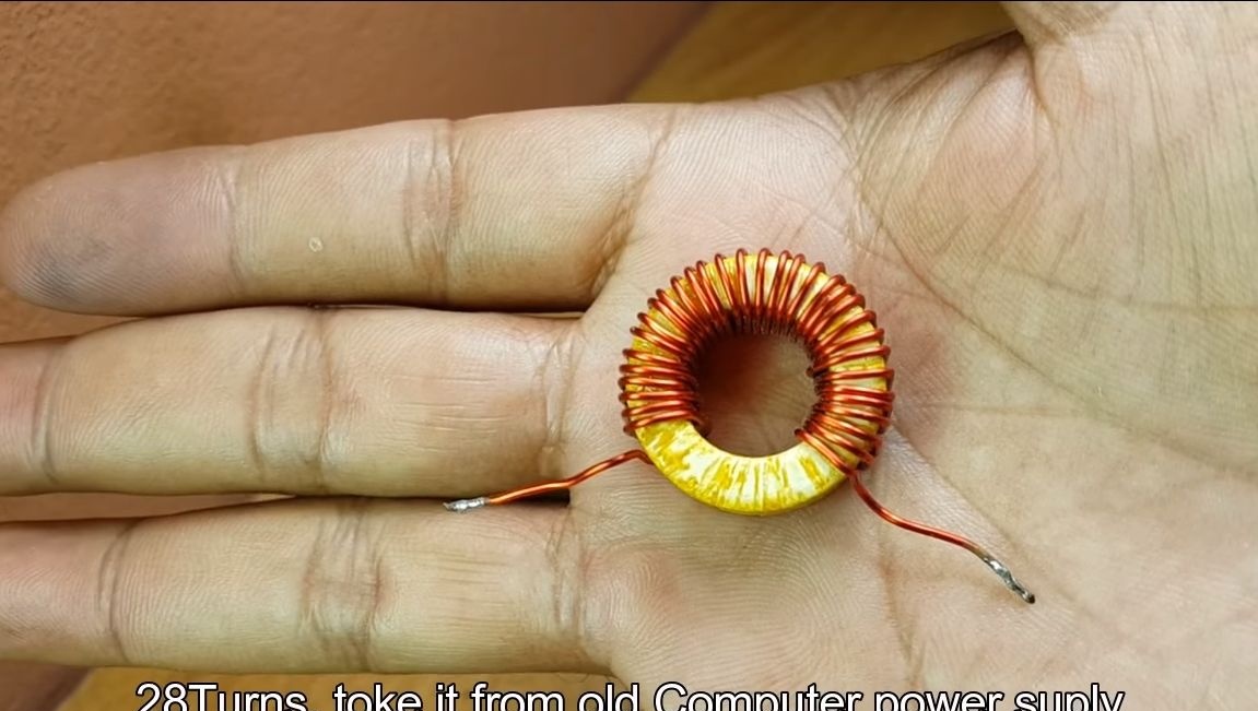
- throttle from an old computer power supply;
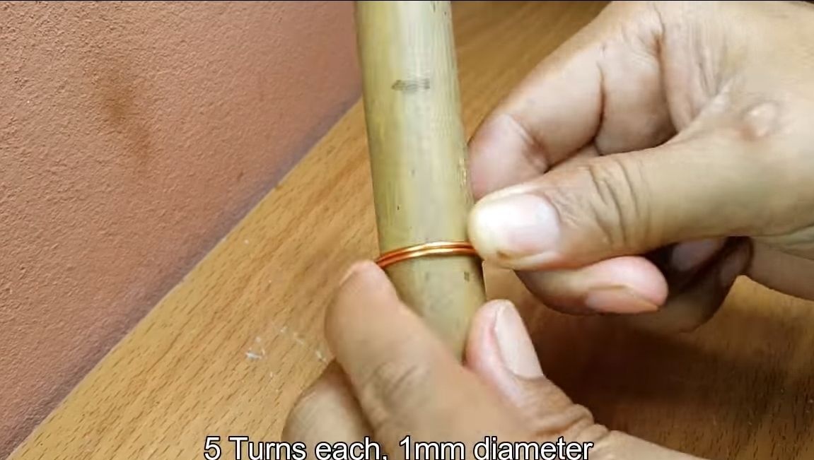
- copper wire 1 mm thick;
- 12V battery;
- screw clamps.
Instruments:
- soldering iron;
- nippers;
- multimeter;
- a piece of tube for winding the coil.
Heater manufacturing process:
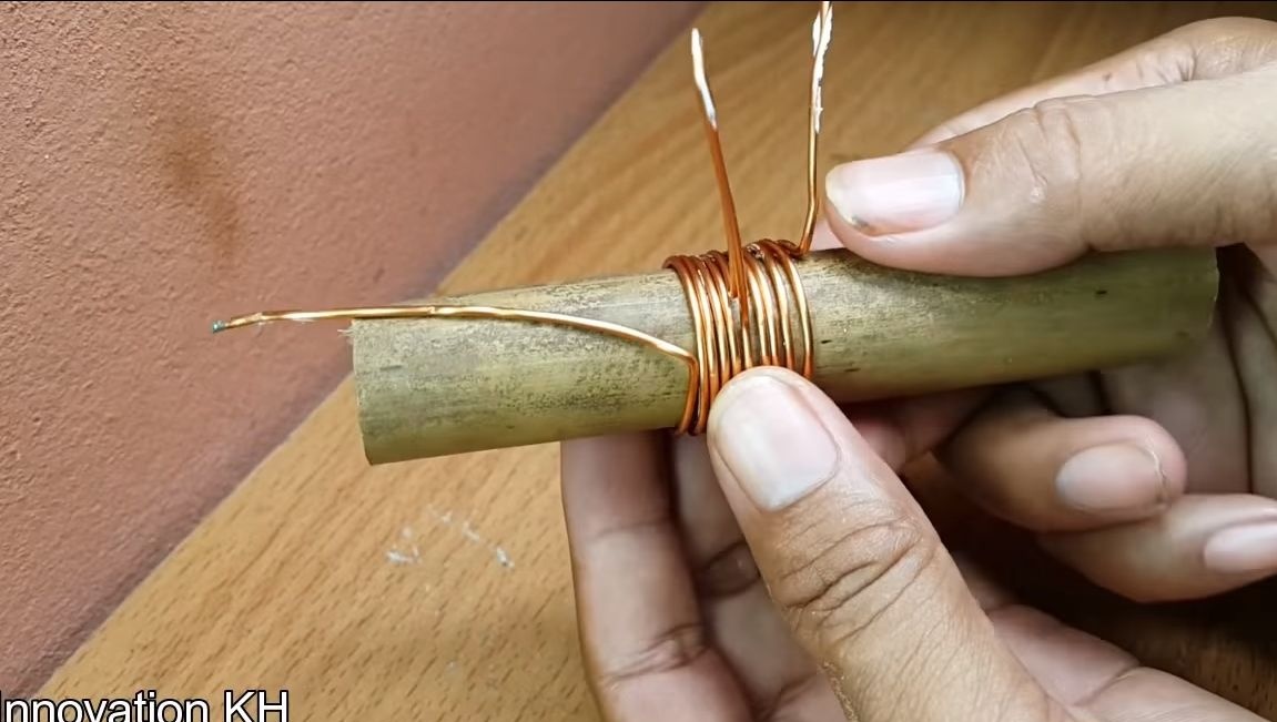
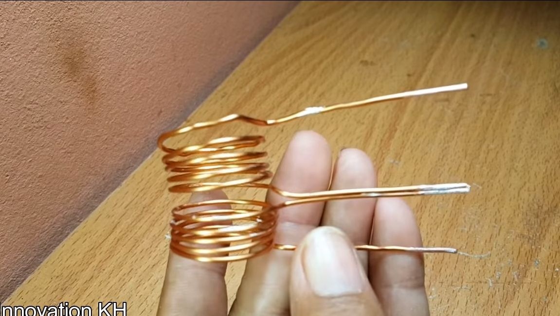
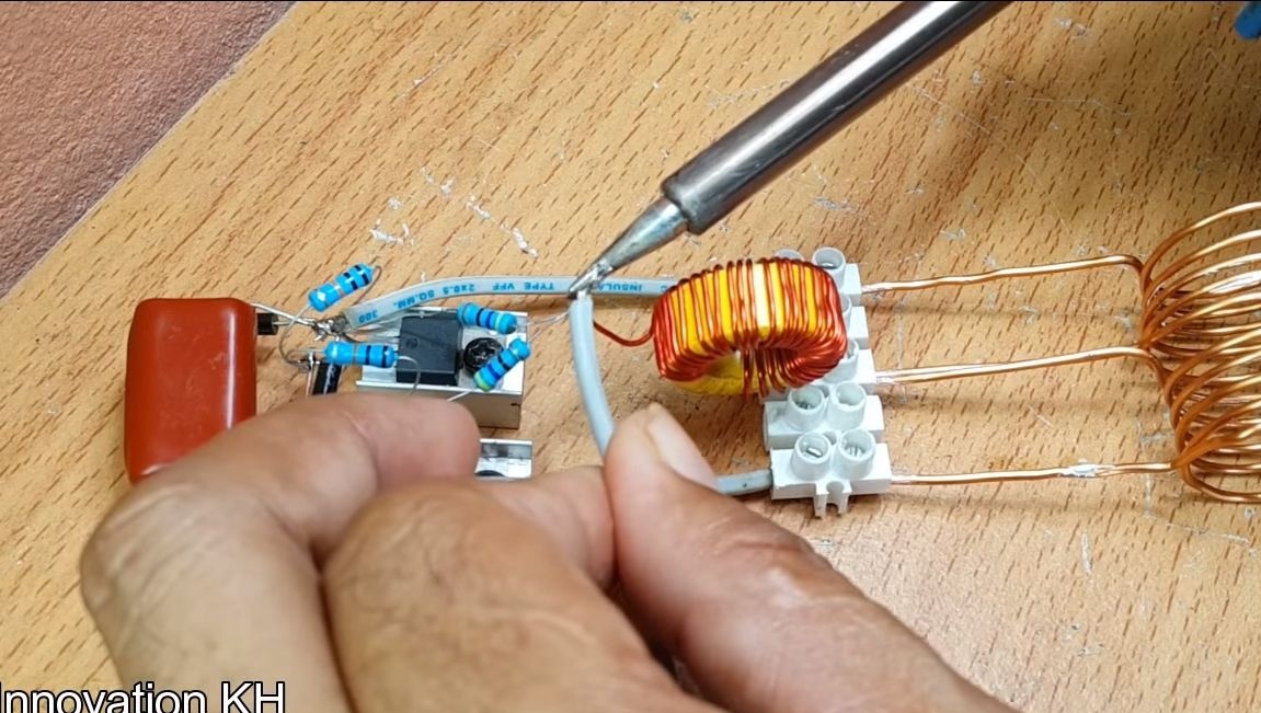
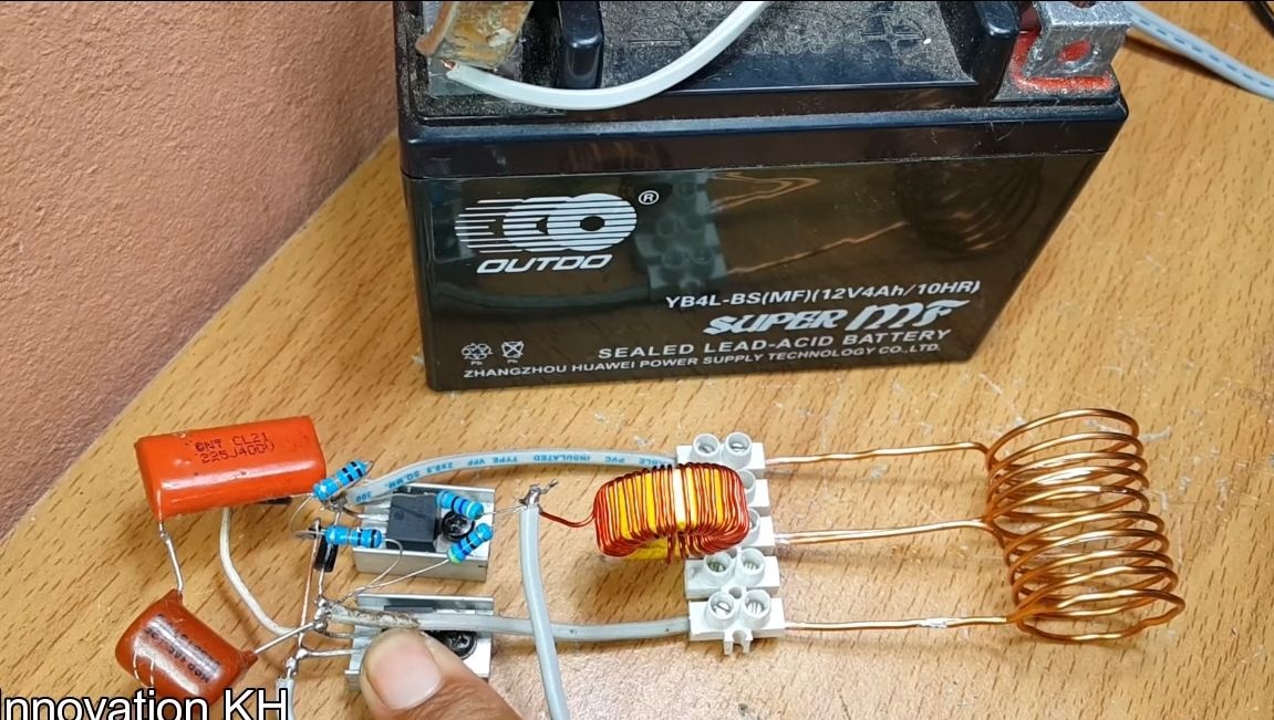
Step one. We make a coil
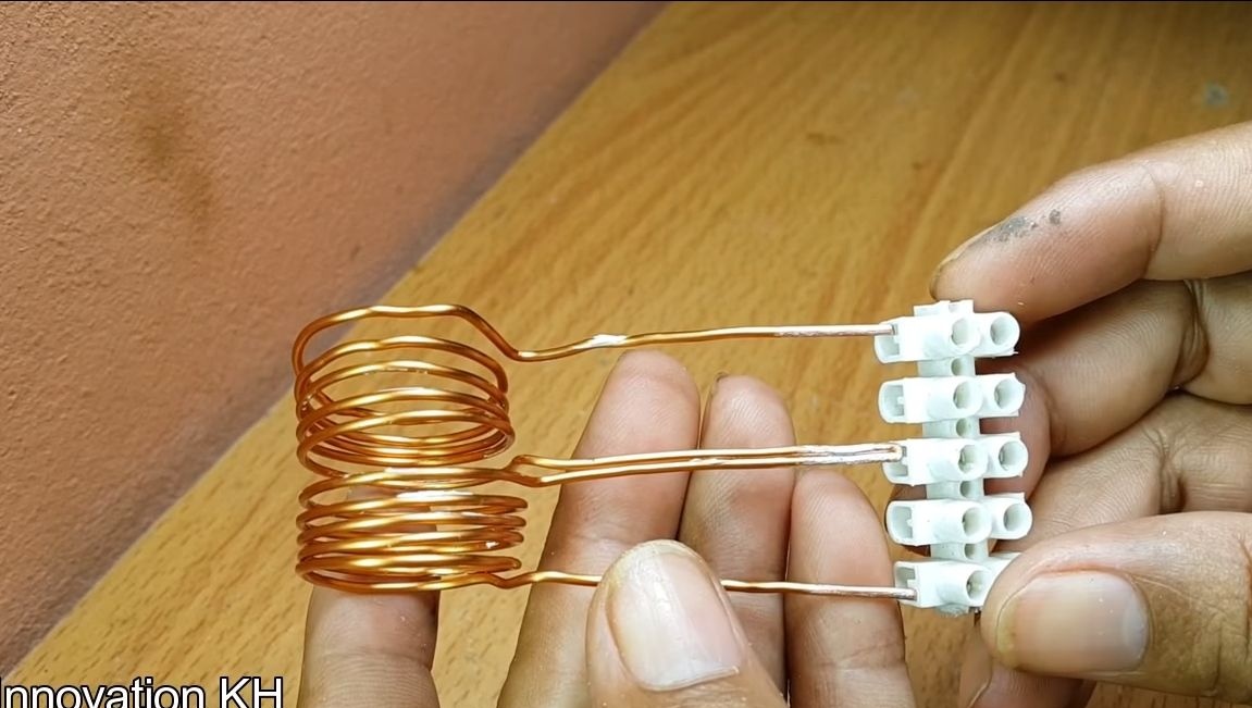
To make an induction coil, you will need a piece of tube or another similar item. We take a wire with a cross section of 1 mm and make 10 turns, after five turns make a tap. Now strip the ends of the wire and it is advisable to tin them so that there is good contact. Clamp the findings of the manufactured coil in the screw terminal block.
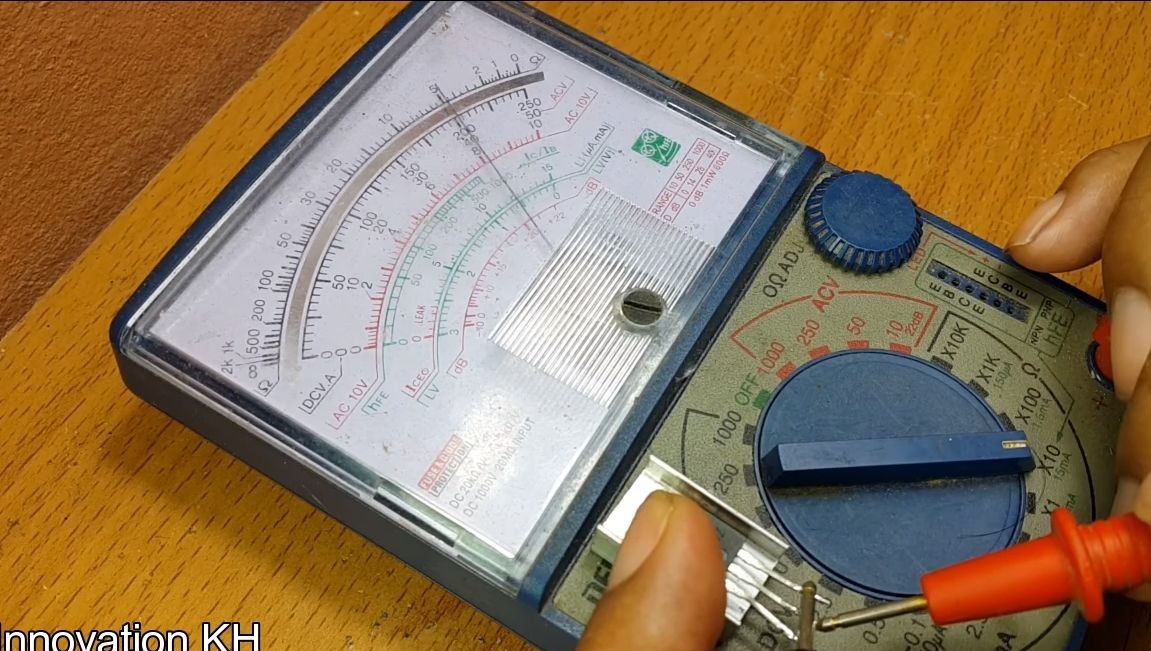
Step Two We deal with mosfet
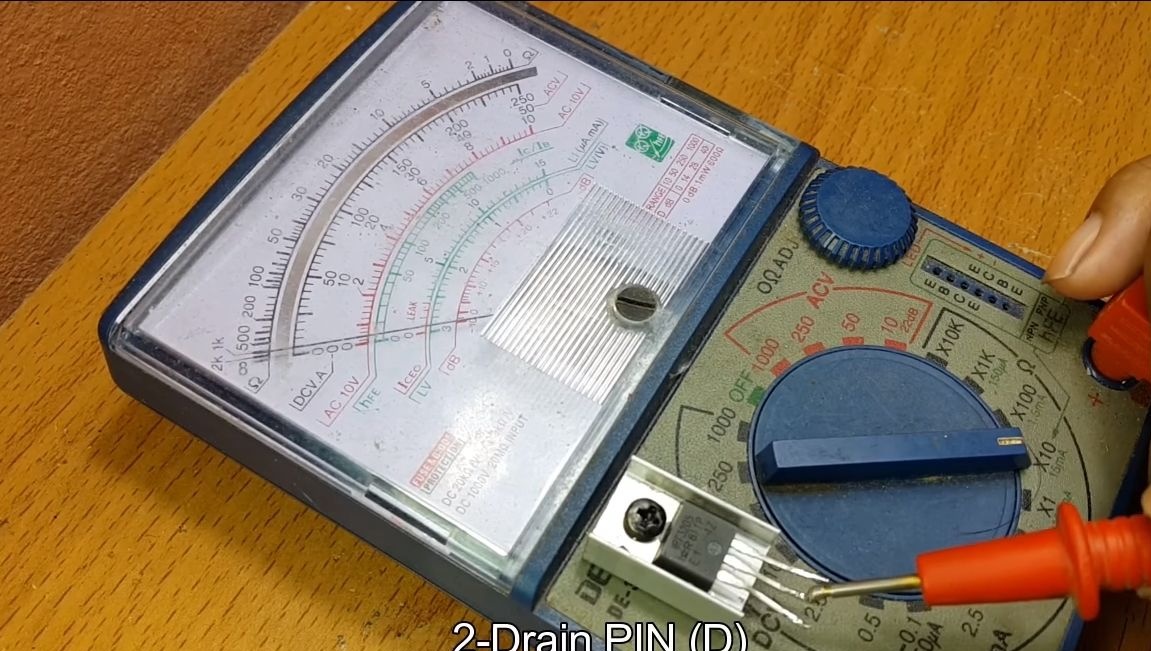
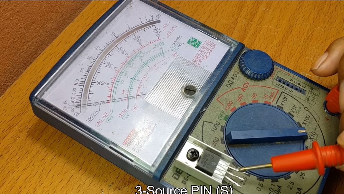
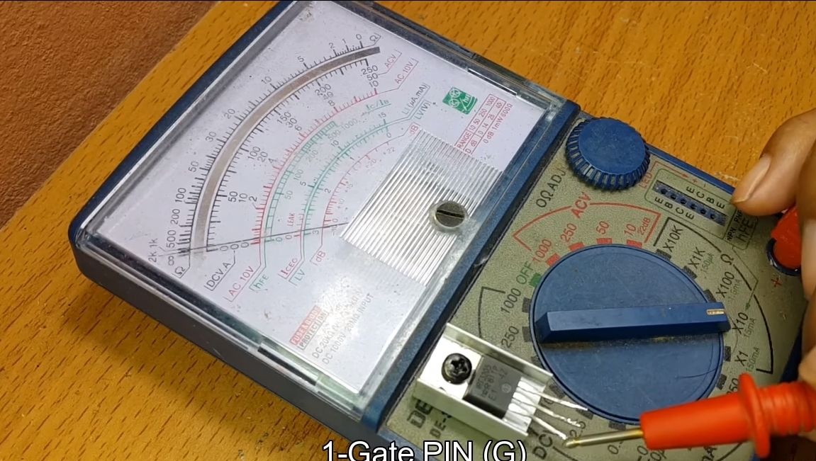
If you use a transistor of unknown labeling or do not know the connection diagram, you will need a multimeter to determine the necessary contacts. The drain at IRF3205 is the central contact. The left of it is the gate, and the right source.
Step Three Jumper
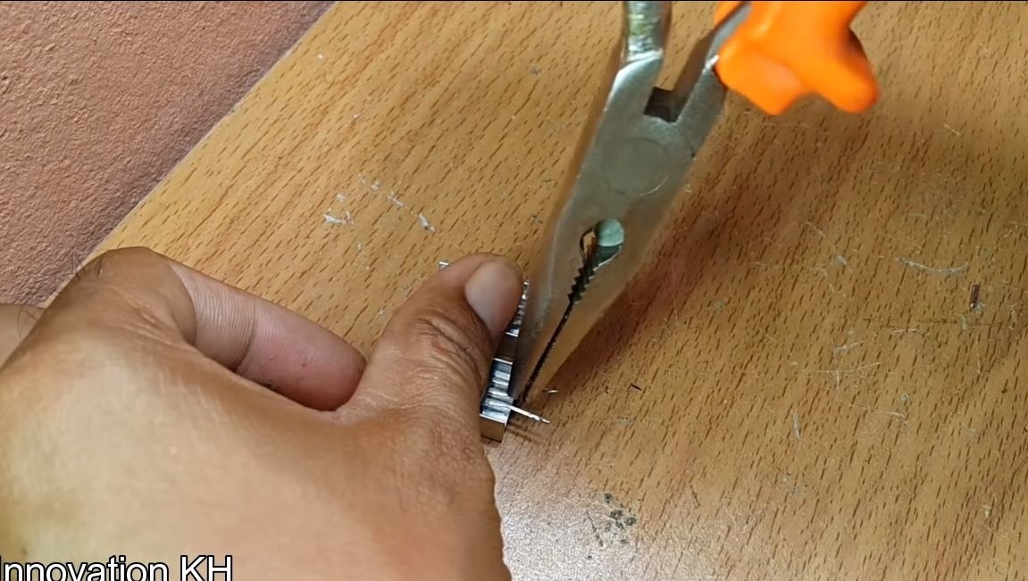
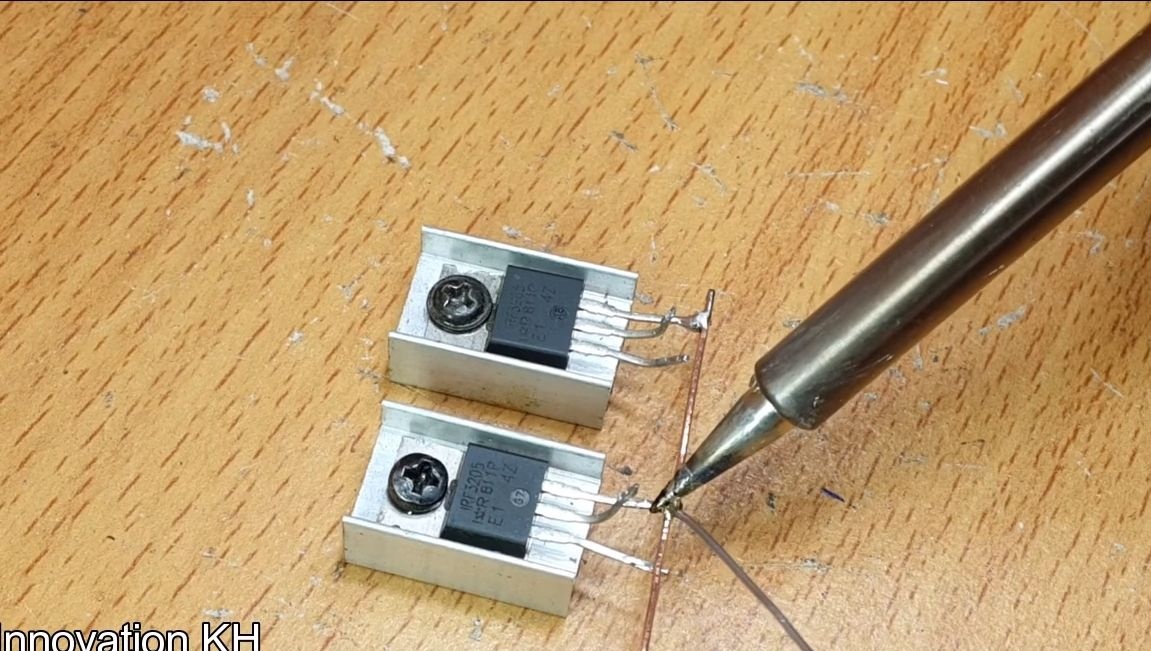
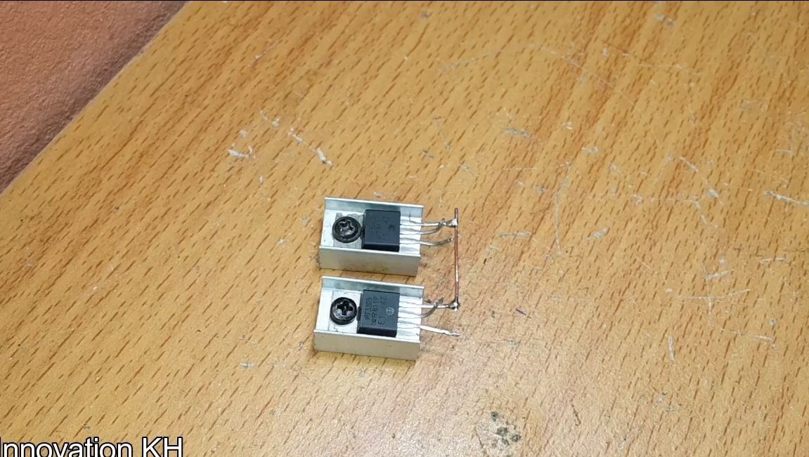
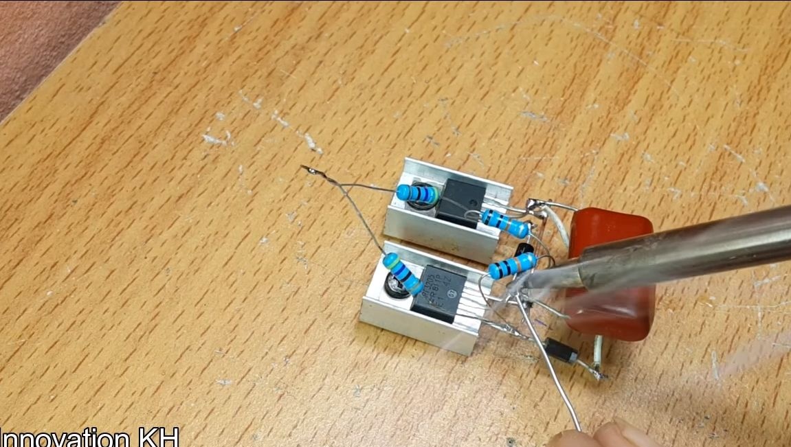
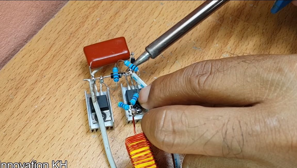
We begin to assemble the circuit. So that you do not get confused, everything is broken down in steps. First, you need to install transistors on a radiator, as they can get warm slightly. Next, take the pliers and bend the center legs up for easy connection.
We take a piece of copper wire and solder to the right legs on each transistor.
Step Four 470 ohm resistors
We take two 470 ohm resistors and connect the two ends, they need to be soldered well so that there is good contact.
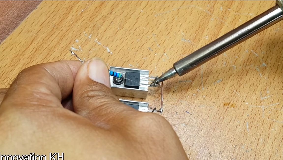
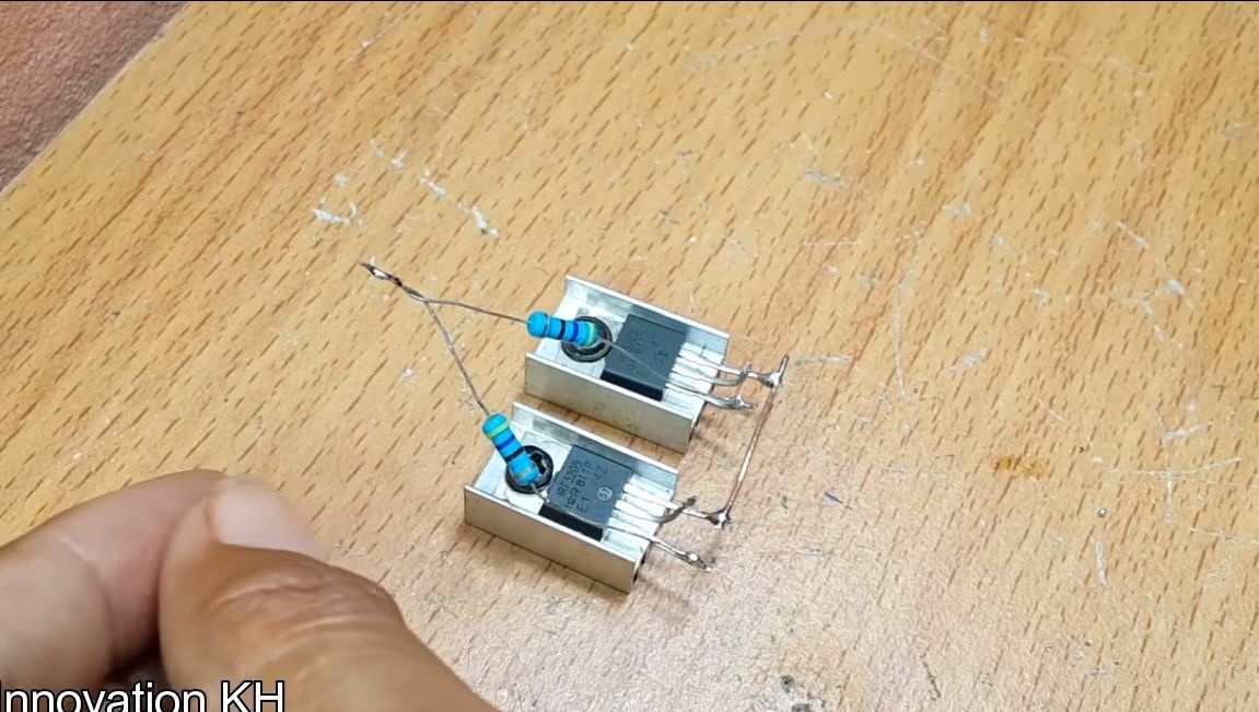
Further, the opposite ends are soldered to the leftmost legs of the transistors on both structures.
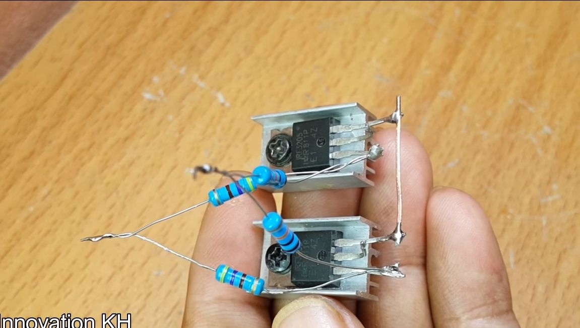
Step Five 10 kOhm resistors
Now set the resistors to 10 kΩ, they are installed in exactly the same order as the resistors and to 470 Ohms
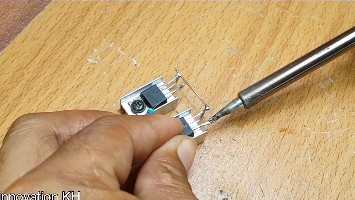
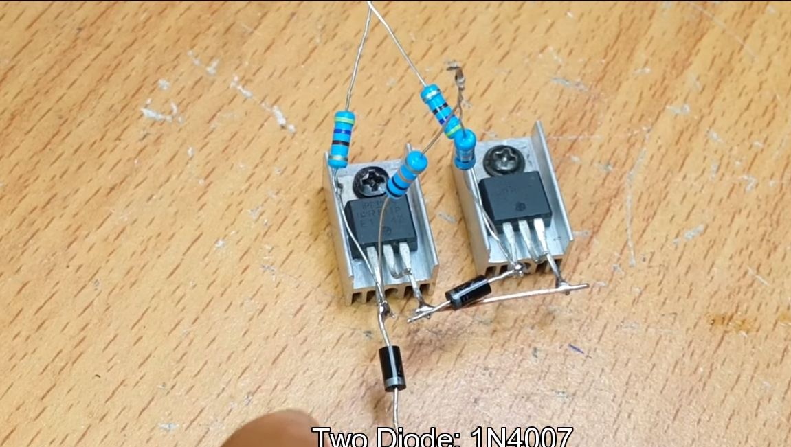
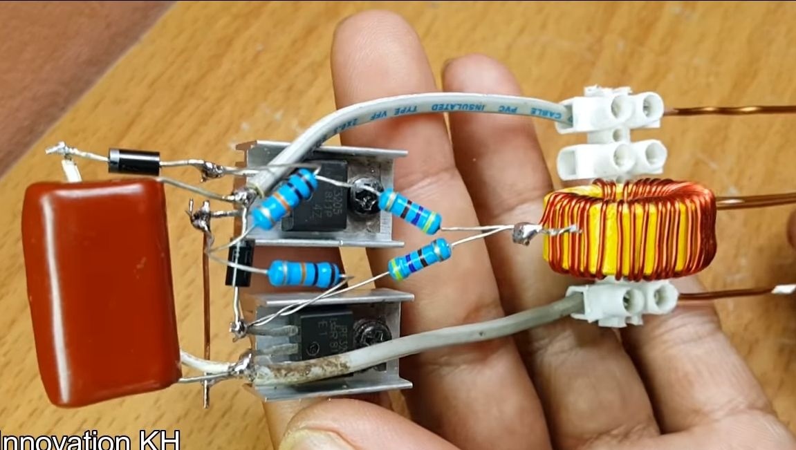
Step Six Install diodes
There are two diodes in the circuit, 1N4007 is suitable for these purposes. Diodes are soldered to the two extreme left legs. Solder need "positive" contacts of the diodes.
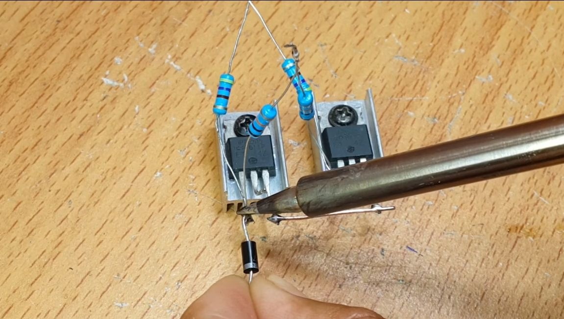
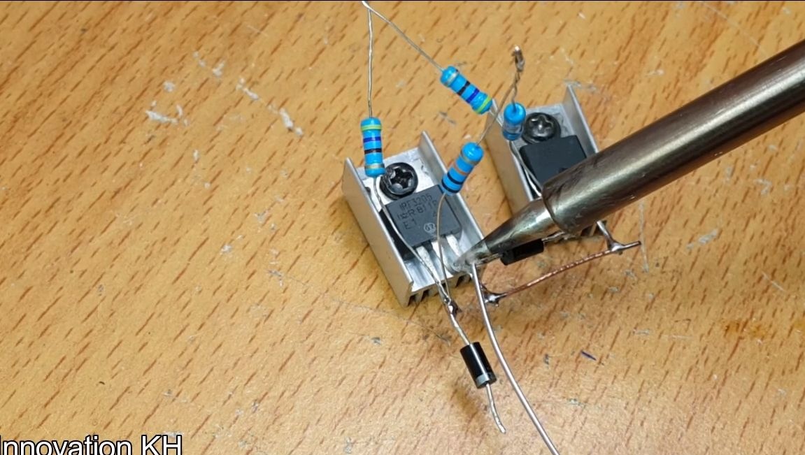
Next, solder the wire to the diode on the left, its other end is soldered to the middle pin on the transistor located on the right.
As for the right diode, its other contact must be soldered to the central leg of the left transistor.
Seventh step. The remaining ends of the resistors 10 kOhm
The opposite ends of the 10 kΩ resistors must be soldered to the jumper installed in the first step, that is, to the rightmost contact of the transistor located on the left.
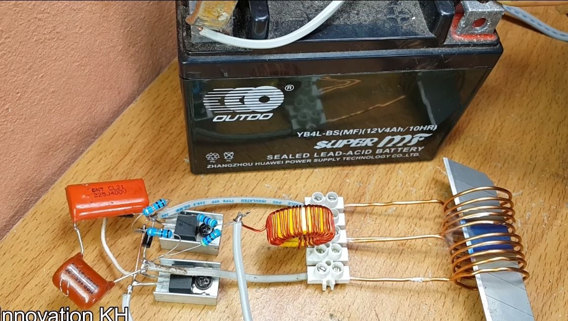
Step Eight. Install the inductor and capacitor
You can easily find such an inductor in an old power supply unit from a computer. We connect one contact to the central contact on the inductor. Another pin connects to the remaining ends of the 470 ohm resistors.
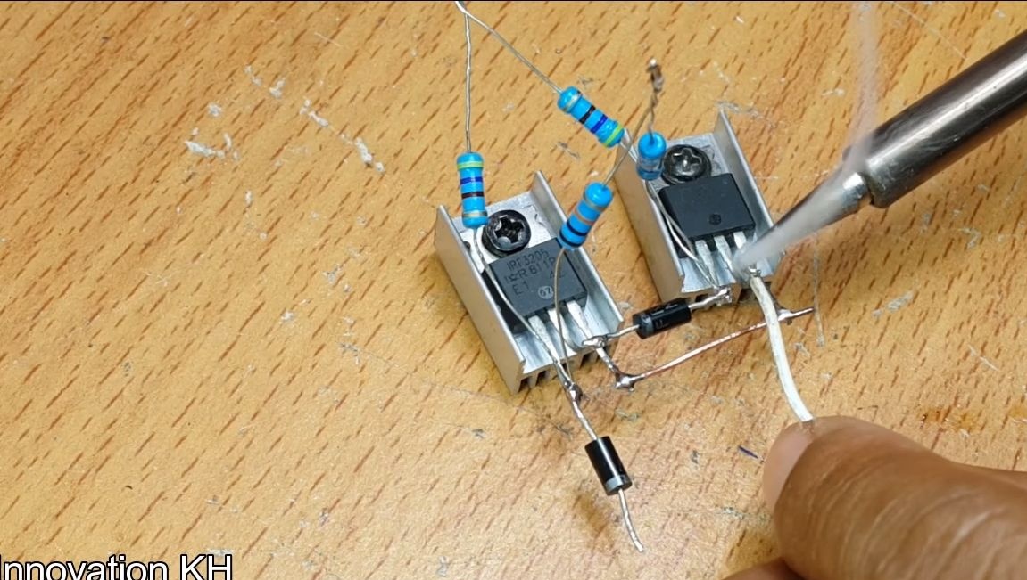
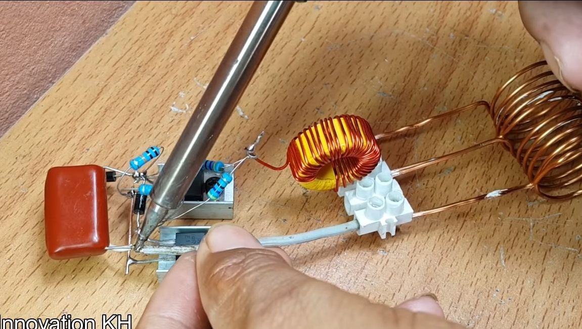
A 400V capacitor must be soldered to the central legs of the transistors.
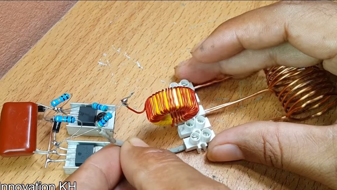
The coil will still have two more free conclusions. We take pieces of wires and solder them to the central legs of the transistors. Well, we connect the other ends of the wire through a screw clamp to an inductive coil.
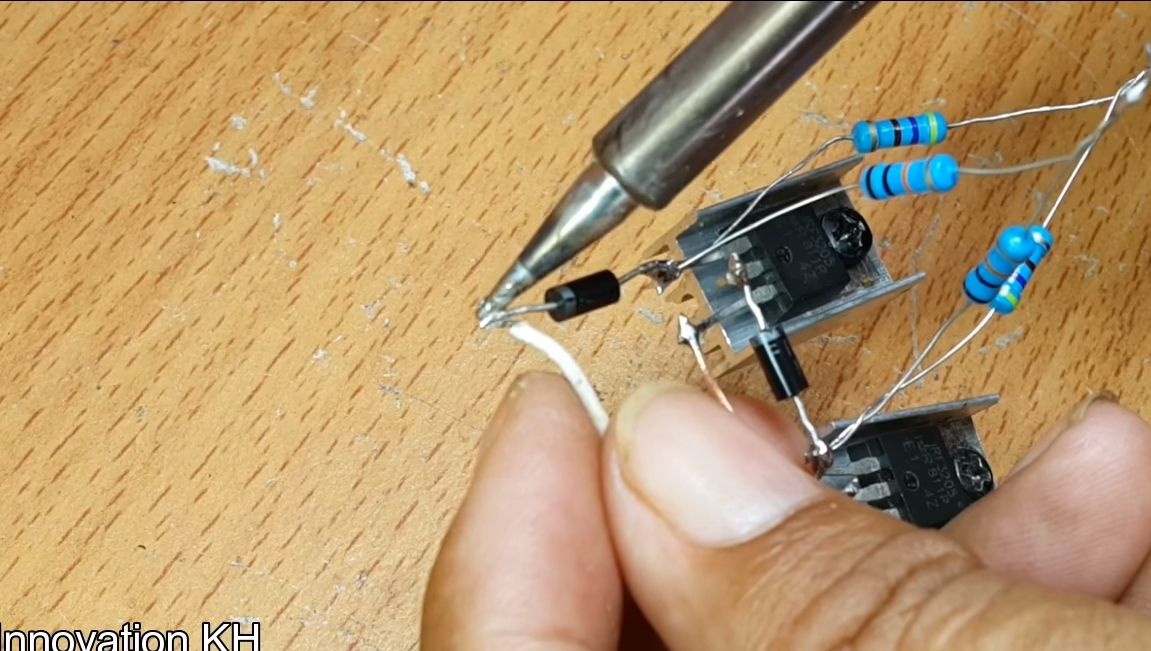
All that remains for you is to connect the power wires. We solder one to the inductor, and the other to the leftmost leg of the transistor, if you look at the transistors backwards.
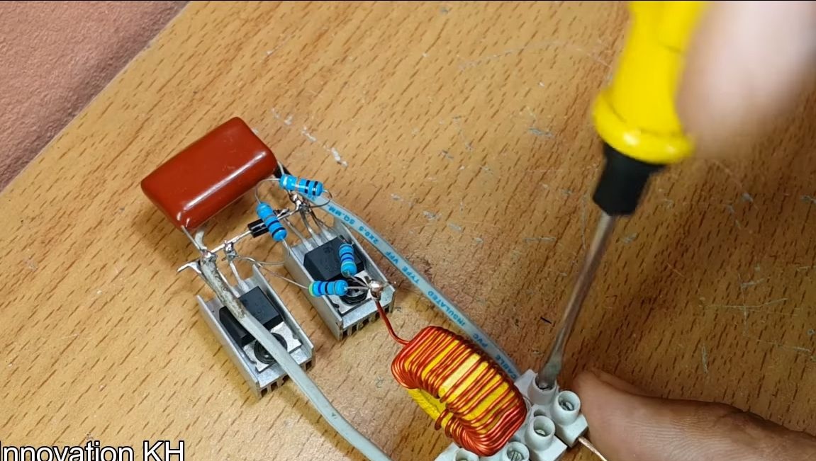
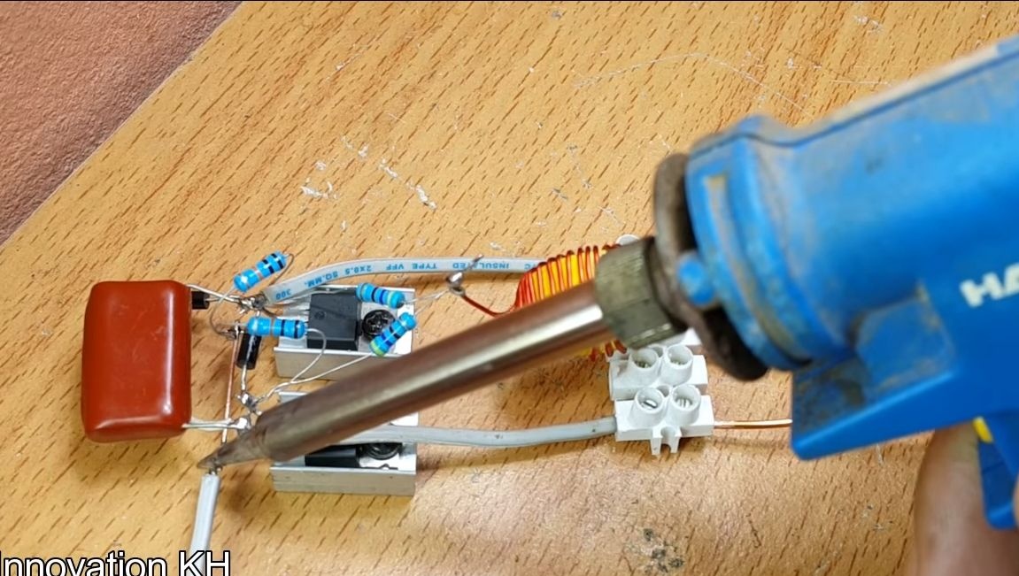
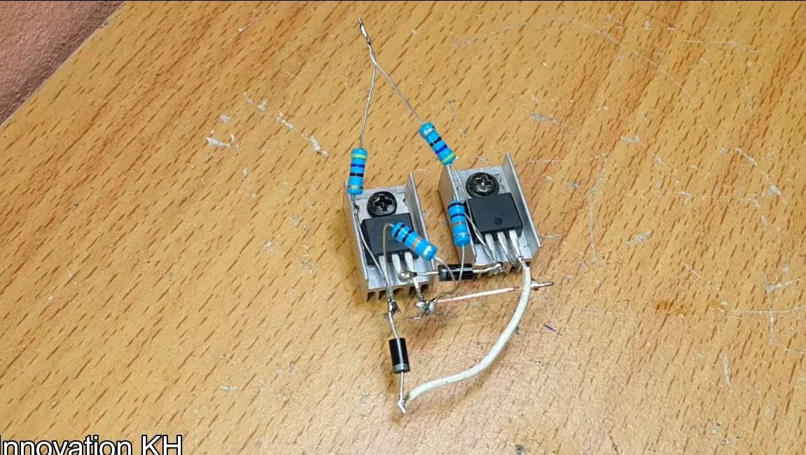
Step Nine. We are experiencing!
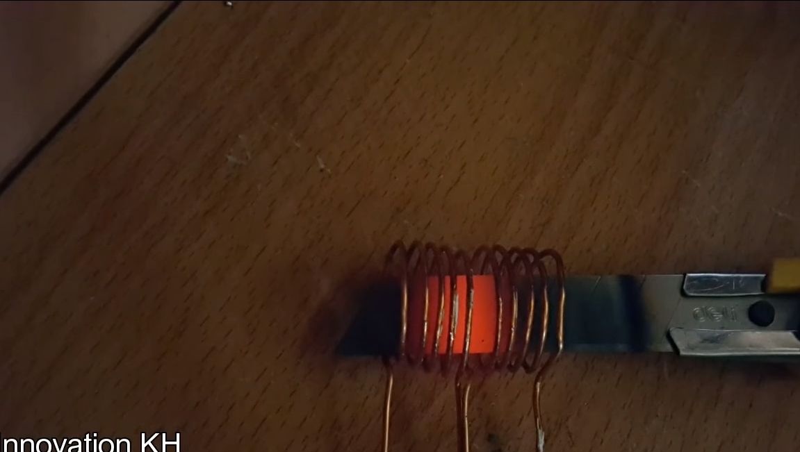
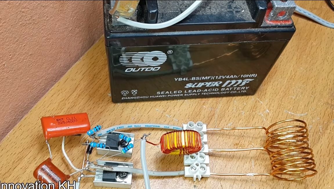
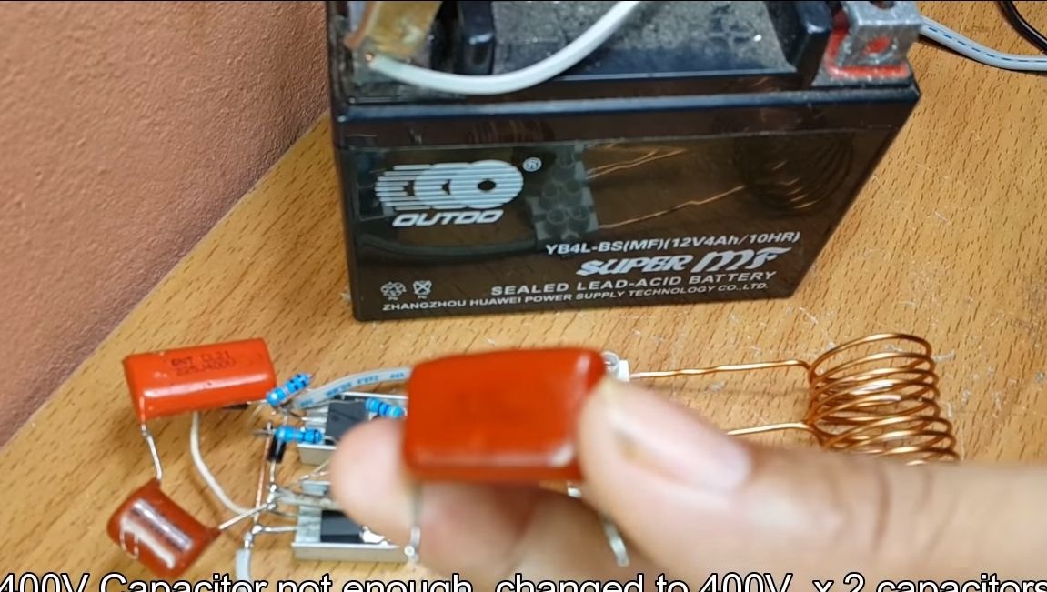
The homemade product is ready, it remains only to apply food and see what happens. The author demonstrates the operation of the device by heating a blade from a clerical knife. First turn on the device for a short time and make sure that transistors and other elements do not heat up. The author also recommends that instead of one capacitor, use two connected in series.
That's all, the homemade product is ready. Hope the material was helpful. Good luck and take care!