
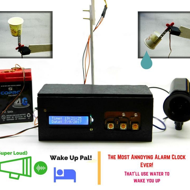
The author devoted this project to those people who are difficult to climb (and to himself, including). To a greater extent this applies to the student community, to which the Master also belongs. The features of this alarm clock are the following performance characteristics (performance characteristics):
- A powerful call is used bicycle electrical signal.
-If within 30 seconds you did not turn off the signal, then a glass of water is poured onto you.
- You can turn off the signal only 5 times by pressing the button corresponding to a randomly lit LED.
Tools and materials:
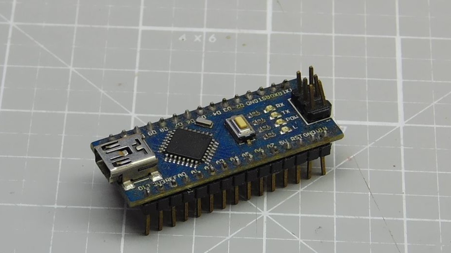
-Arduino Nano;
-Servomotor;
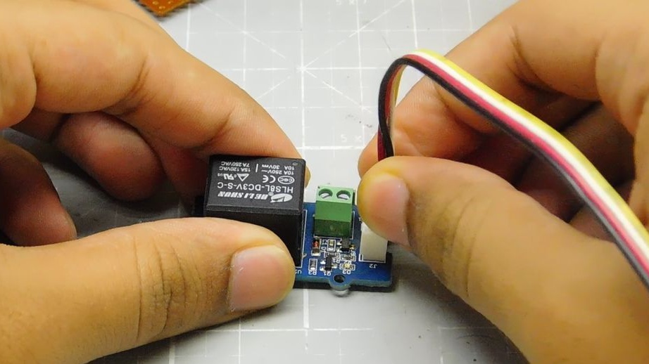
-Relay module for Arduino;
-Potentiometer;
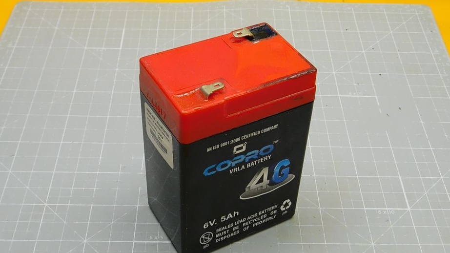
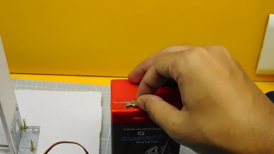
-6v 5Ah lead acid battery;
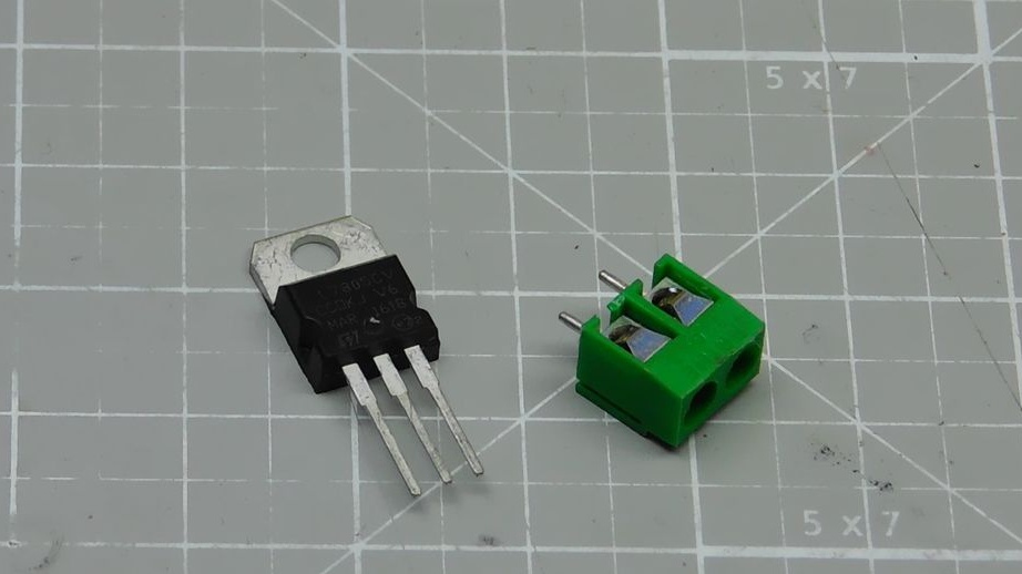
- Voltage Regulator L7805;
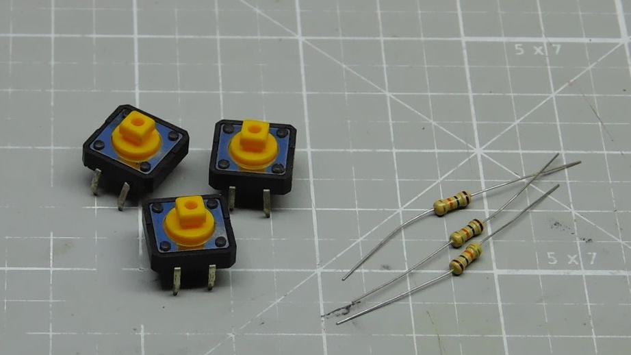
-Buttons - 3 pcs.;
- Resistors 3 kOhm - 3 pcs;
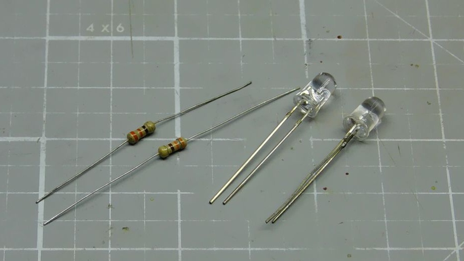
-LED red;
-LED green;
- Resistor 330 Ohm - 2 pcs.;
-Terminal block;
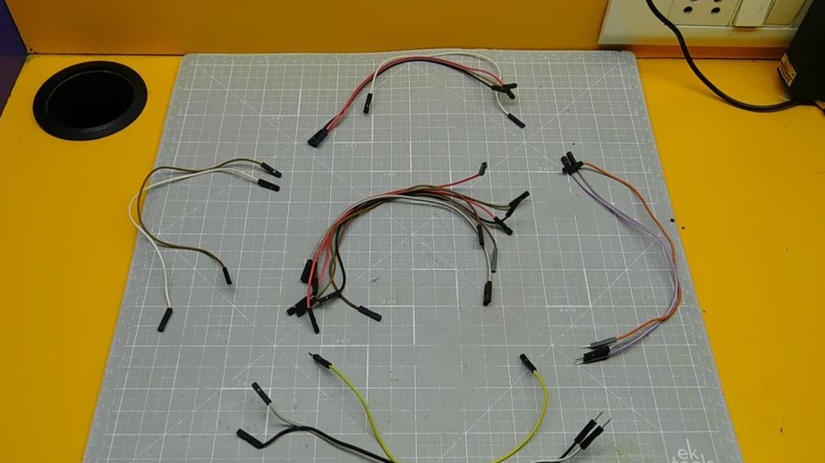
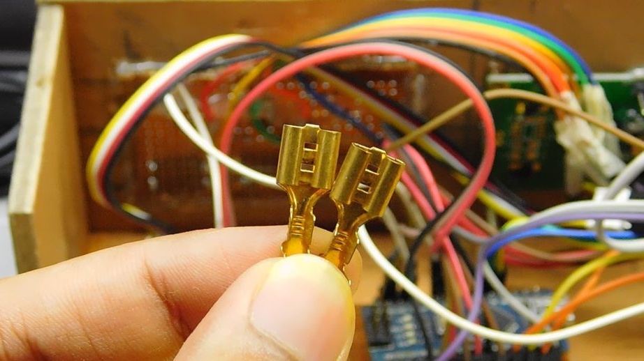
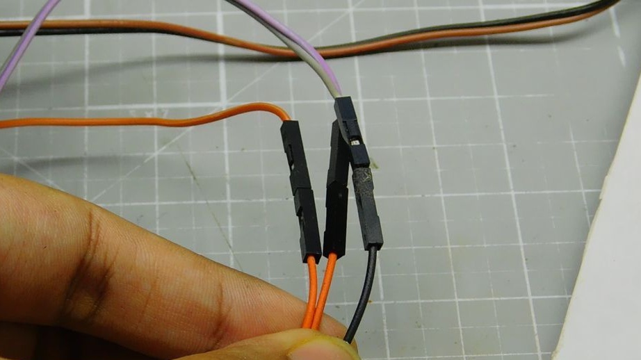
-Pin connectors;
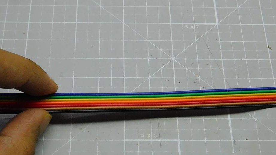
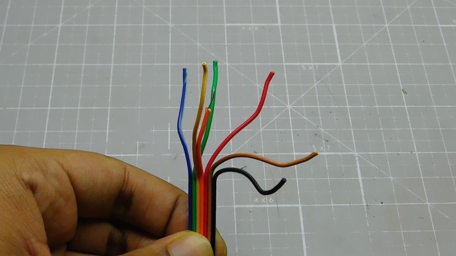
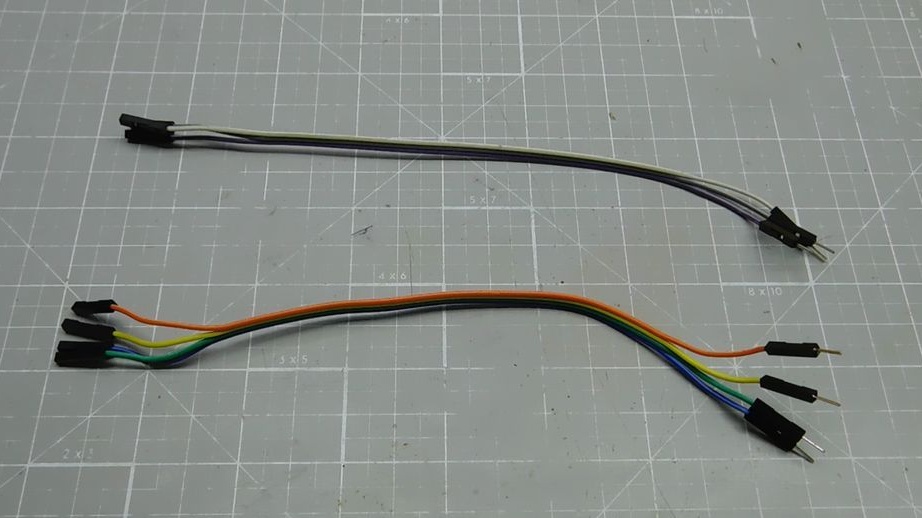
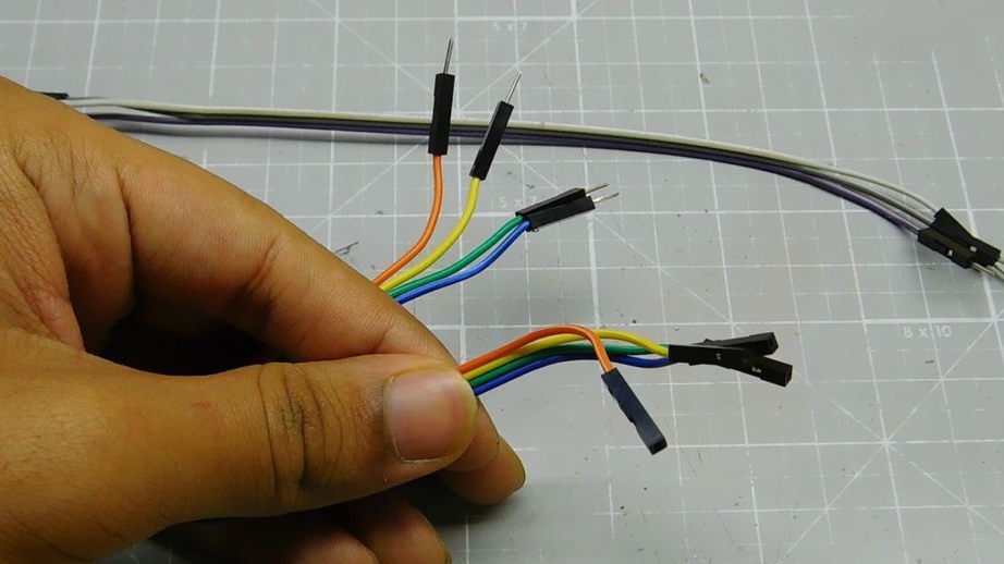
-Jumper wires;
-Circuit board;
-Plywood;
- Spray can with paint;
-Disposable cup;
-Soldering iron;
-Solder;
-Glue gun;
-Engraver;
-Pliers;
-Nippers;
-Hacksaw;
-Screwdriver;
-Glue;
-Rule;
-Pencil;
-Insulating tape;
-Sandpaper;
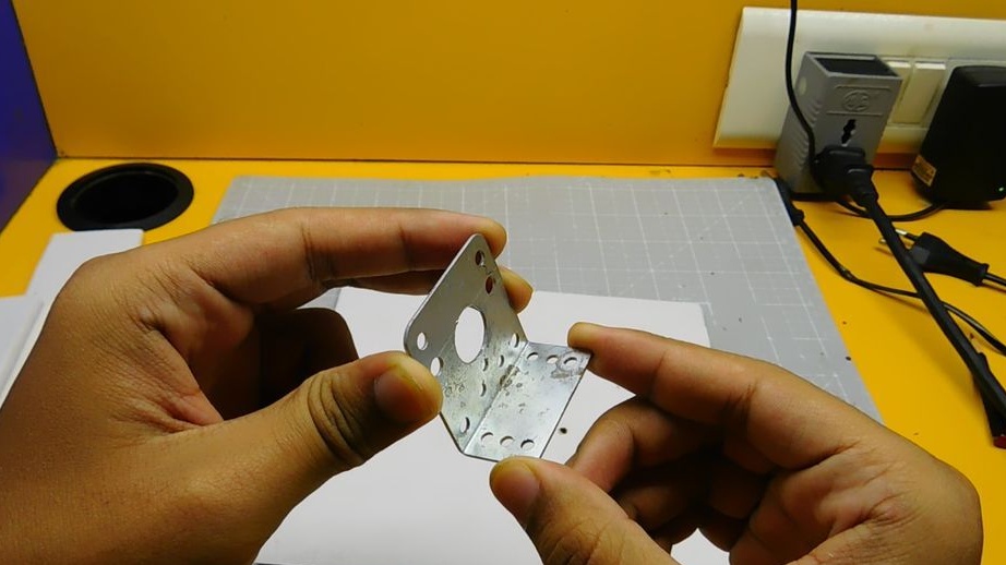
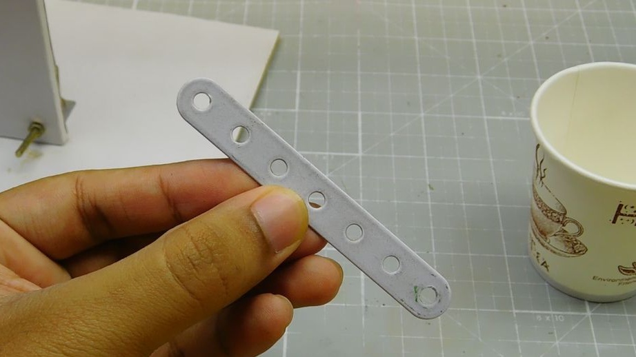
-Bracket;
-Fasteners;
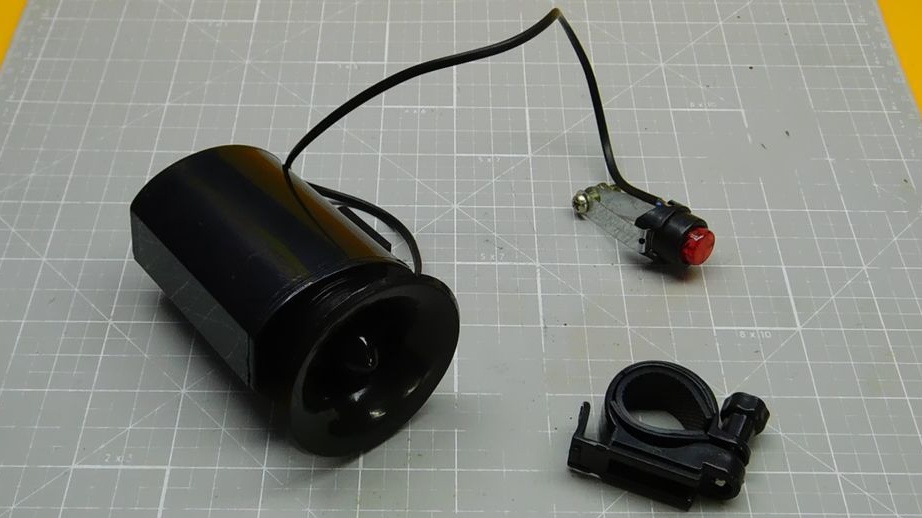
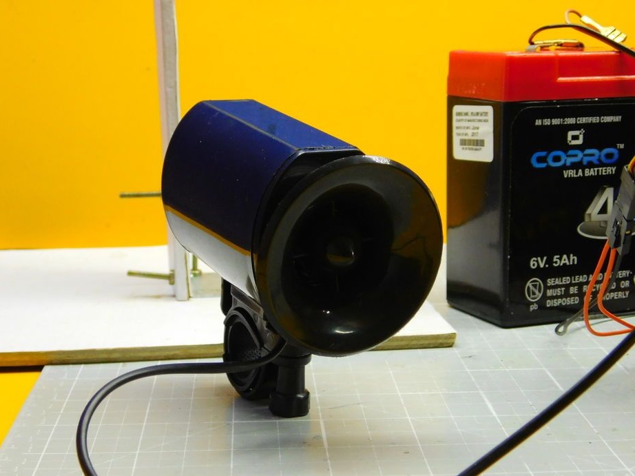
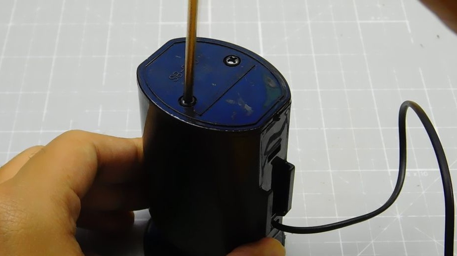
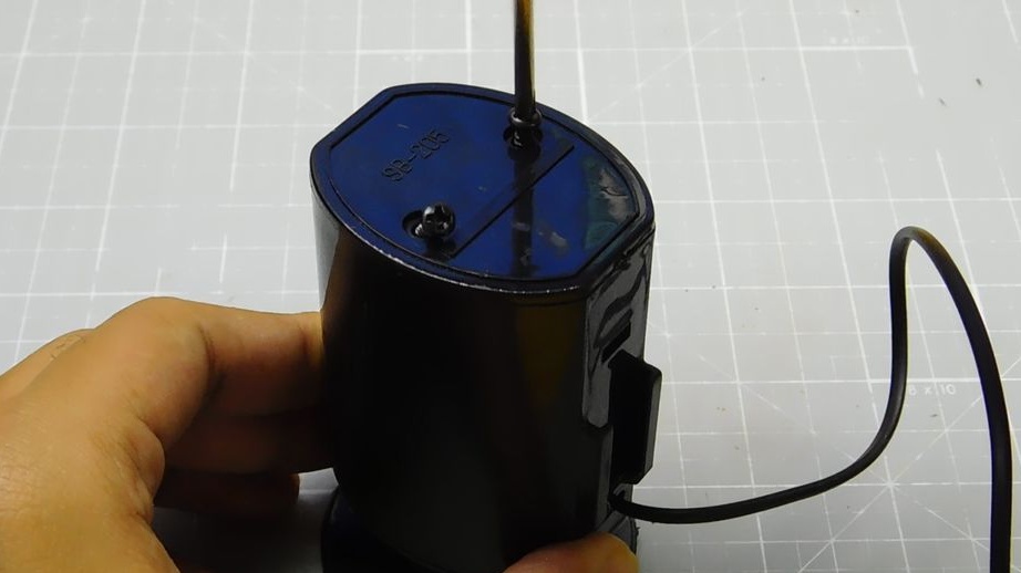
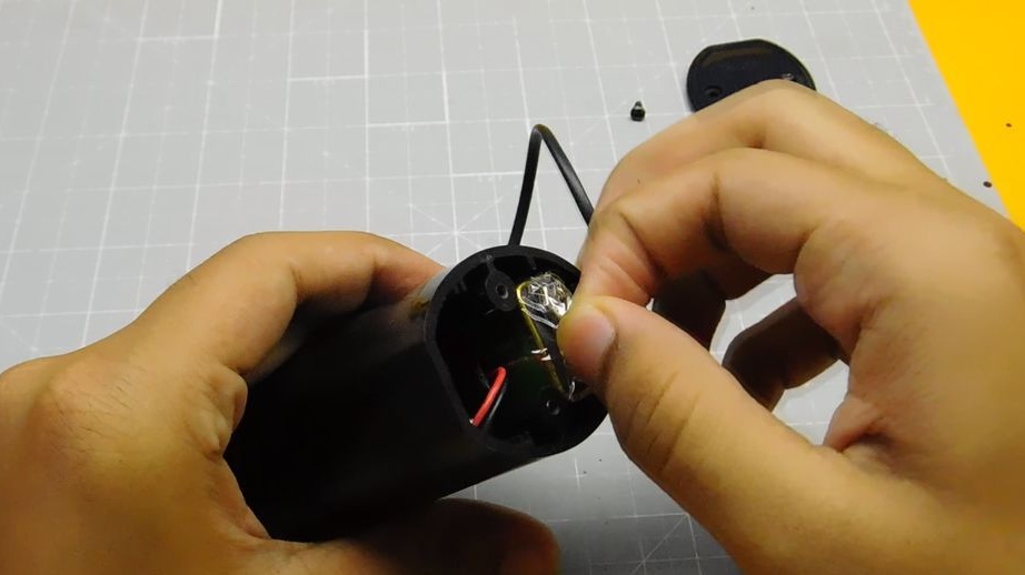
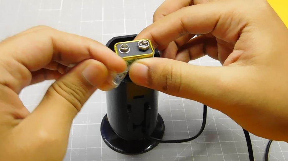
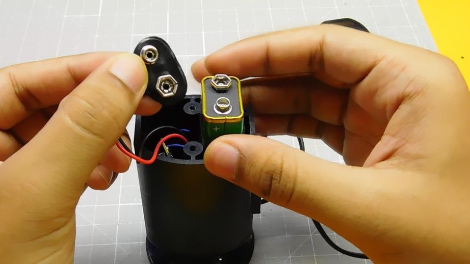
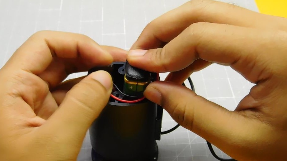
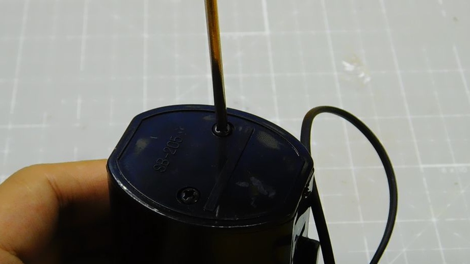
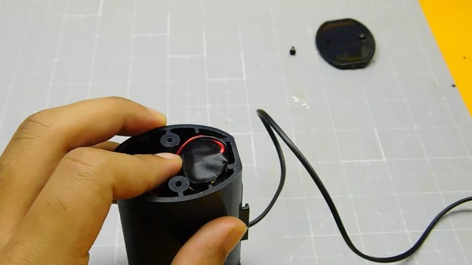
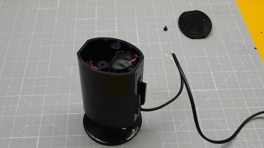
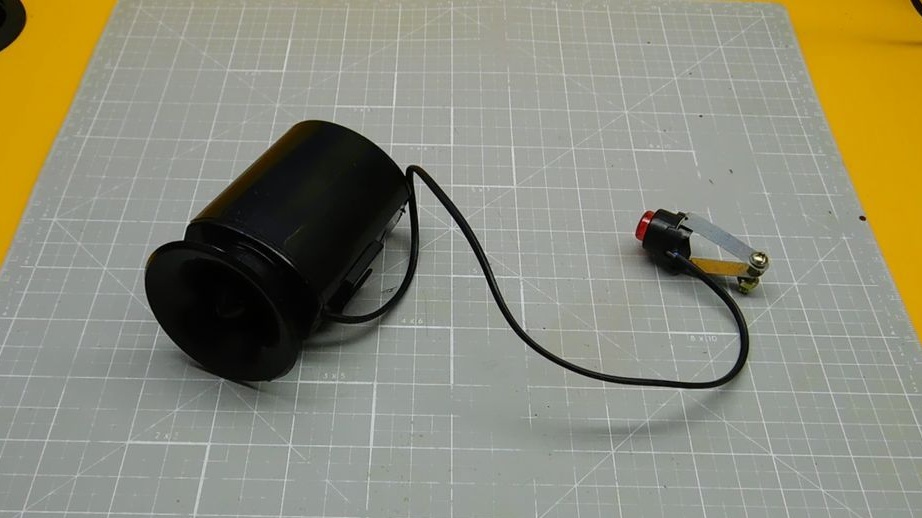
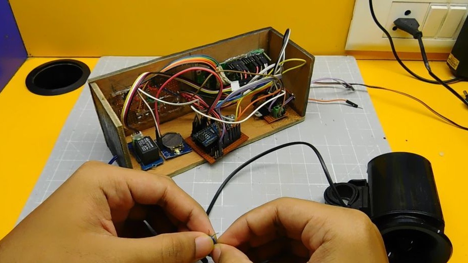
Step One: Bicycle Horn
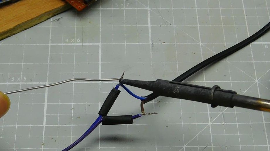
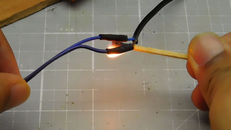
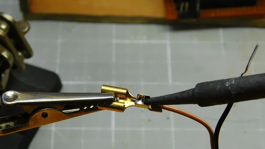
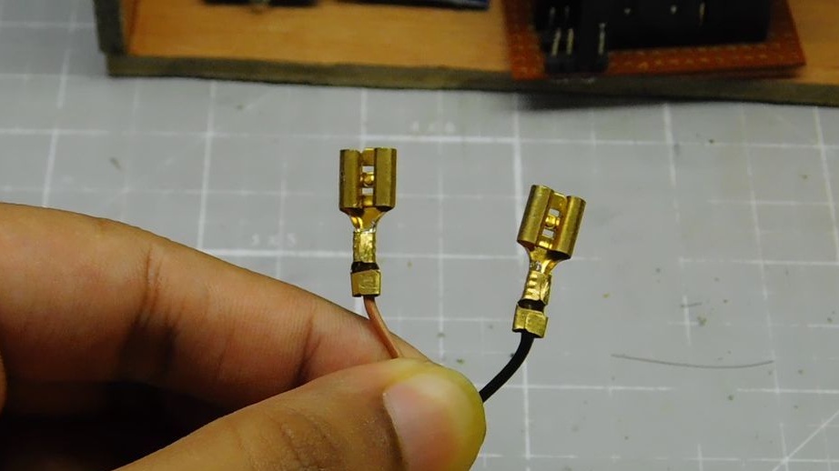
The bicycle horn has a built-in 9V battery, such as a Krone. To connect it, you must open the cover and connect the connectors to the battery terminals. The button included in the kit is not needed, so the wizard cuts it off.
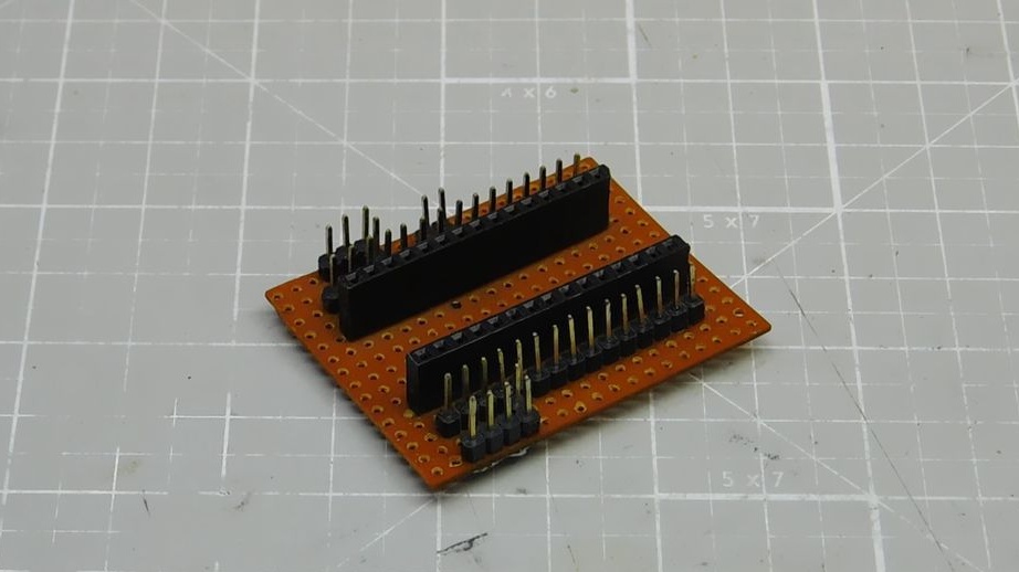
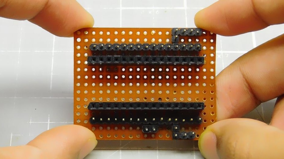
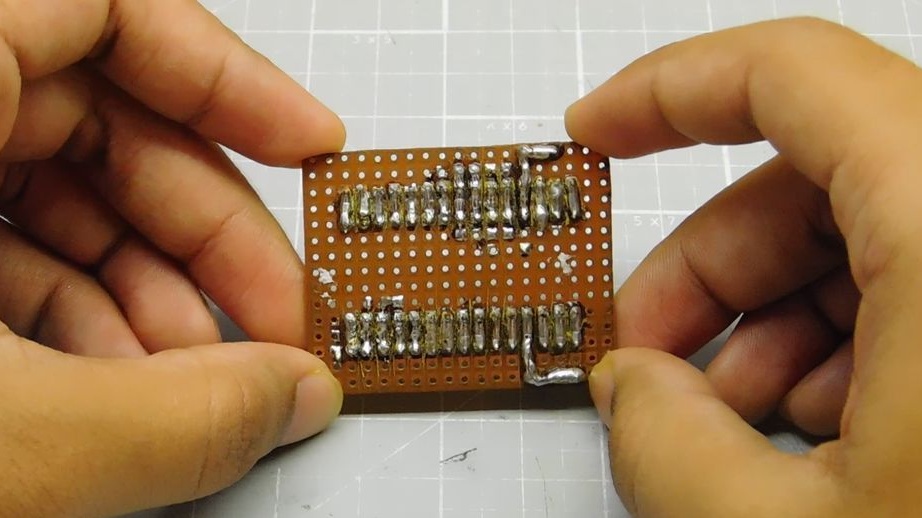
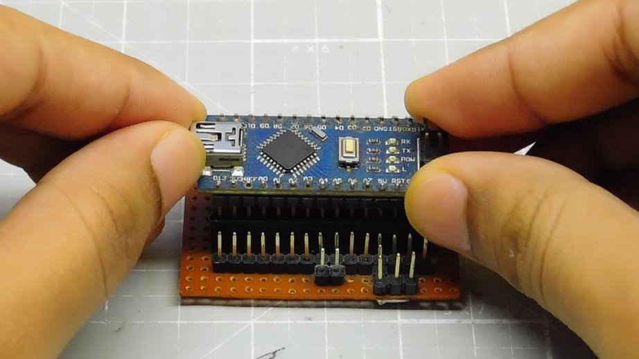
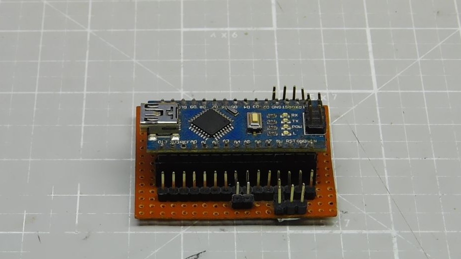
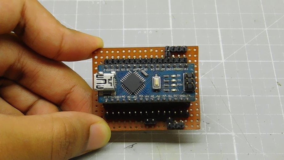
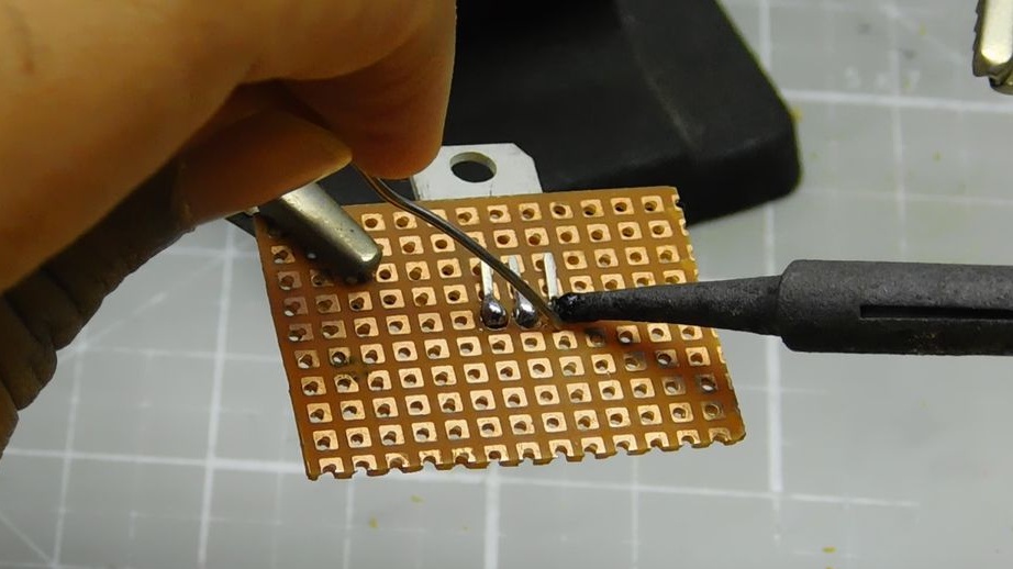
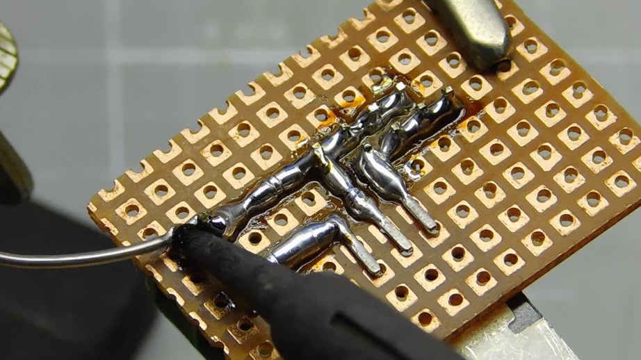
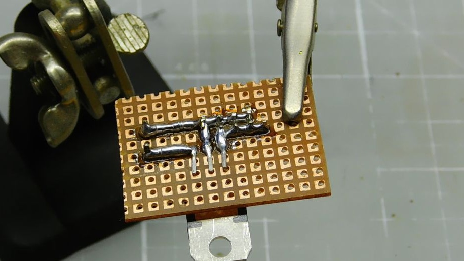
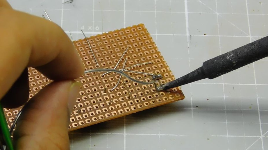
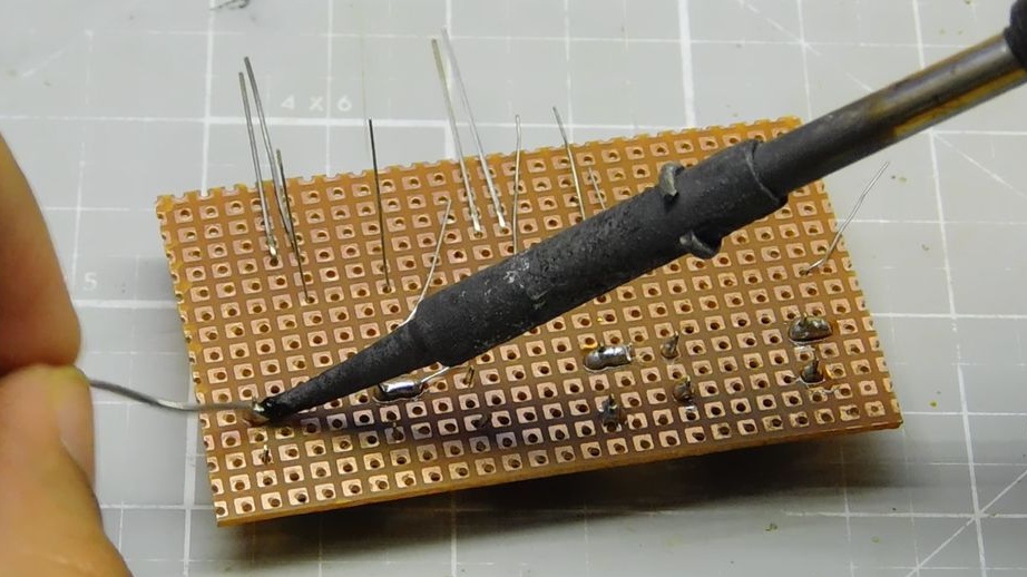
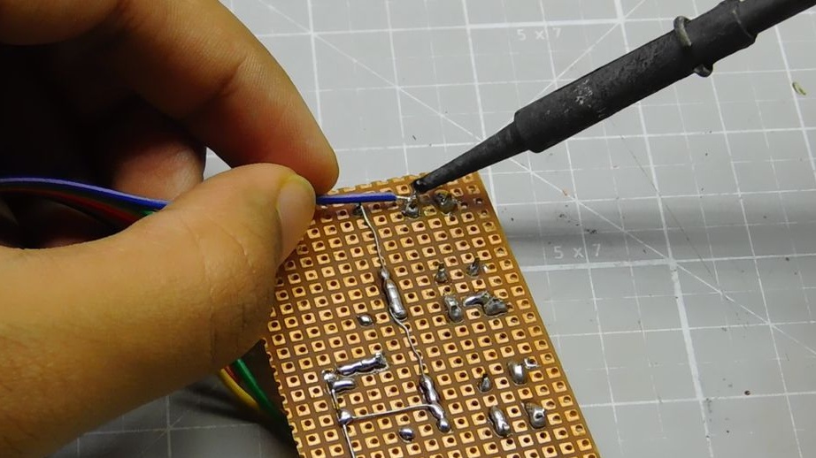
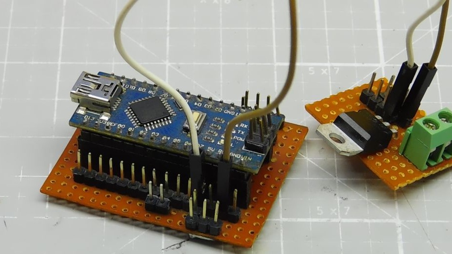
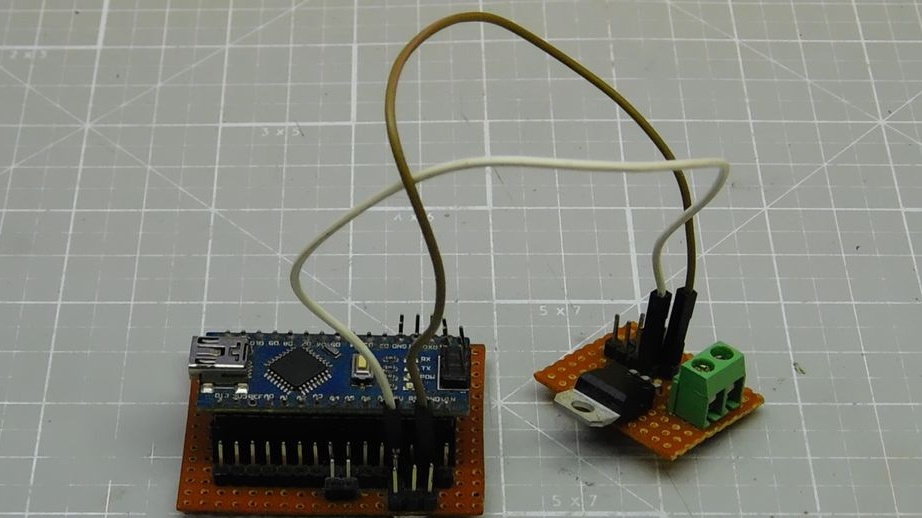
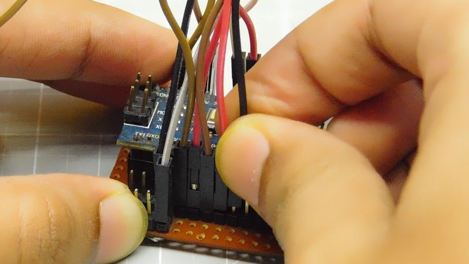
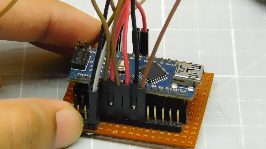
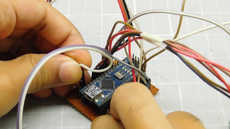
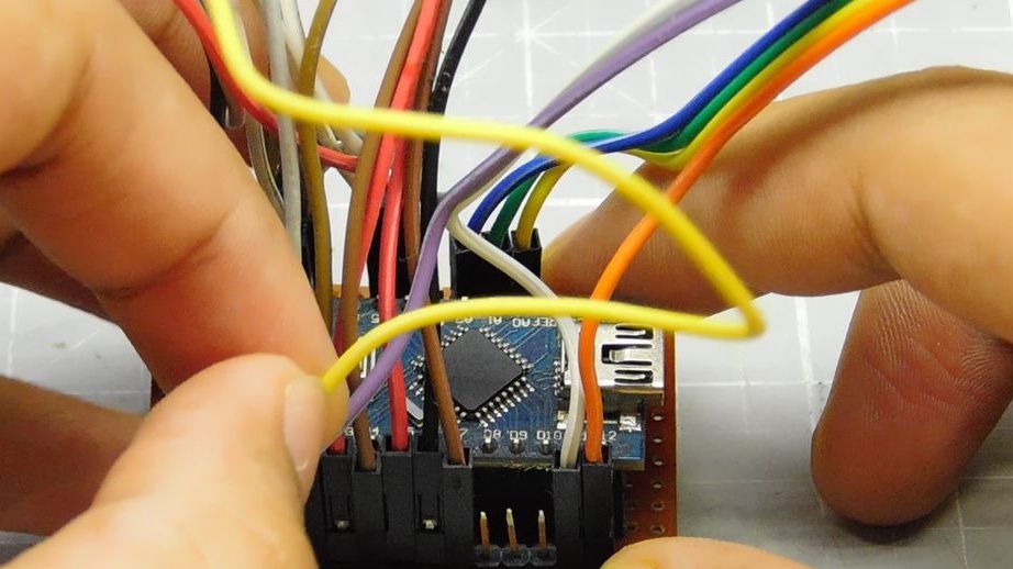
Step two: circuit board
Mounts pin connectors for mounting an Arduino on a circuit board. Adds in parallel additional connectors 5V, Gnd, A4 (SDA) and A5 (SCL).
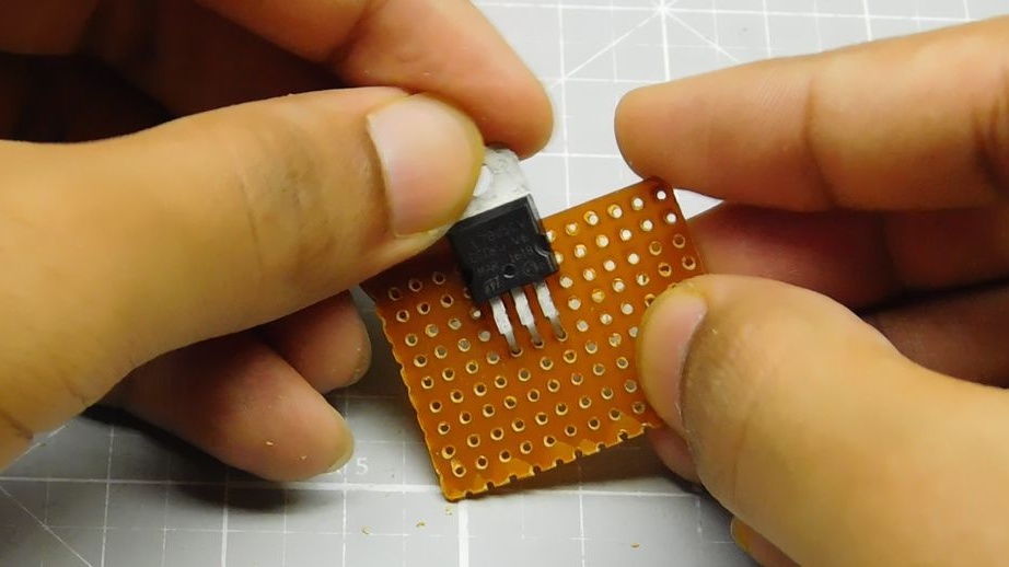
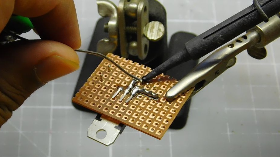
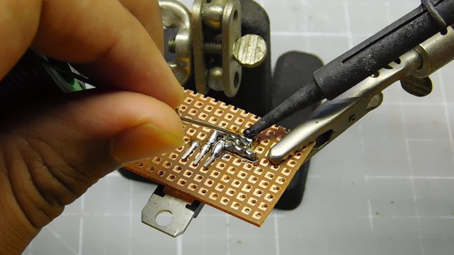
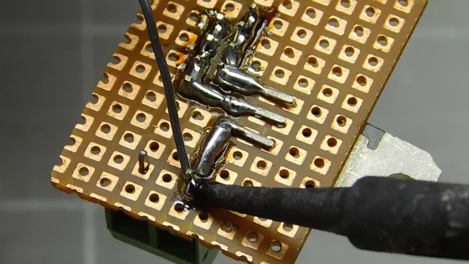
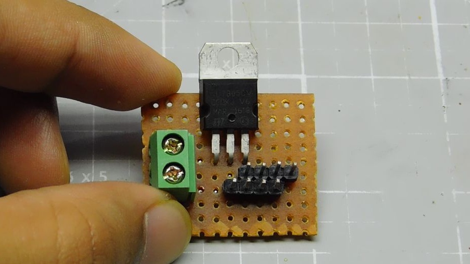
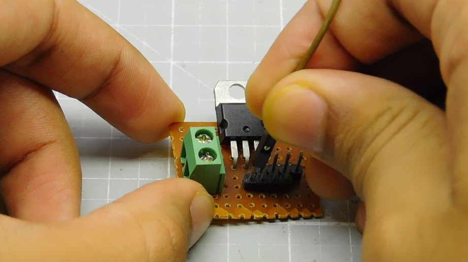
Step Three: Voltage Regulator
According to the circuit, it collects a voltage regulator on the L7805.
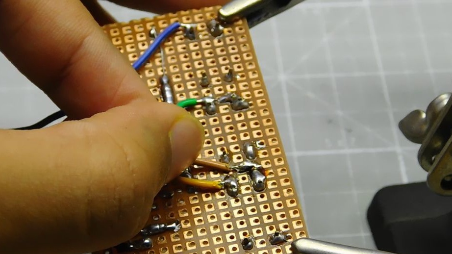
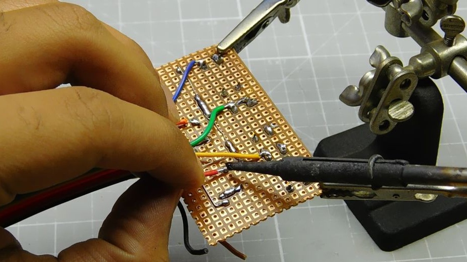
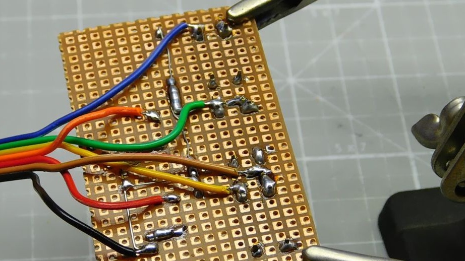
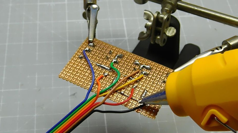
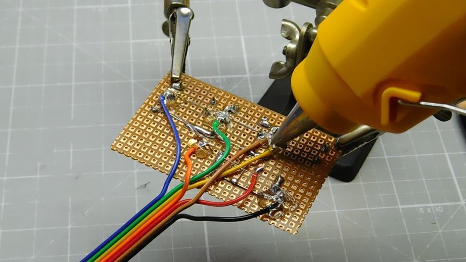
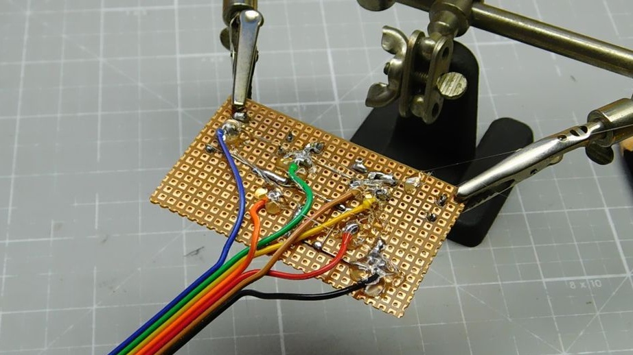
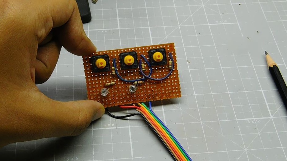
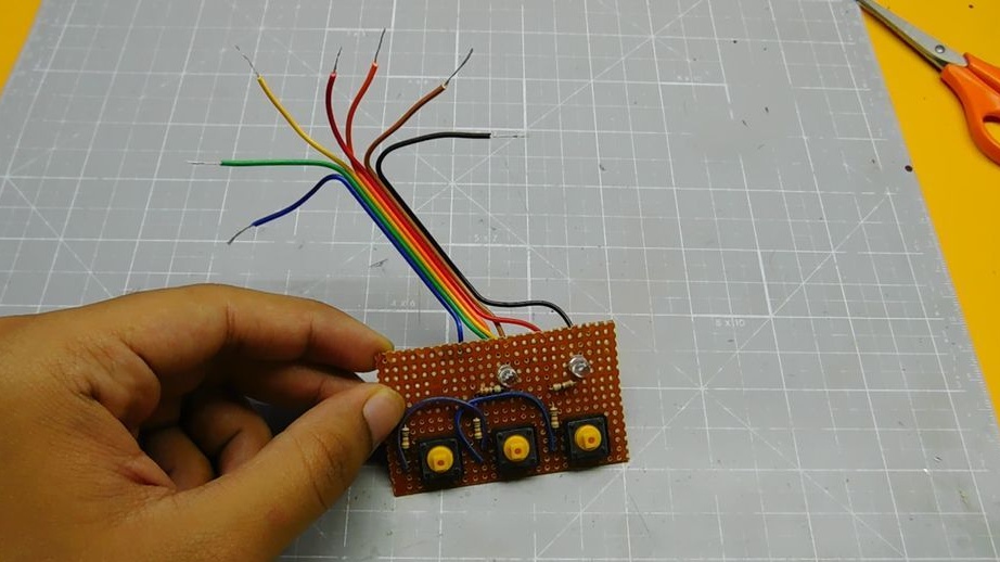
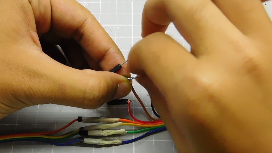
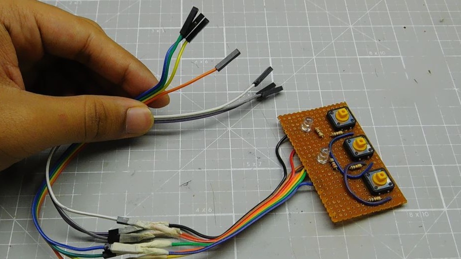
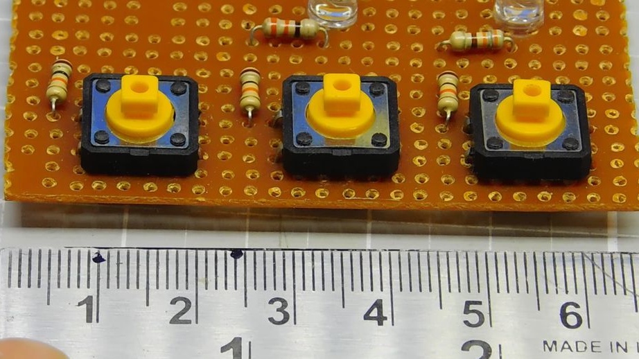
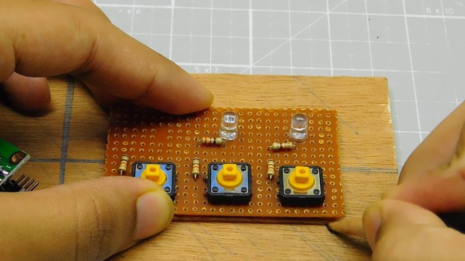
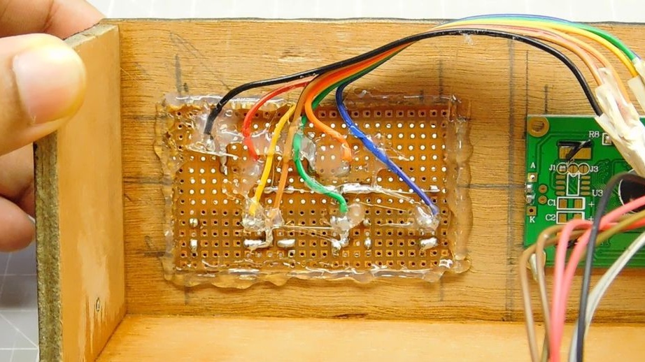
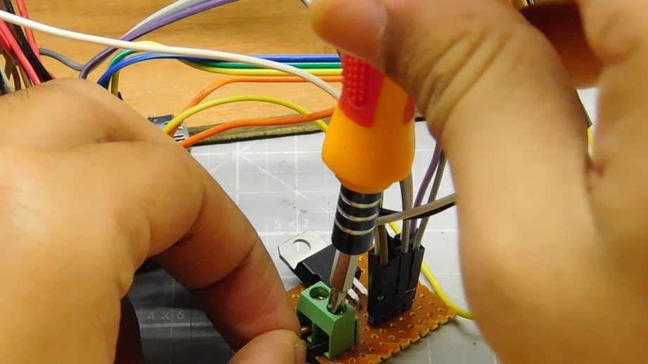
Step Four: Buttons and LEDs
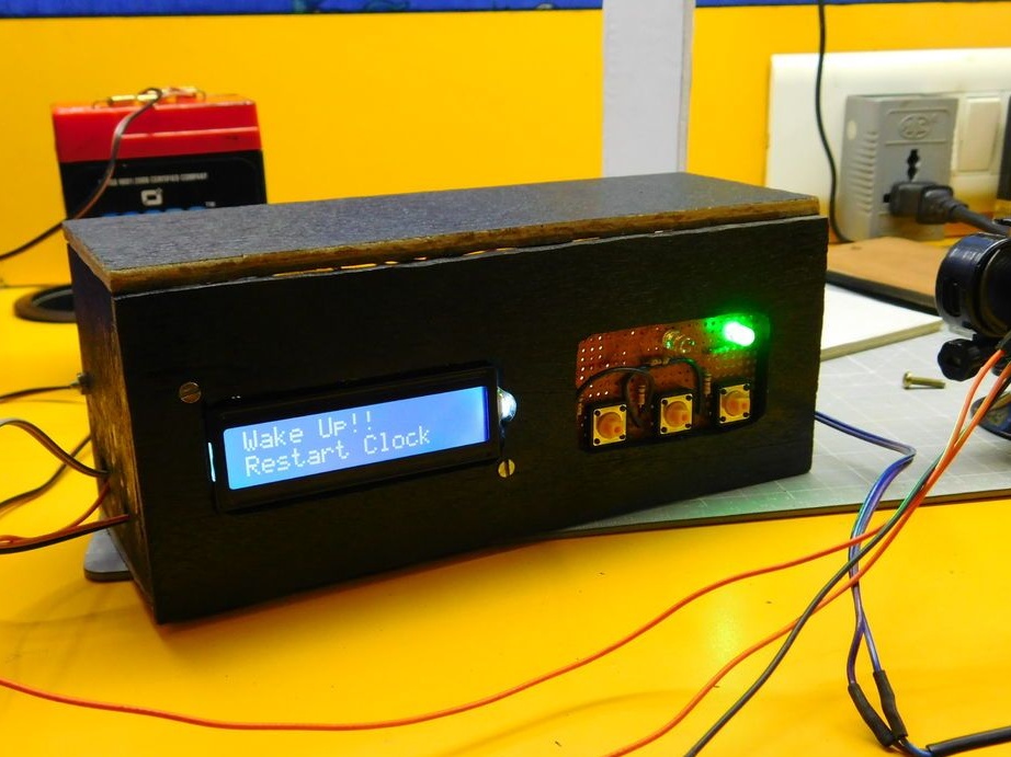
The alarm clock has three buttons. The first button allows you to enter the time and alarm setting mode. The second and third buttons set the time of the clock and the alarm. Also, 2 and 3 buttons turn off the alarm. Mounts parts on the board. 2 and 3, the button is mounted under the LEDs.
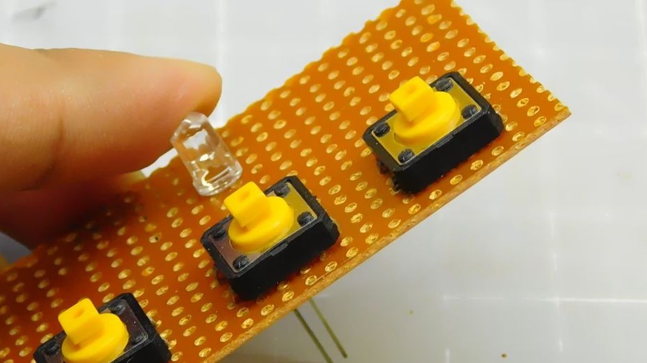
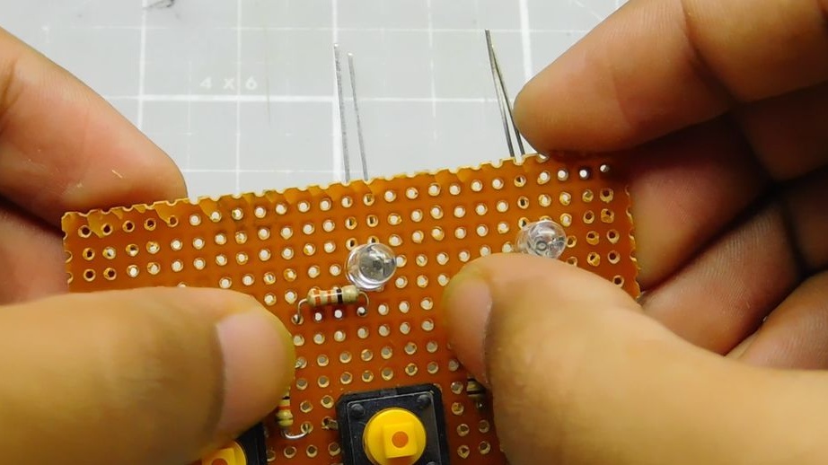
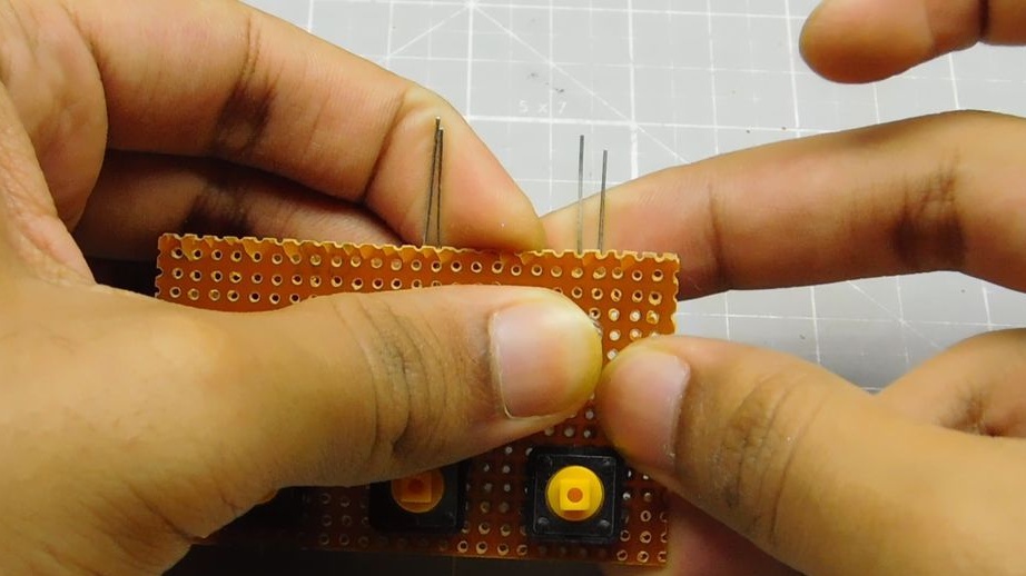
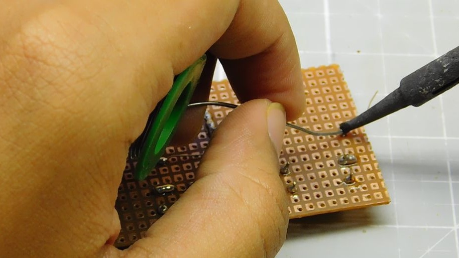
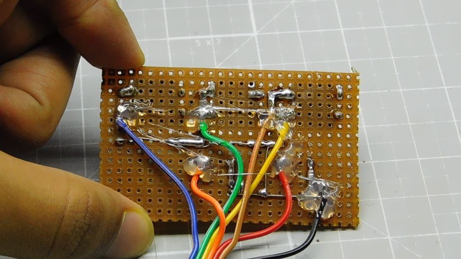
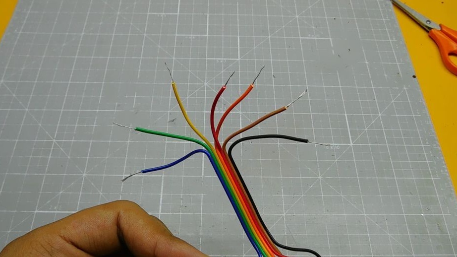
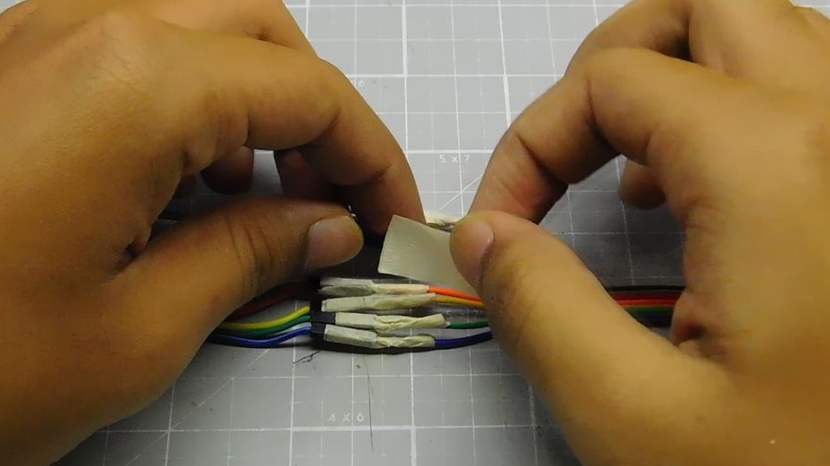
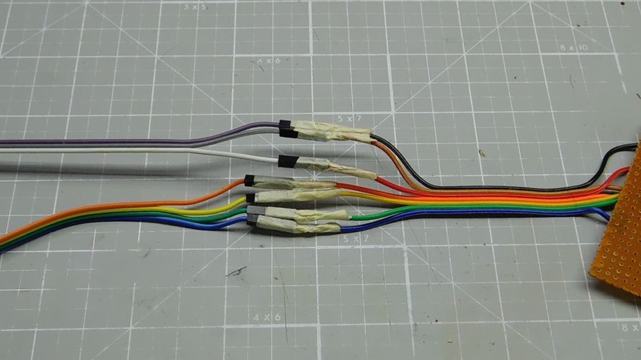
Then it solders to the contact of the LEDs and wire buttons. 330 ohm resistors are soldered to the LED circuit, 10 kΩ resistors to the button circuit. Extends them with jumper wires. Places isolates with electrical tape.
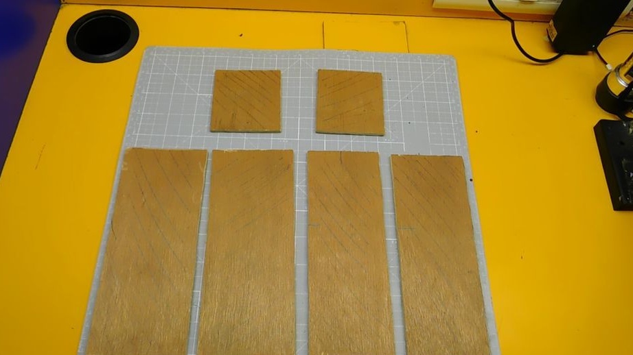
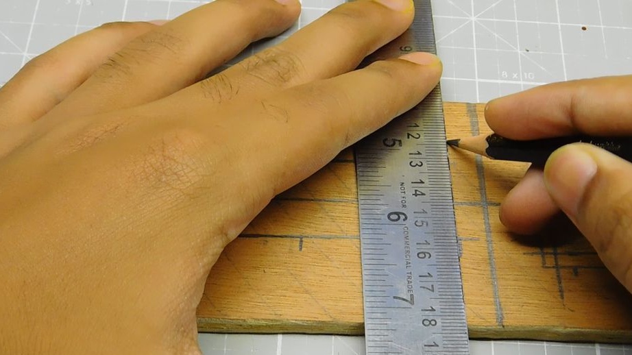
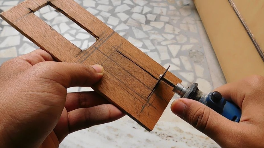
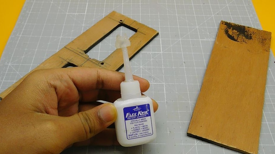
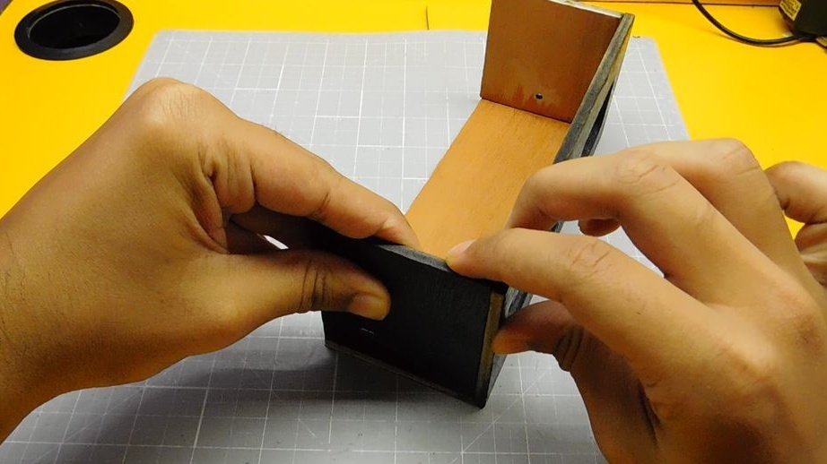
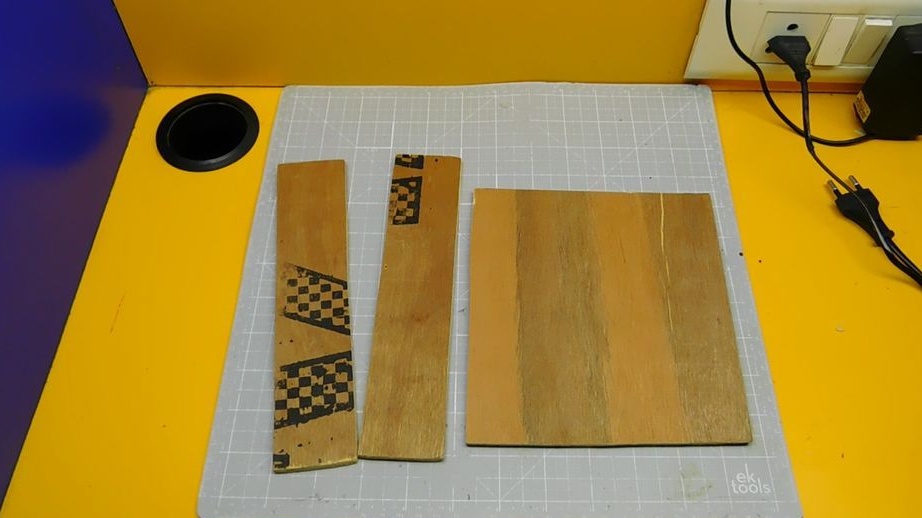
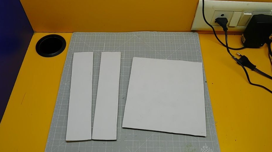
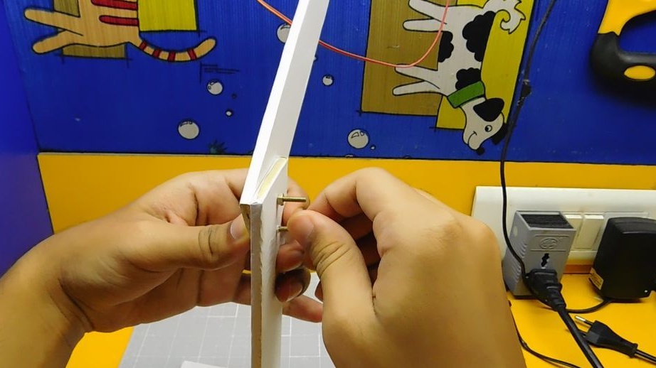
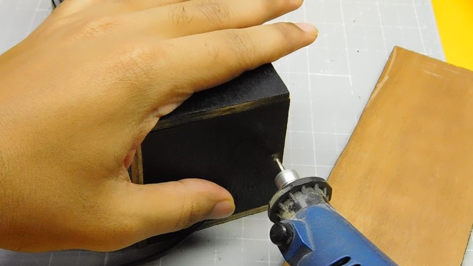
Step Five: Case
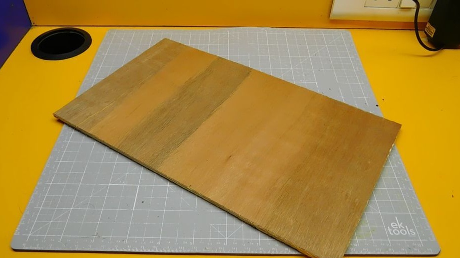
The master makes the body of the alarm clock out of plywood. The entire housing will be housed electronics.
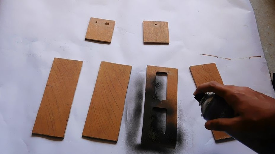
Cuts six parts. Two 19 x 7.5 cm, two 19 x 6.5 cm and two 7.5 x 6.5 cm.
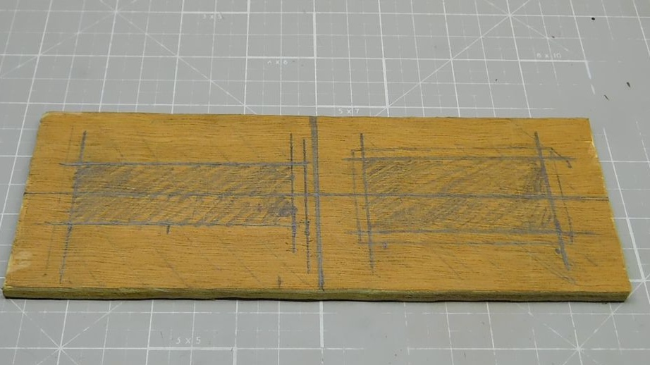
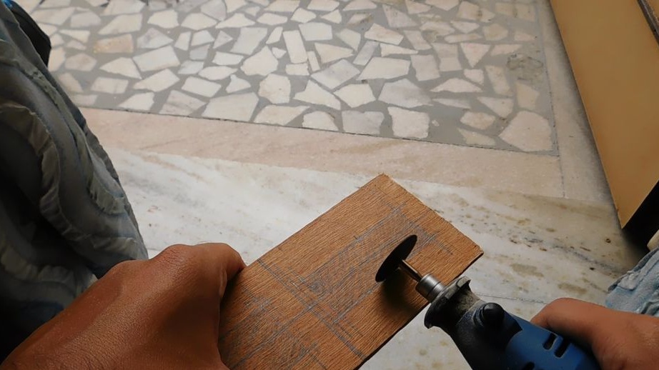
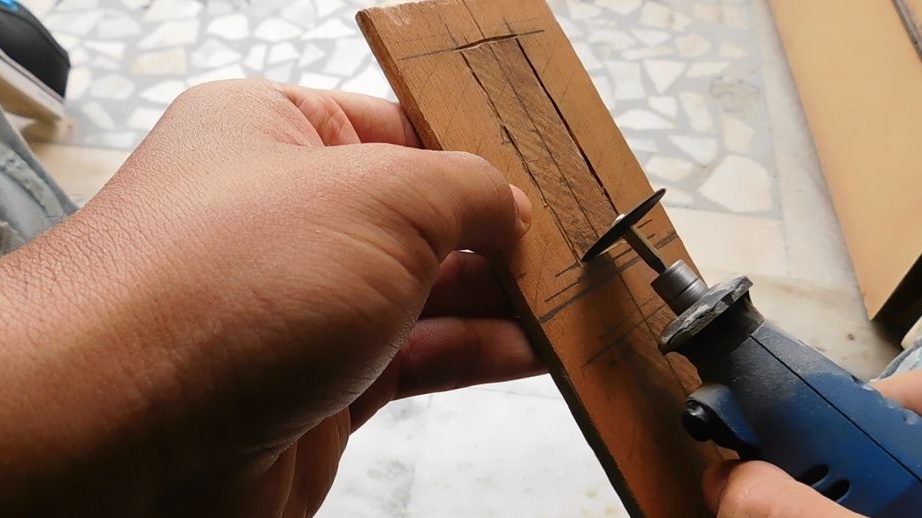
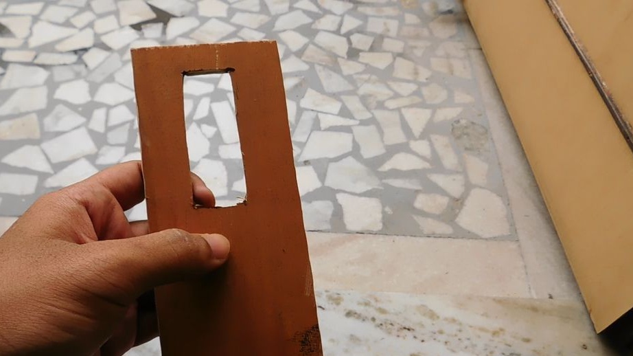
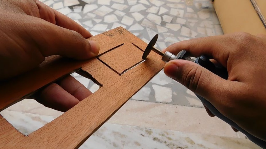
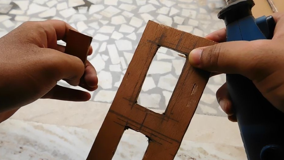
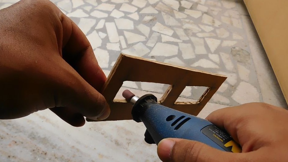
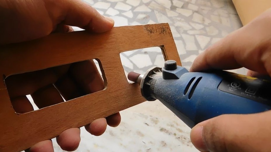
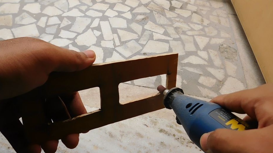
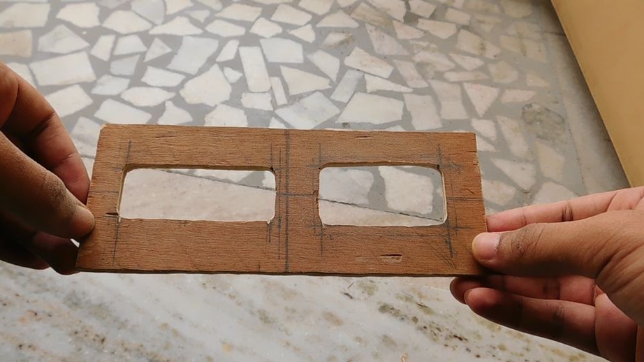
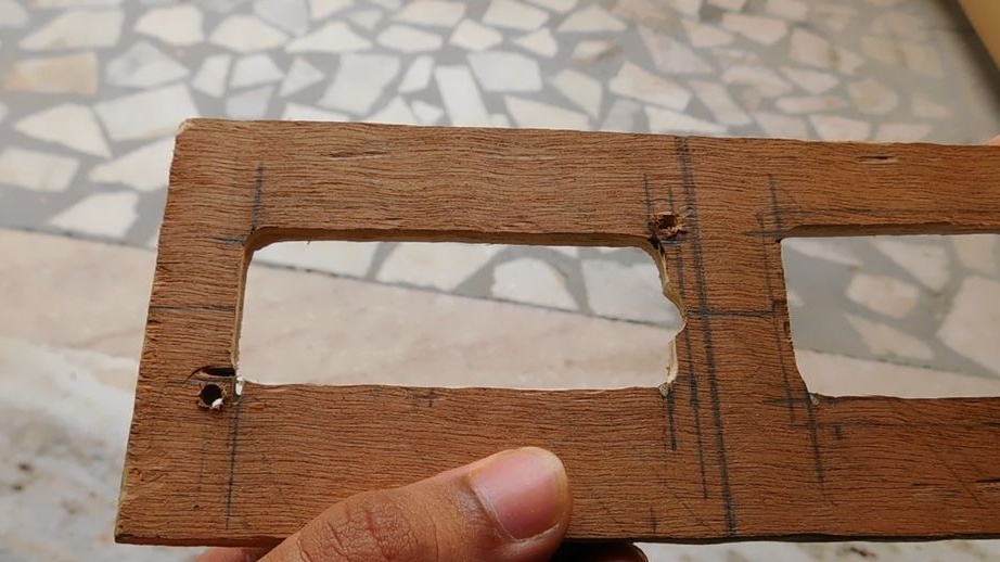
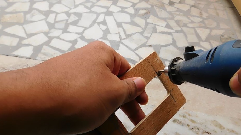
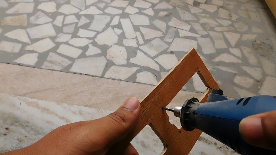
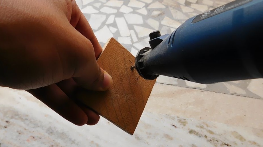
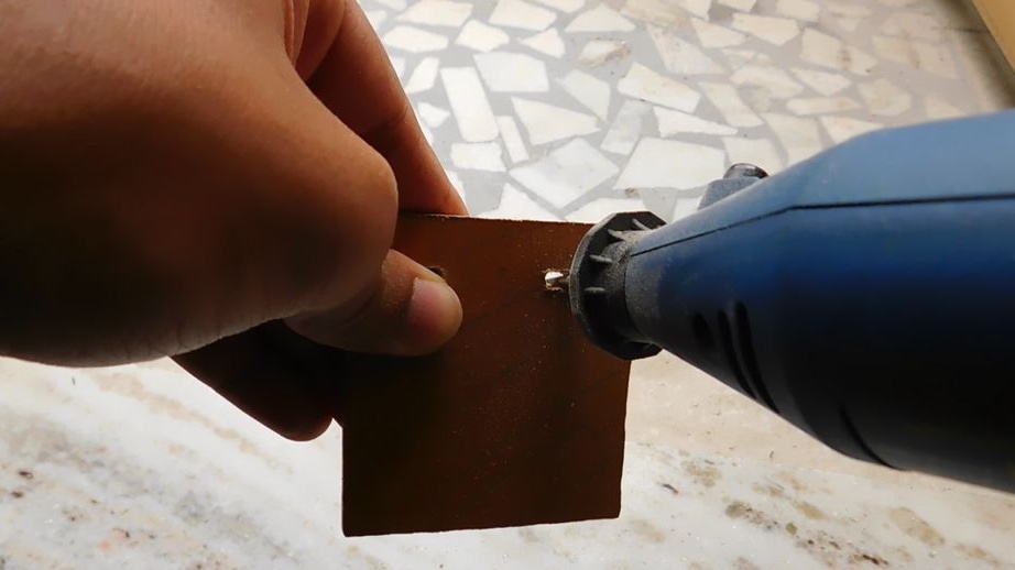
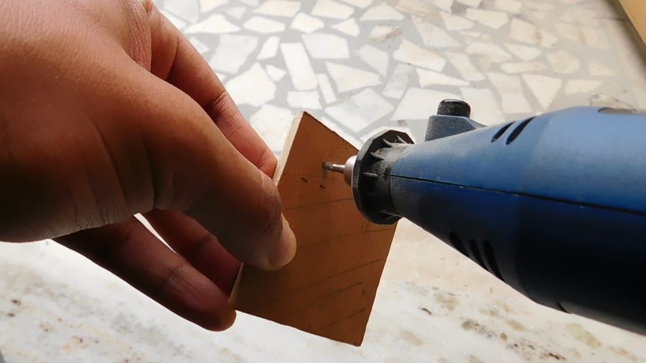
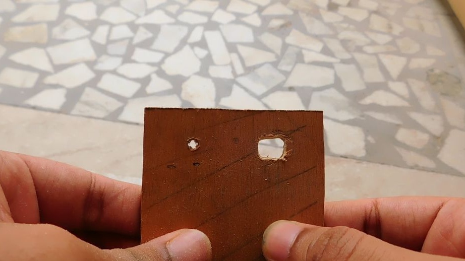
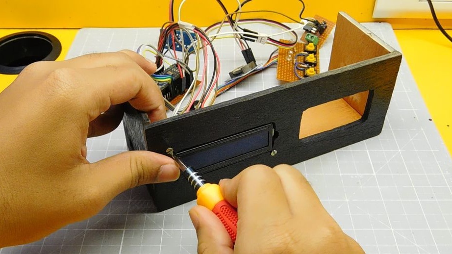
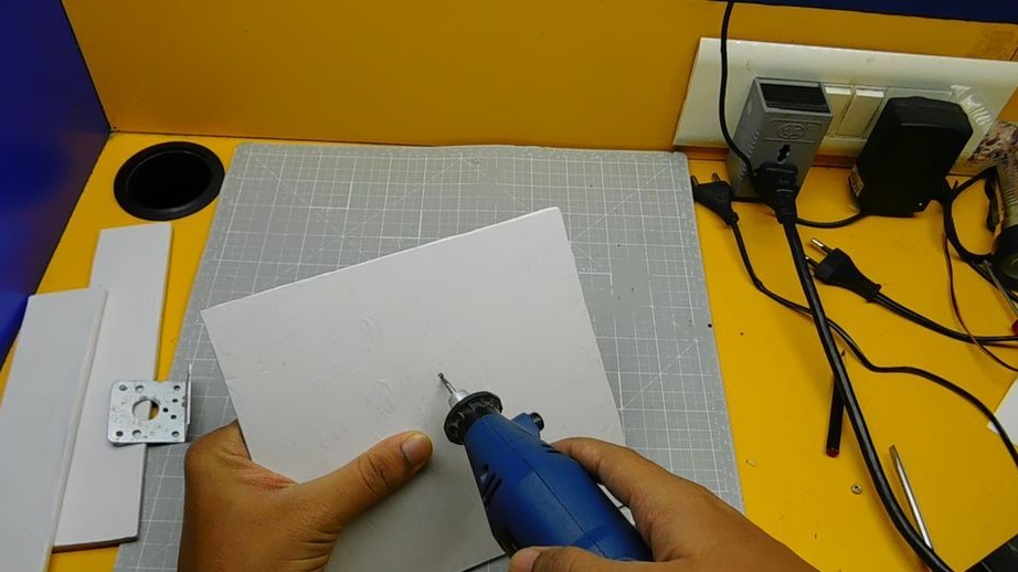
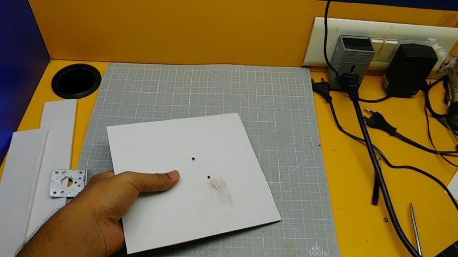
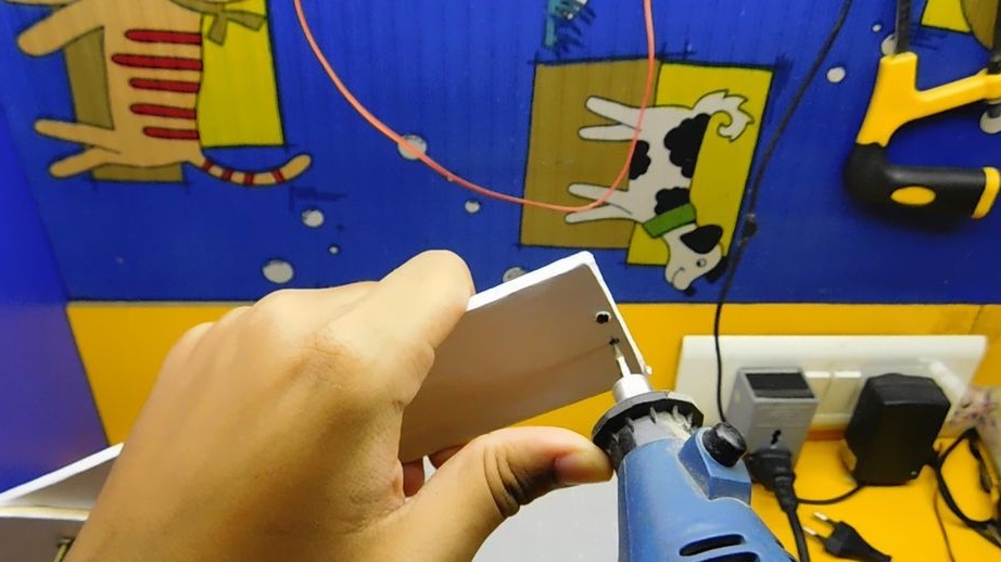
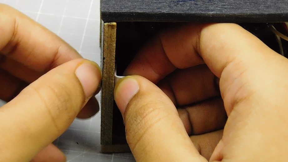
On the front panel marks and cuts out openings for the LCD display and buttons.

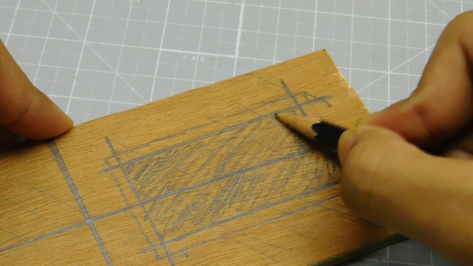

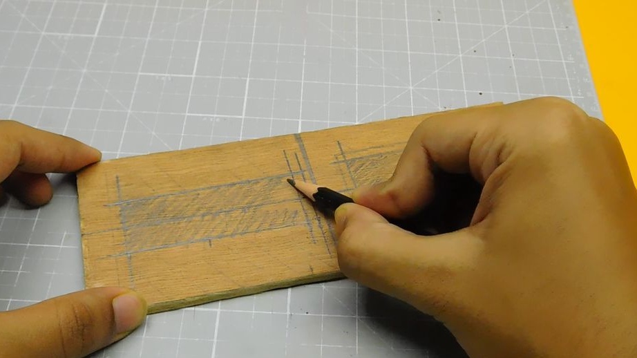
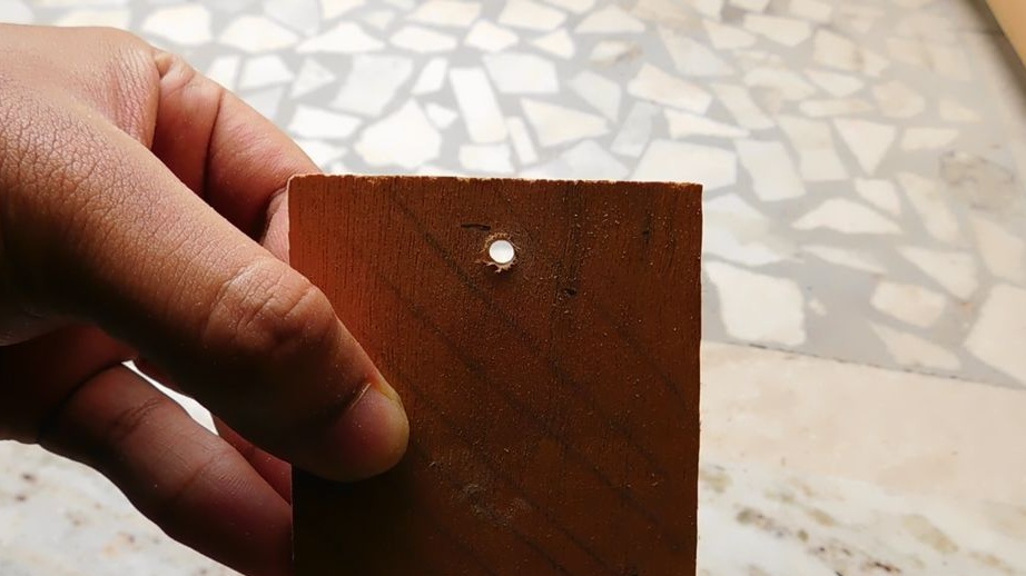
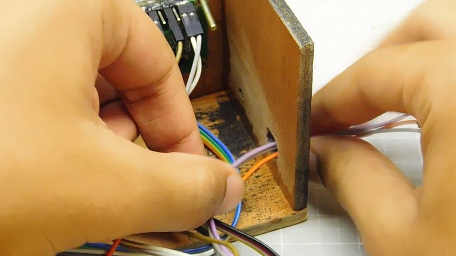
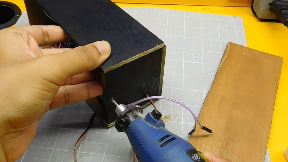
On the right panel, drills a hole for the wire. On the left panel, drills two holes for the wires.
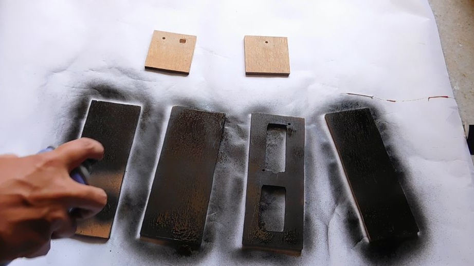
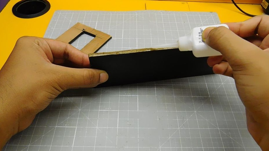
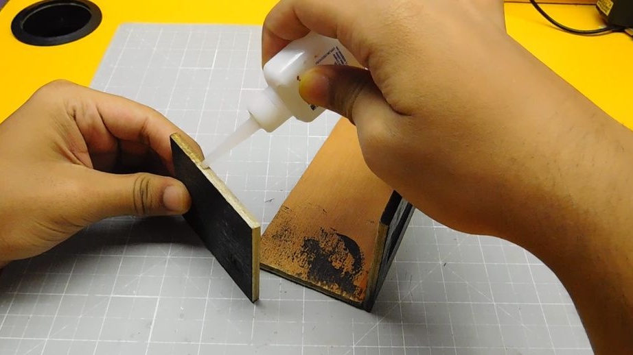
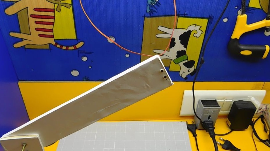
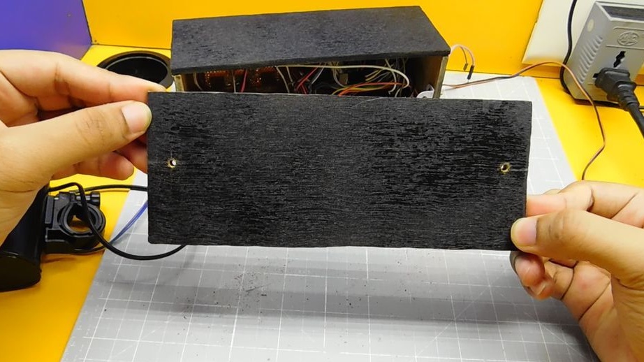
Treats edges with sandpaper. Covers the front surfaces of panels with paint.

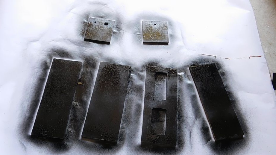
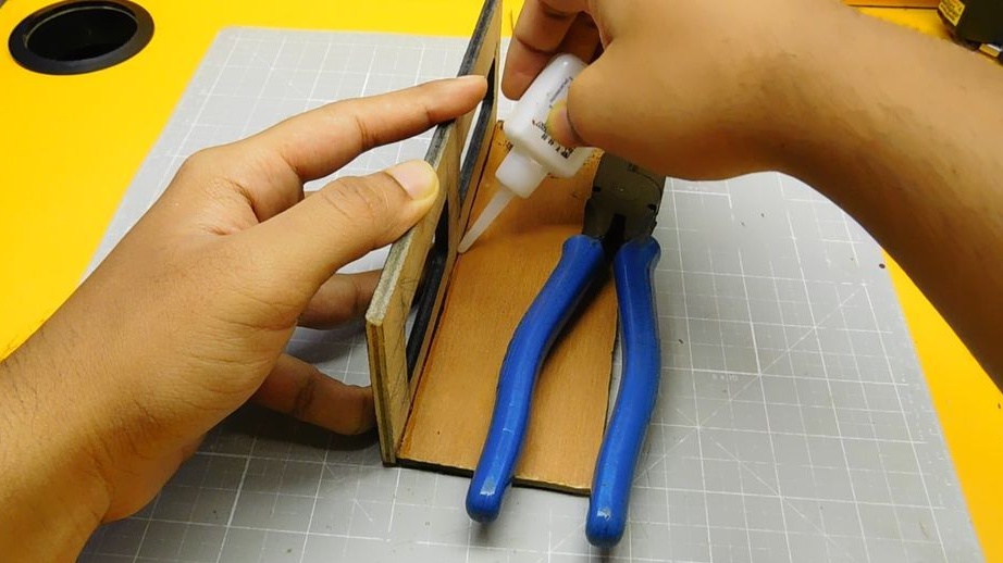
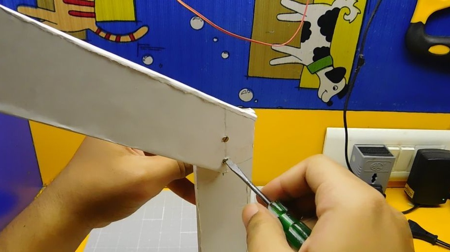
Glues four sides of the body.
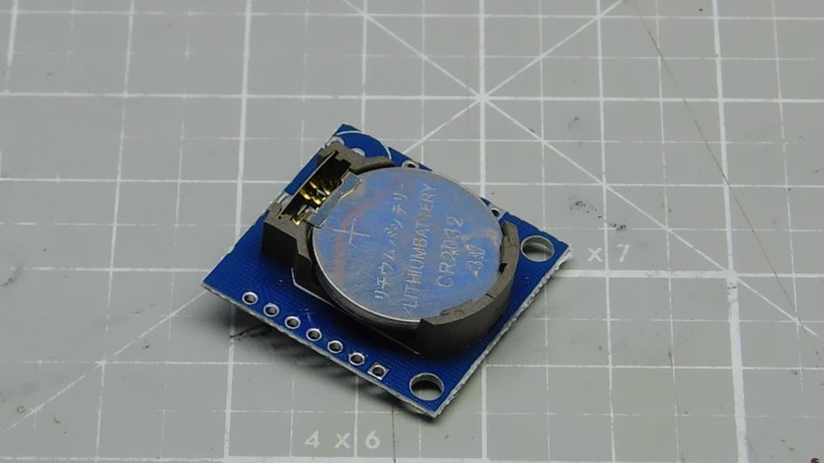
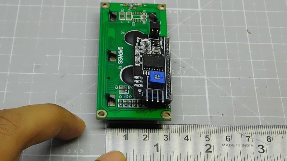
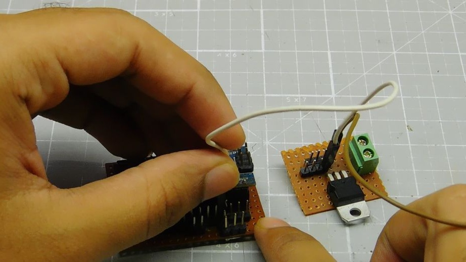
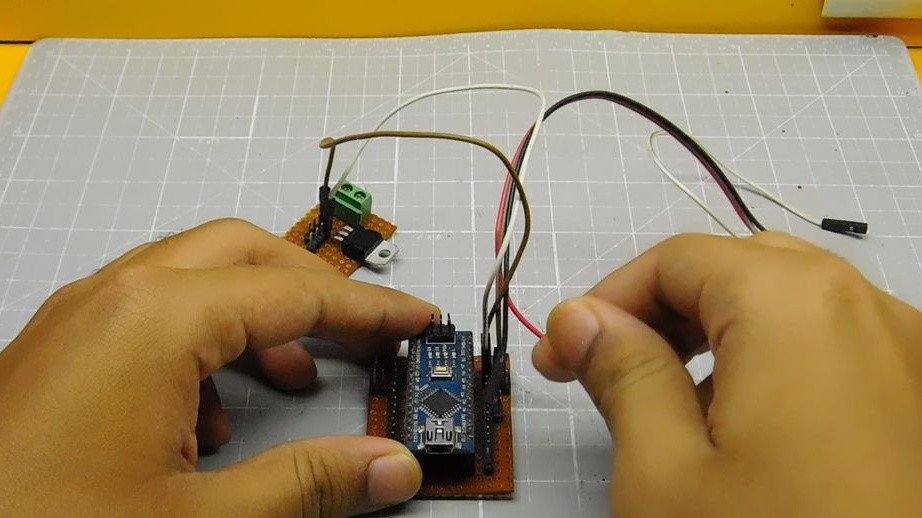
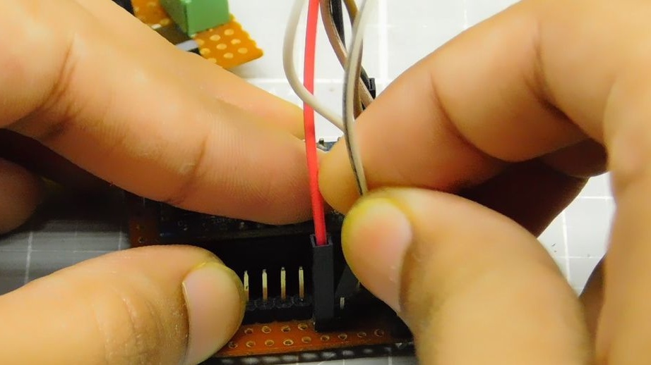
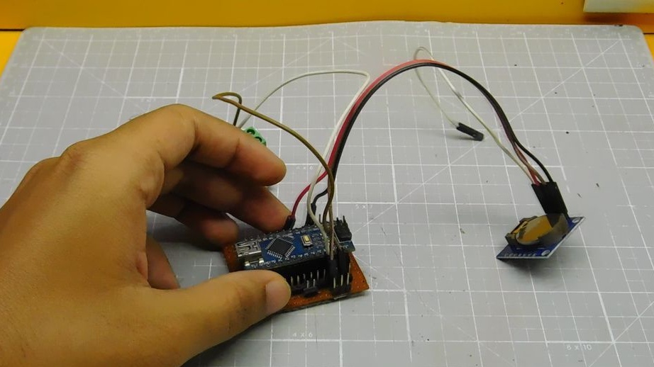
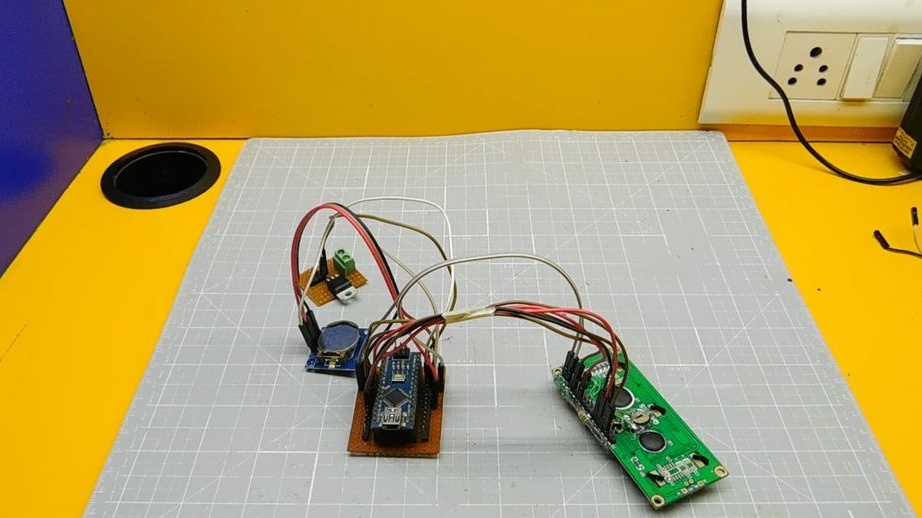
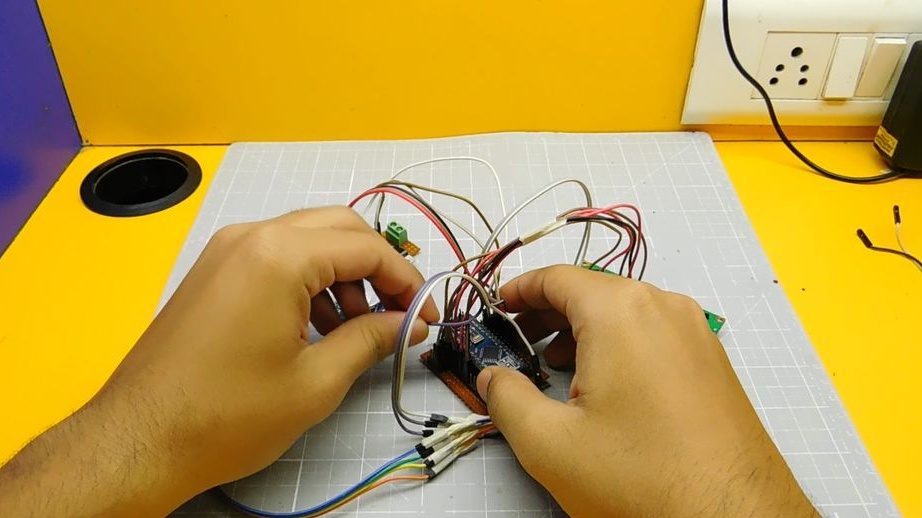
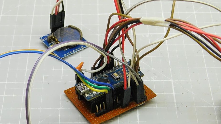
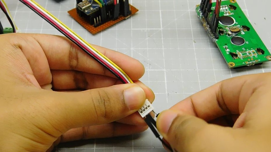
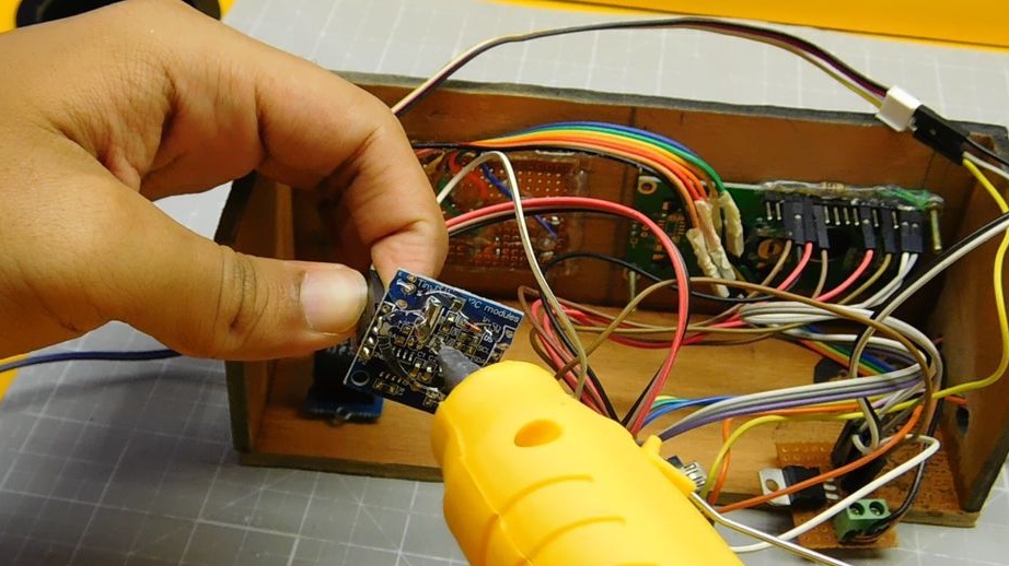
Step Six: Connect the RTC Module and Regulator
Connects the RTC I2C clock module to Arduino:
Module Arduino
Vcc ---- 5v
Gnd ---- gnd
SDA ---- A4 (analog output 4)
SCL ---- A5 (analog output 5)
Connects voltage regulator:
Regulator Arduino
5v Out ---- 5v
Gnd ---- gnd

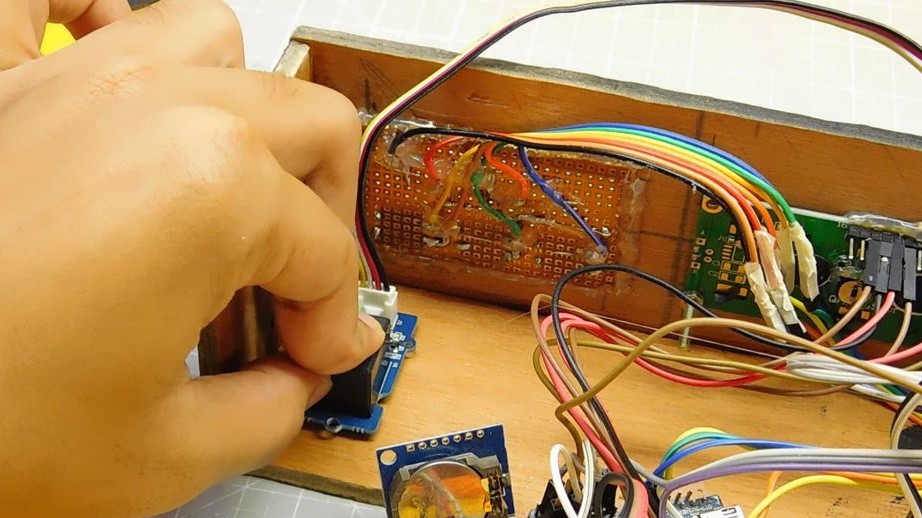
Step six: mounting the main circuit
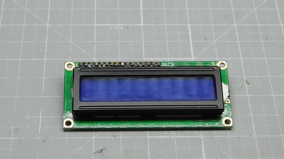
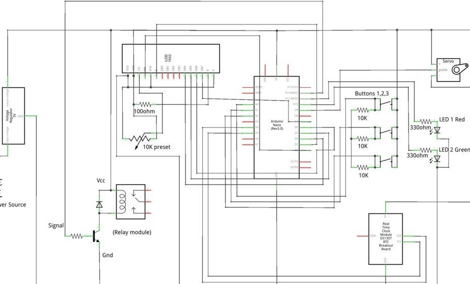
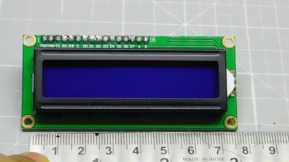
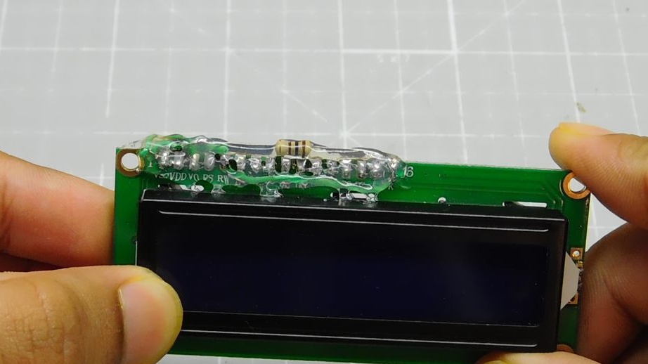
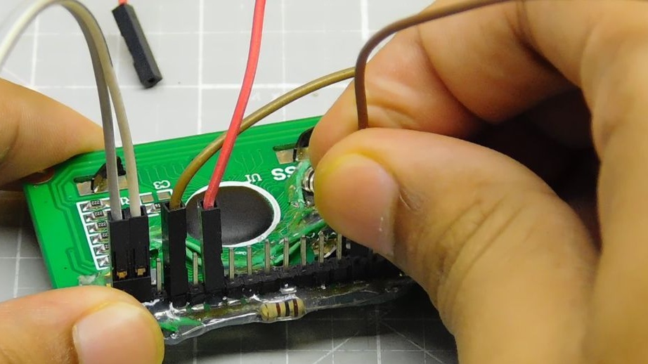
For his project, the master chose a 16-pin LCD. 8 contacts are connected to Arduino.
LCD - Arduino
1 ---- Gnd
2 ---- 5v
4 ---- D2
6 ---- D3
11 ---- D4
12 ---- D5
13 ---- D6
14 ---- D7
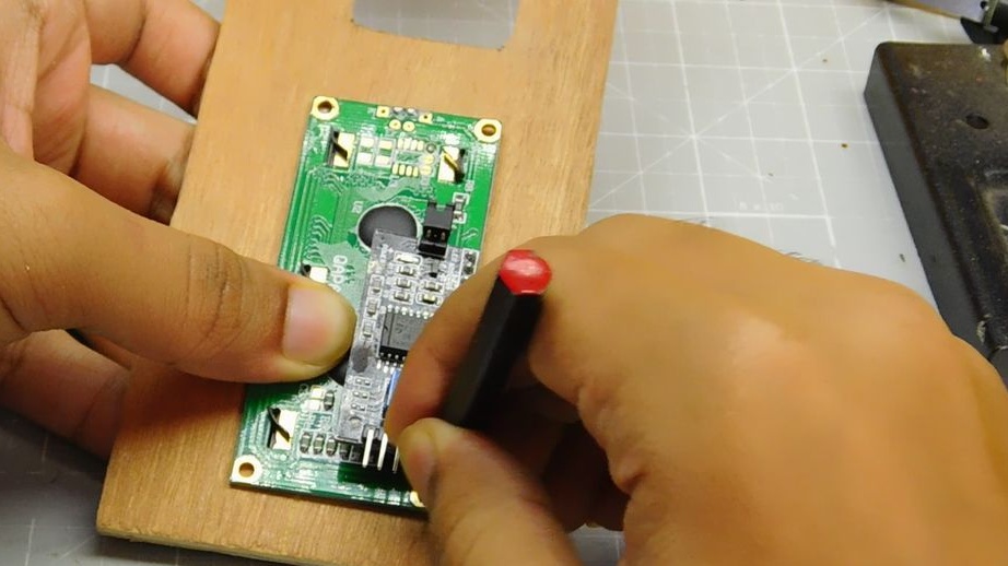
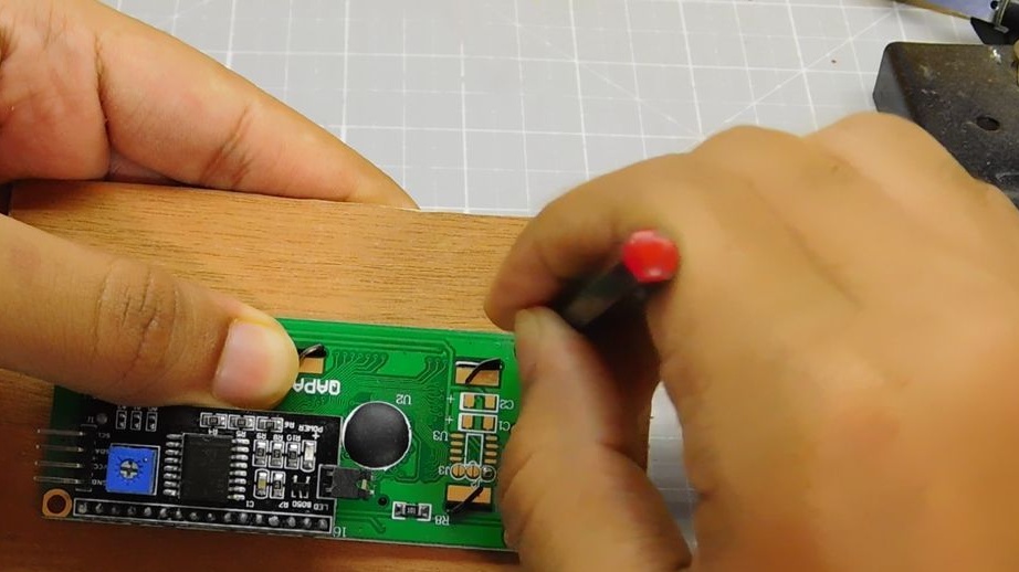
Contacts 1, 5, 16 are connected to Gnd, contacts 2, 15 to plus 5V. Pin 15 (backlight) is soldered through a 100 ohm resistor. The master solders the left leg of the potentiometer (to adjust the brightness of the backlight) to pin 1, the right to pin 2, and the middle to pin 3 of the LCD. After installation, fill the contact pad with hot glue.
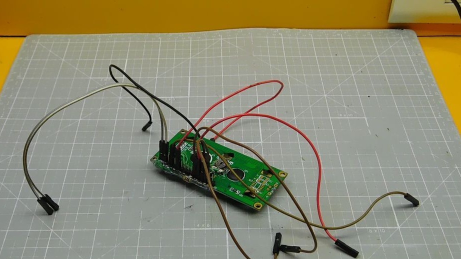
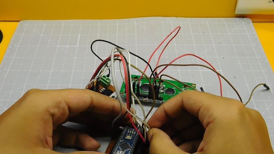
Next, connect the button board.
Plata Arduino
Vcc ---- 5v
Gnd ---- gnd
LED 1 ---- D10
LED 2 ---- D11
Button 1 ---- A0
Button 2 ---- A1
Button 3 ---- A2
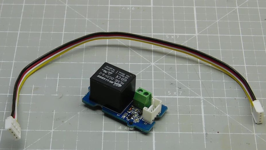
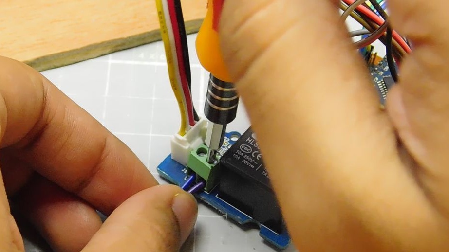
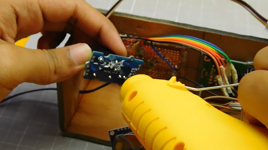
Relay module.
Vcc ---- 5v on arduino
Gnd ---- gnd
Signal ---- D12
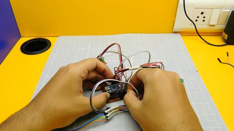
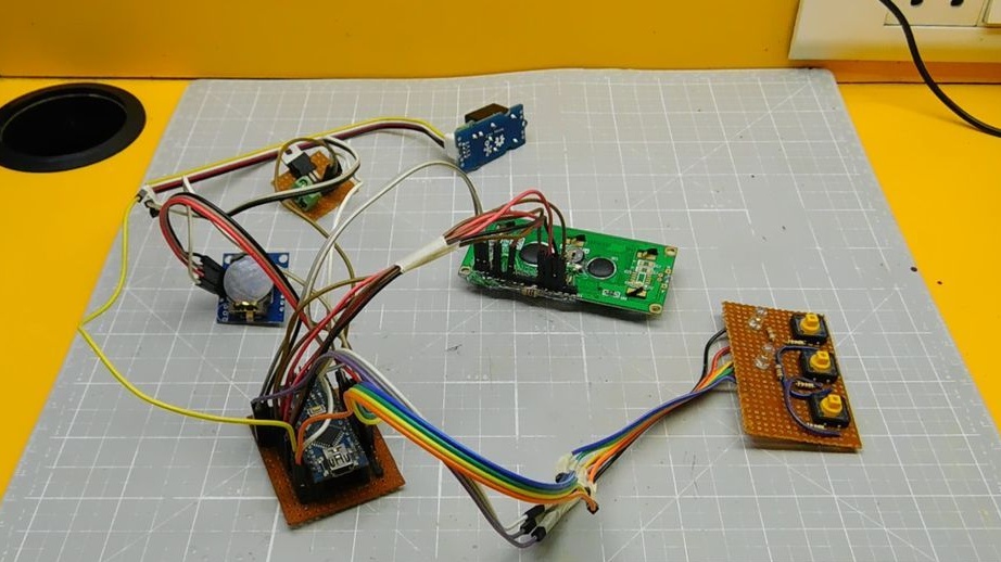
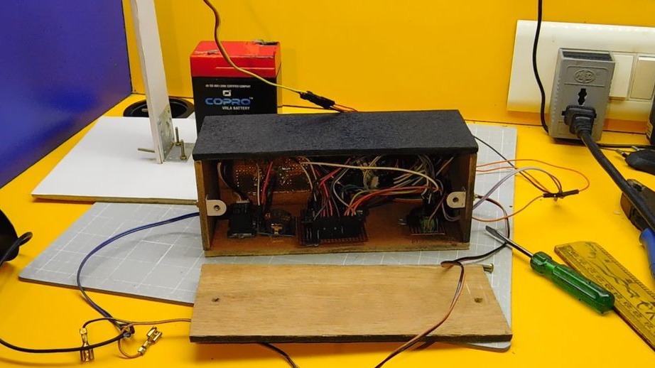
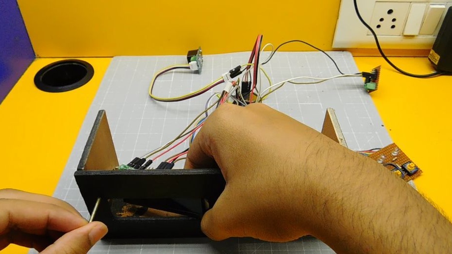
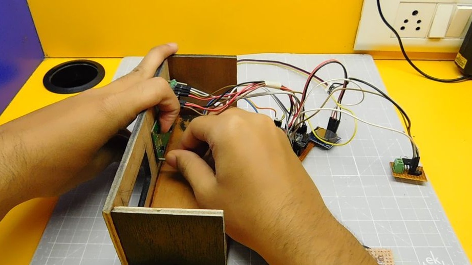
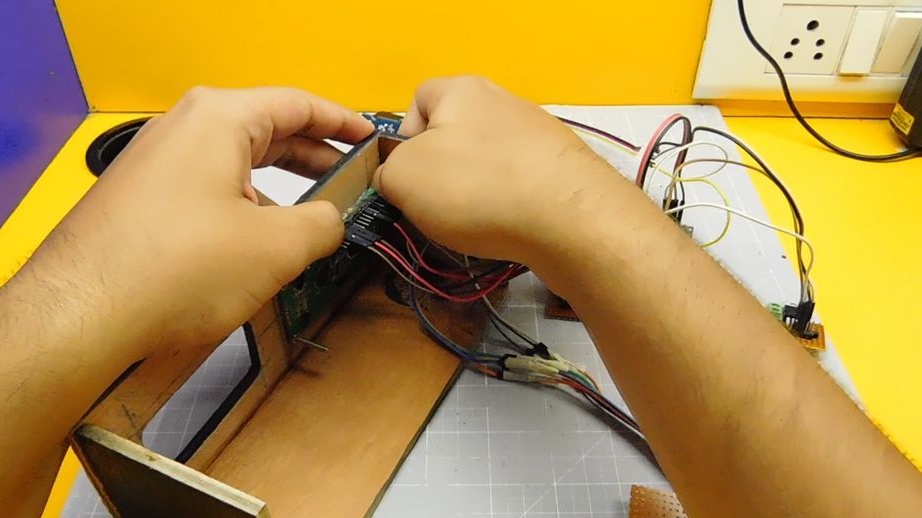
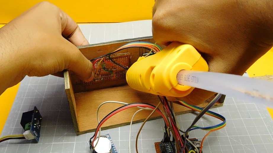
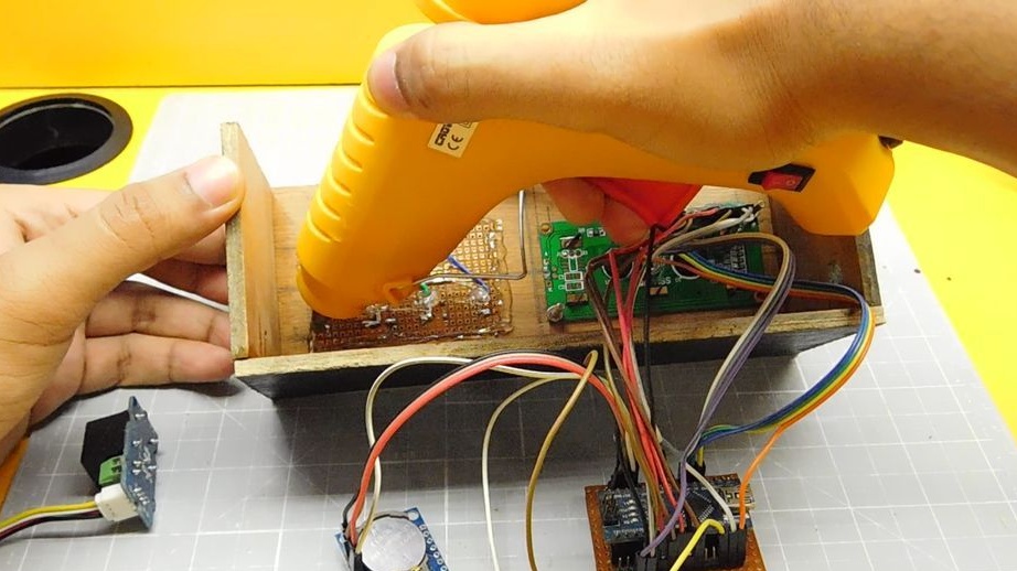
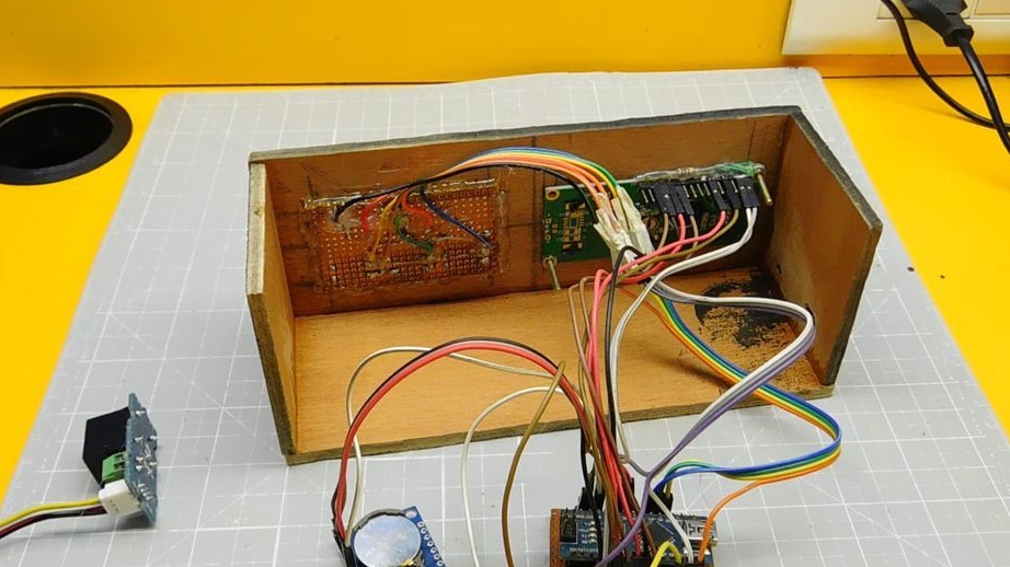
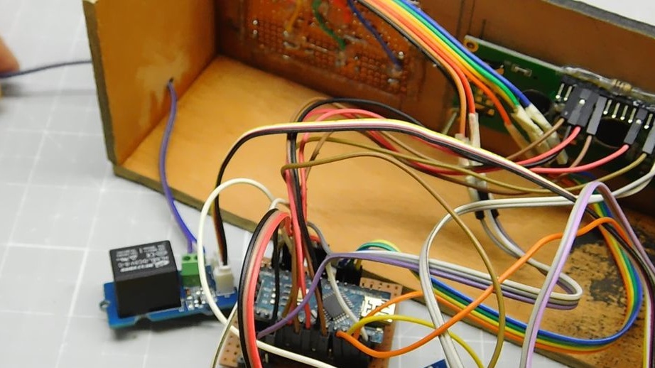
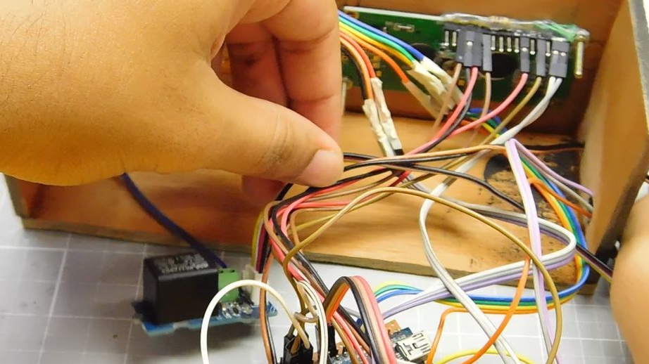
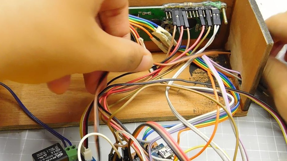
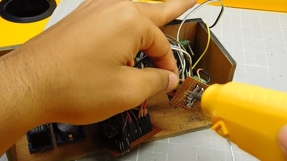
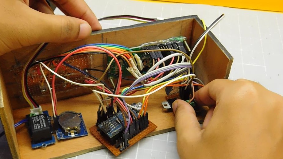
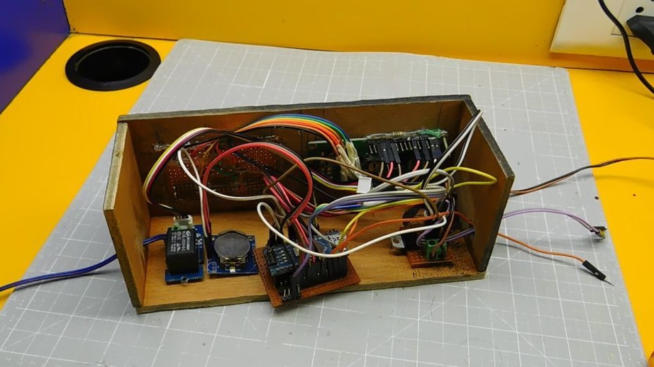
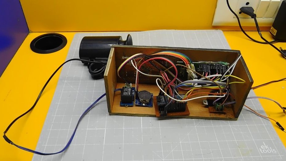
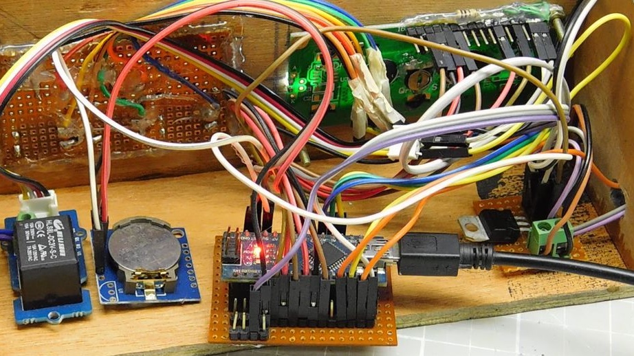
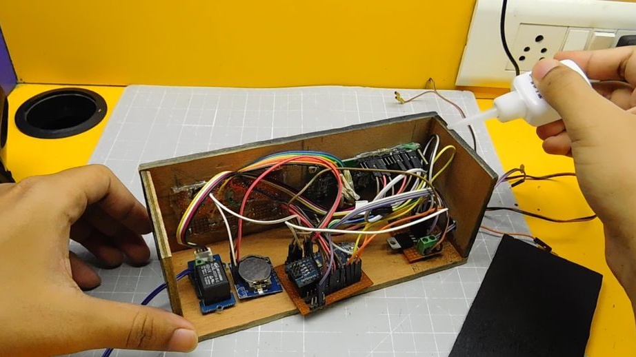
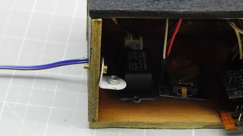
Seventh step: assembly
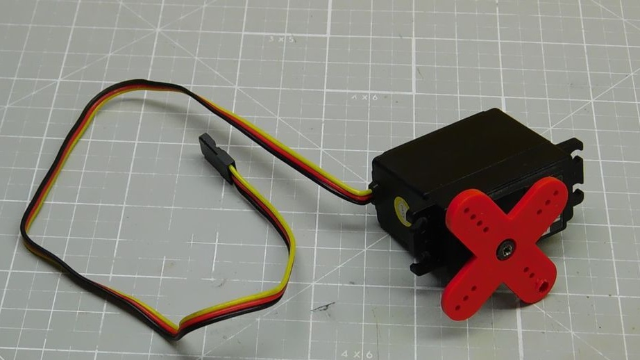
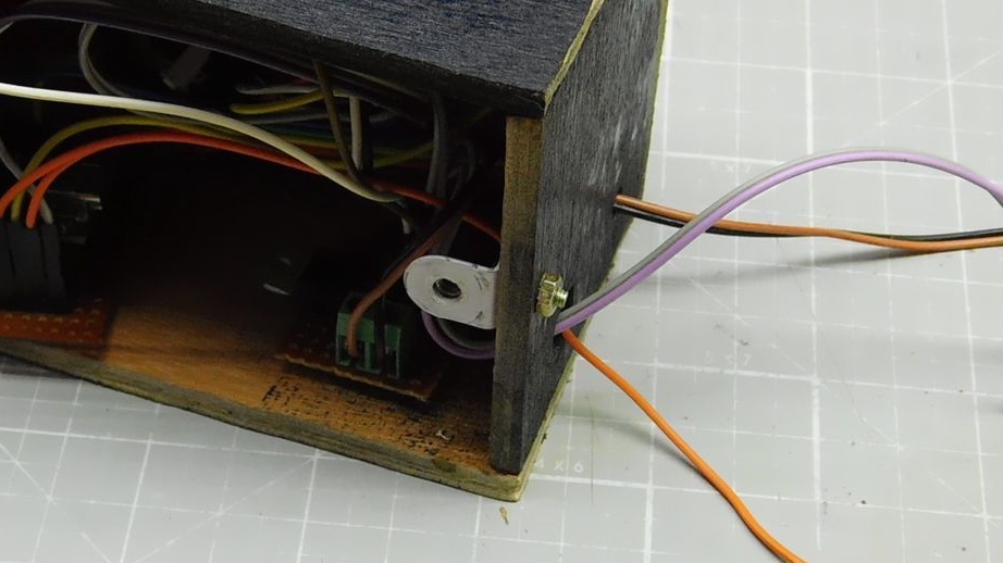
Next, the master installs all the electronic parts in the box. Secures the display, Arduino, relay. To connect a bicycle signal outputs 2 wires from the relay. For the servomotor, it outputs three wires, 5v, Gnd and D9, from Arduino.

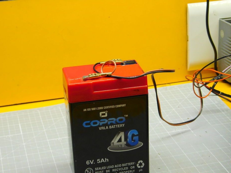
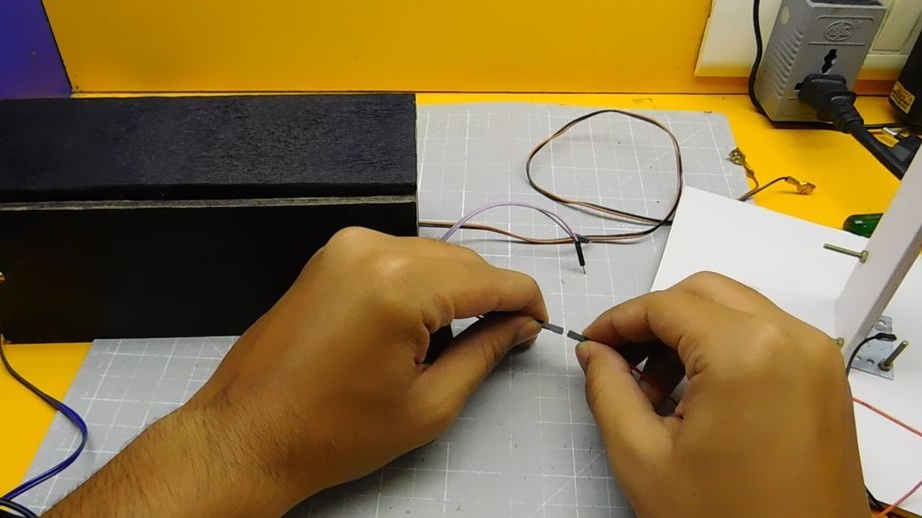
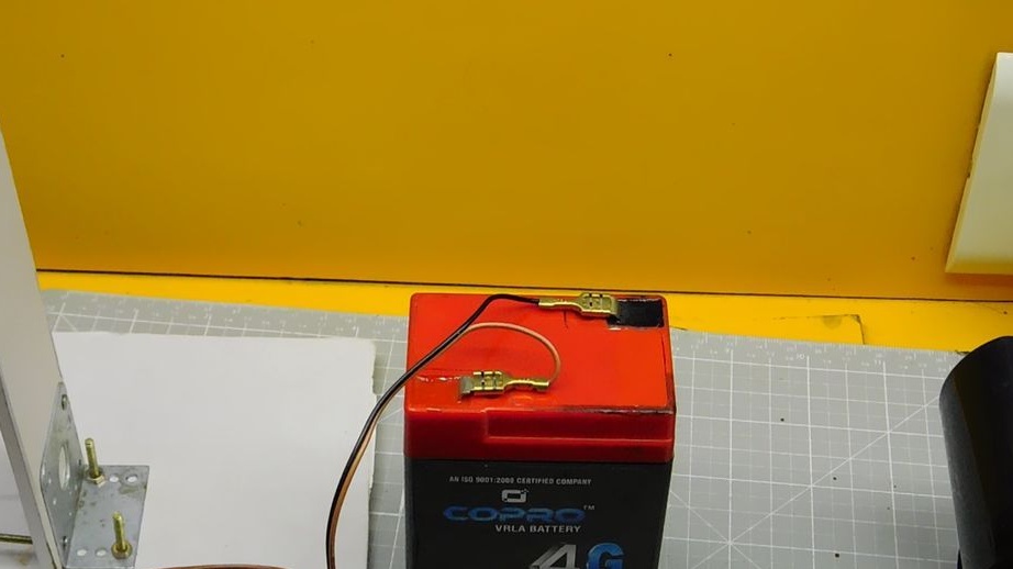
Step Eight: Battery and Signal
Connects signal and battery.
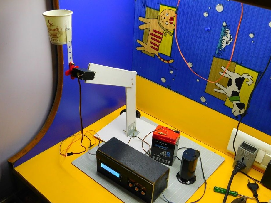
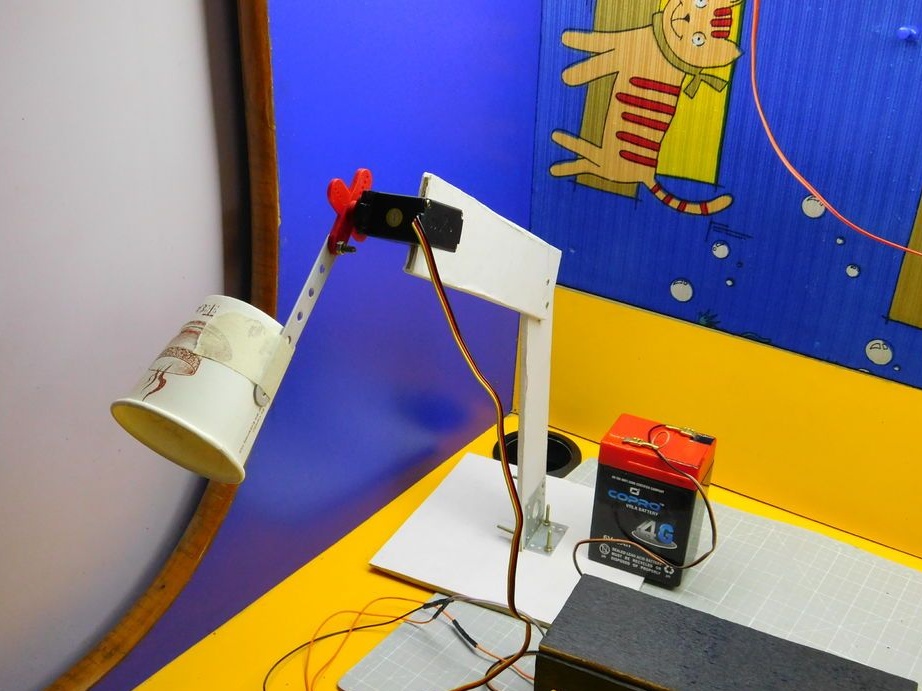
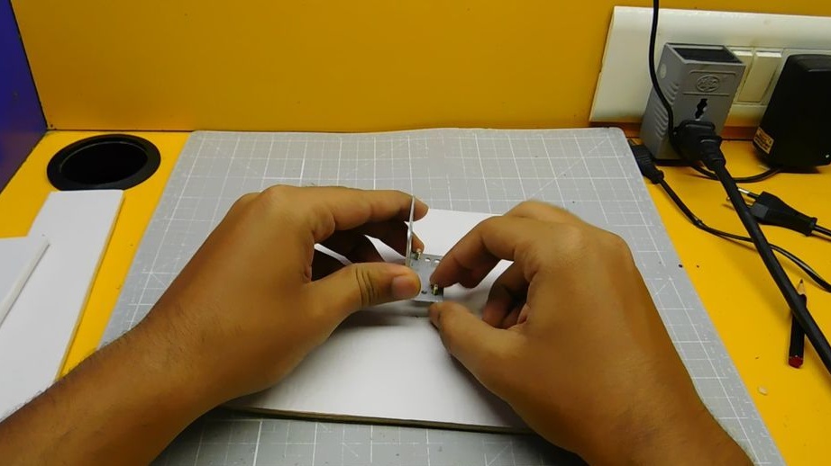
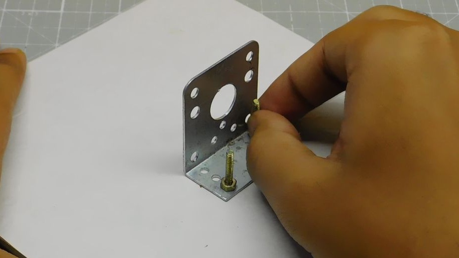
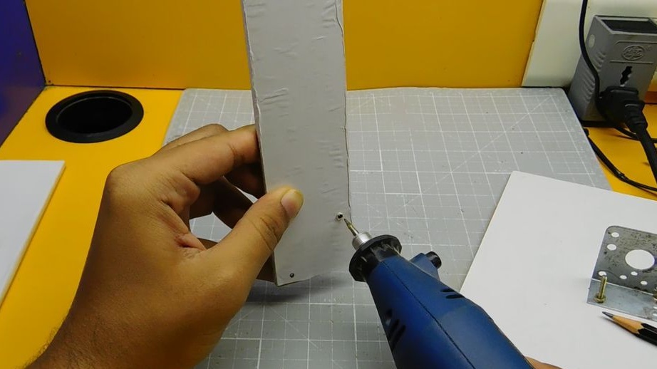
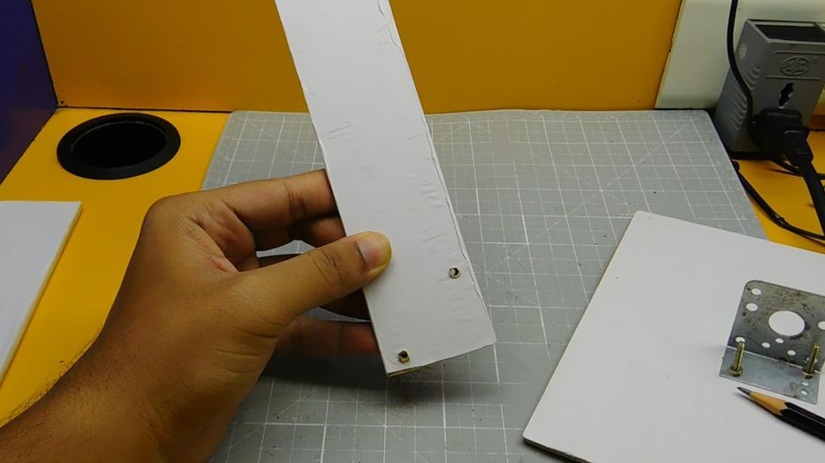
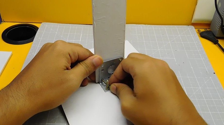
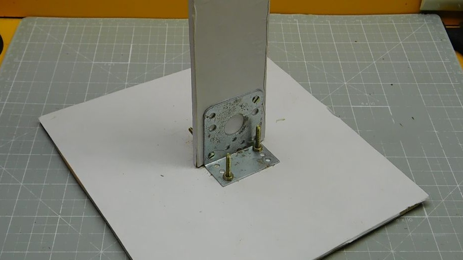
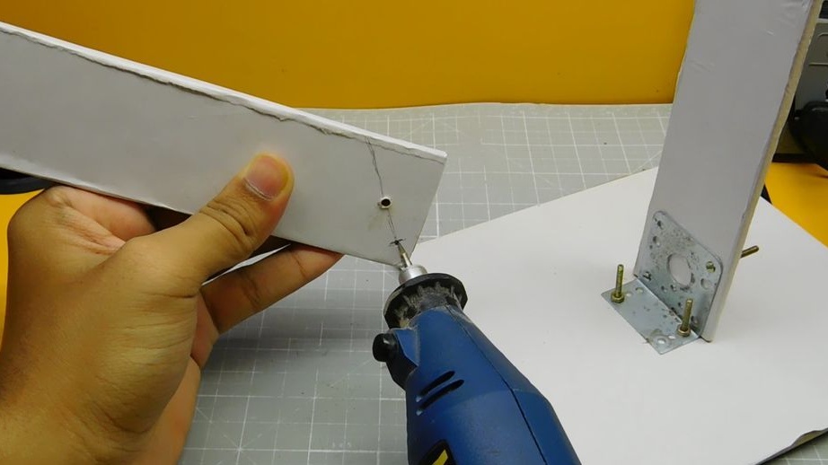
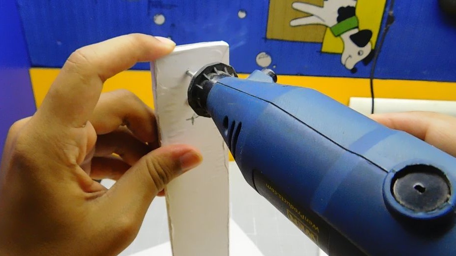
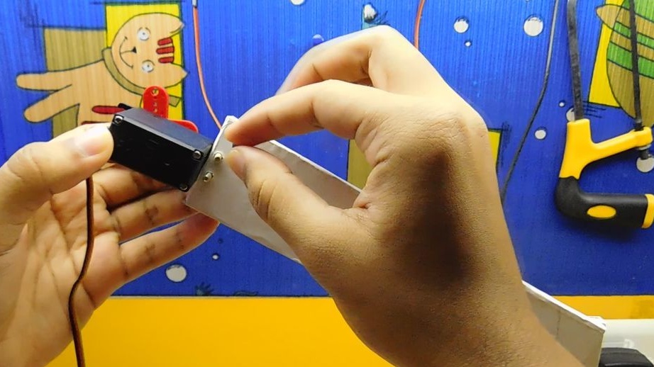
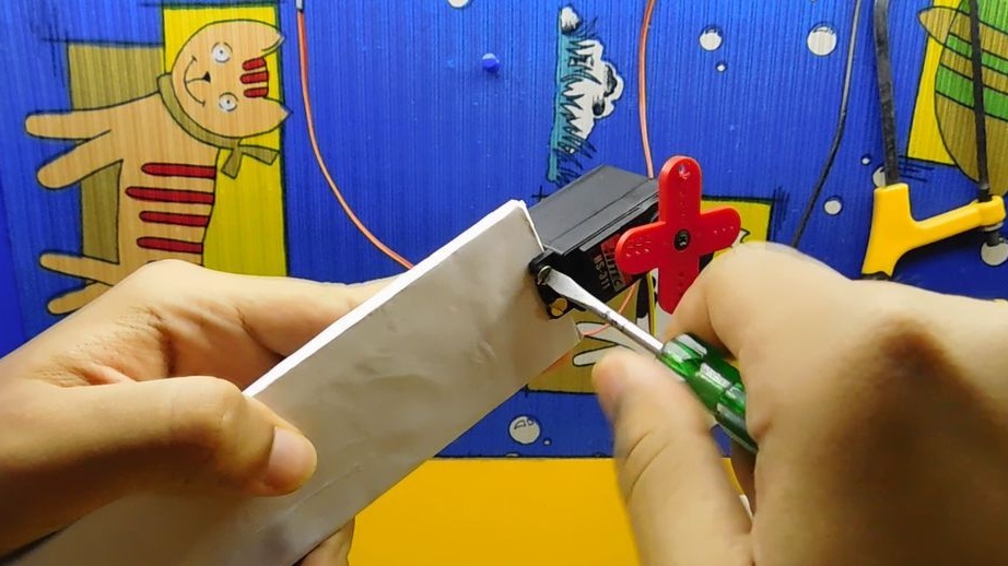
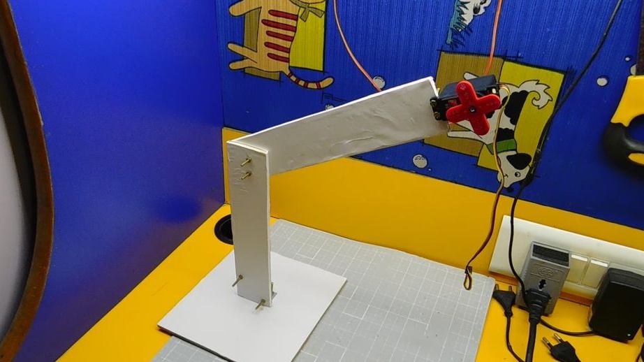
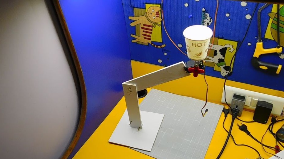
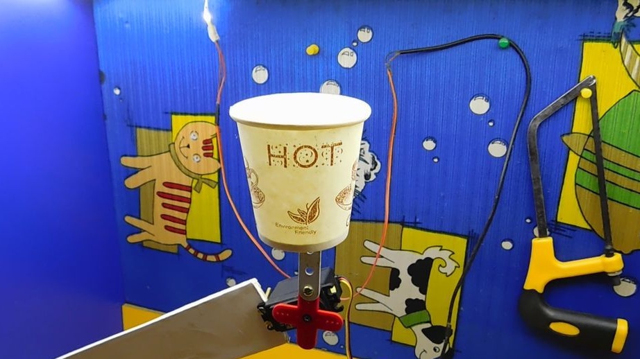
Step Nine: Stand
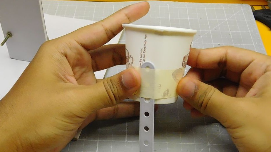
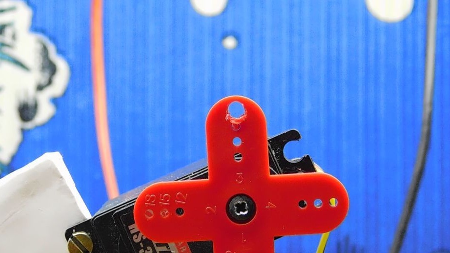
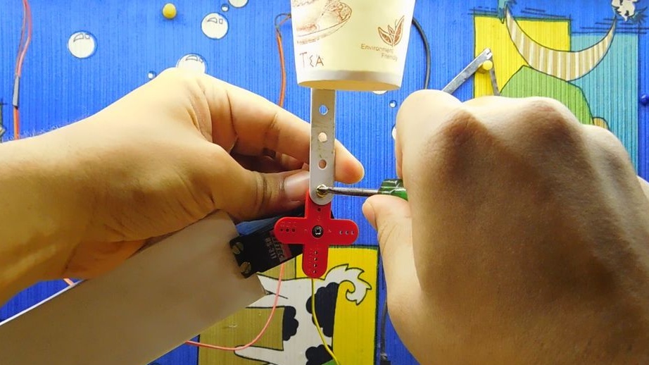
From plywood makes a rack. The base of the rack is 15 * 15 cm. Two levers 20 * 5 cm each. The upper lever is fixed at an angle of 45 degrees. A servo motor is attached at the end. A glass of water is fixed to the servomotor.
Step Ten: Download Code
For the new real-time clock module, you must first load the current time and date. To do this, download the libraries "DS1307RTC" and "Time". Goes to the arduino development environment and selects “include library”. Click "ZIP library" and select the downloaded ZIP files separately. Now the libraries will be imported.
Restarts the IDE. Opens a sample code named "SetTime" file> examples> DS1307RTC. Loads it to the arduino board. Goes to serial monitor. The time will be automatically loaded into the RTC chip and will be displayed on the monitor.
For the main code, another RTC library is used. Loads a zip file named “RTClib” and import it into the IDE, following the same process as above. Restarts the IDE.
Now loads the main project code. Links to the libraries below.
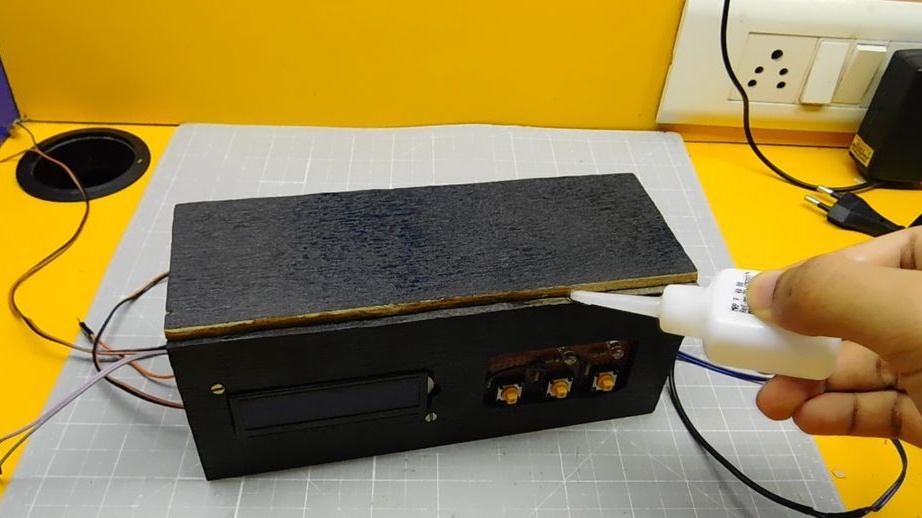
Step Eleven: Final Assembly
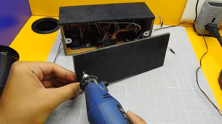
After downloading the code installs the rest of the panel body. The master glues the top cover.
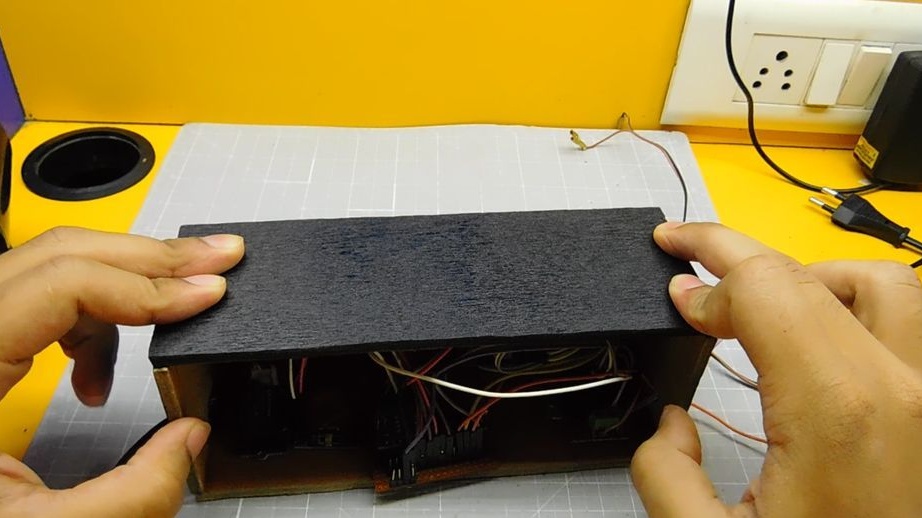
The back screws, leaving the possibility of access to the electronics.
Connects a servo motor.
Vcc ---- 5v
Gnd ---- gnd
Signal ---- D9
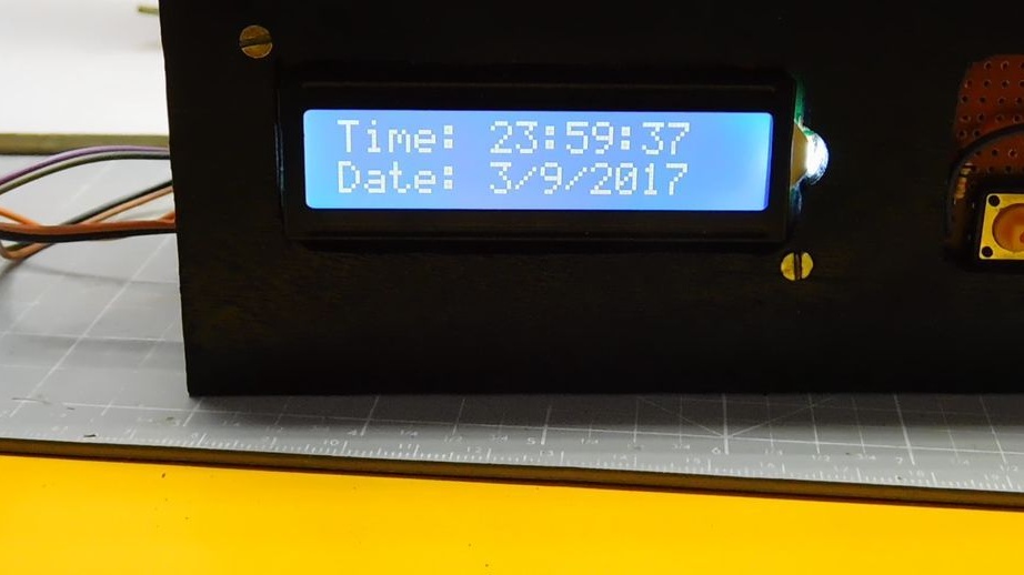
Connects the battery. Now the display should show the current time.
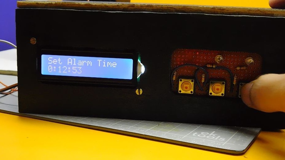
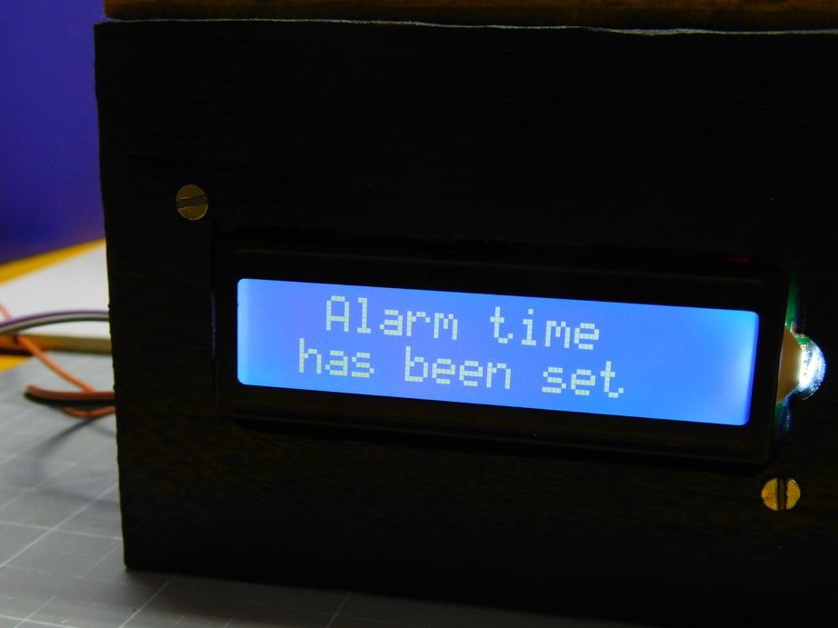
Step Twelve: Setting an Alarm
To set the alarm time, perform the following actions:
Presses button 1 - To increase hours, presses button 2 - To go to minutes, presses button 3 - To increase minutes, presses button 2 - Lock presses button 3.
An alarm clock for the most drowsy is ready. Good night and do not forget to pour in a glass of water.