
Hello. In this article, I will describe in detail to you and, perhaps, show you. How to make a mini laboratory power supply.
A power supply is what you need to have in every home, because you need it not only to charge the batteries, but also to test the performance of various electrical appliances. Much has been said about the manufacture of bulky and very powerful power supplies.
But often, even masters do not need a lot of power, not to mention lovers for home goals. We will collect an inexpensive and compact version.
For the manufacture of this laboratory power supply we need.
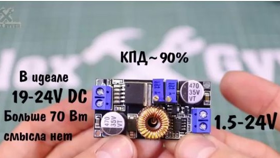
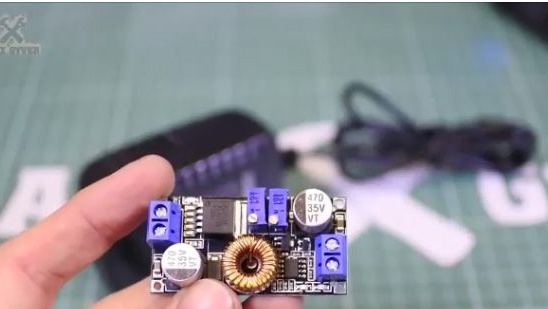
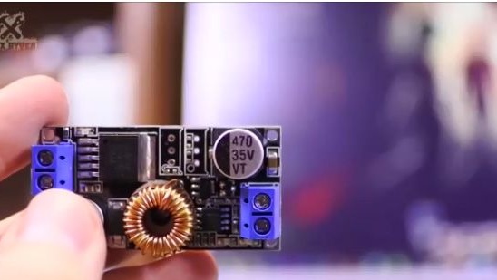
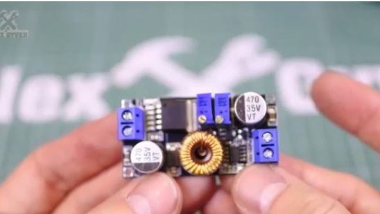
1- Step-down Chinese converter. Namely, the XL4015E1, which can be purchased from the Chinese at a relatively inexpensive cost, by going to the end of the article.
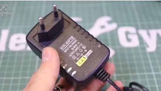
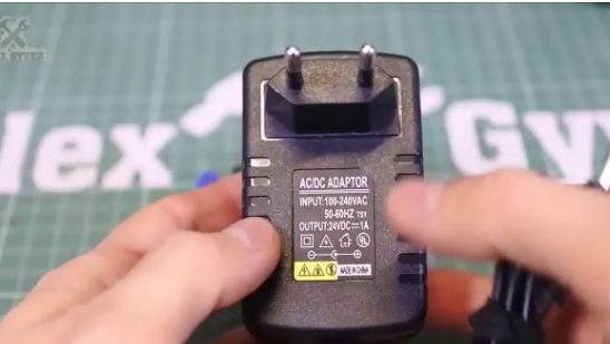
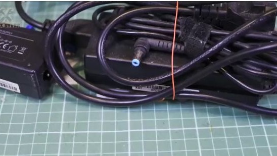
2- A power supply, for example, from a laptop, preferably at 24V and at least 1A DC. But we will use Chinese, which can also be purchased by going to the end of the article.
3- potentiometers 2pcs.
4- Glue thermal paste.
5- Voltammeter.
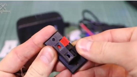
6- Nests for an exit. Keyless audio port.
7- Crocodiles.
8- The entrance to the entrance.
9- Switch.
10- Chinese corps.
11- Soldering iron.
12- Nippers.
13- Solder.
14- Screwdriver.
15- Self-tapping screws.
16- Mounting wire.
17- Term Shrinkage.
18- Drill or screwdriver
19- Drills.
20- Knife.
21- Ruler.
22- File.
23- Aluminum profile.

Making a homemade compact power supply
1- First, let's figure out what our laboratory power supply will be like. In general, the idea is this: the power supply in its separate factory building is installed in a power outlet and does not interfere with the table, it connects with a wire to our mini laboratory power supply, which is compactly on the table.
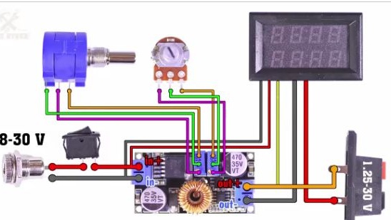
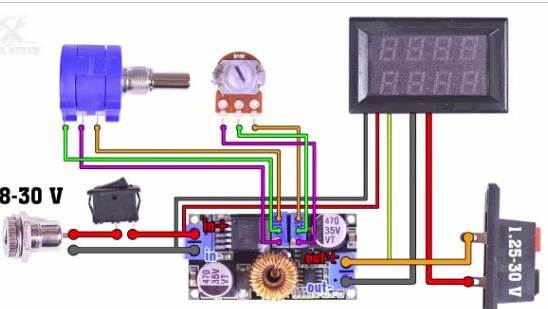
2- And we will connect all the components, we will use this scheme (see photo below).
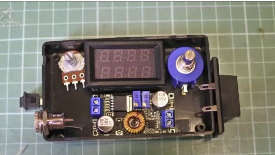
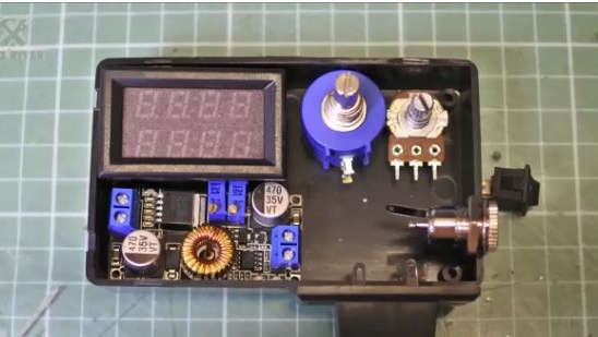
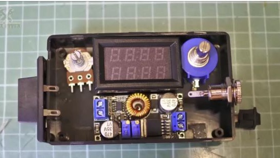
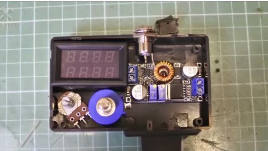
3- Now we will need to decide how we will arrange all the components in the case. This Chinese case is perfect for these purposes and it is possible to compactly arrange all the components in different layout options. Examples can be seen in the photos below.
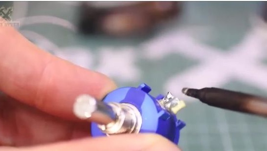
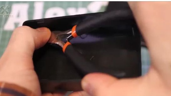
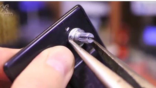
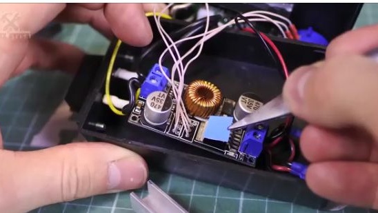
4- We will begin, perhaps, with the simplest, namely, with the extraction of standard potentiometers from the lowering board.
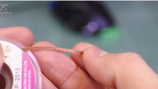
5- For soldering potentiometers, you can use a special braid for soldering or braid from an old TV cable.But we will act in the old fashion, we tilt the potentiometer with our finger and quickly warm up the soldering places until one side of the potentiometer comes out.
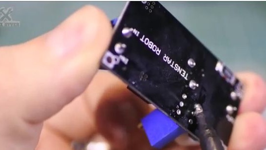
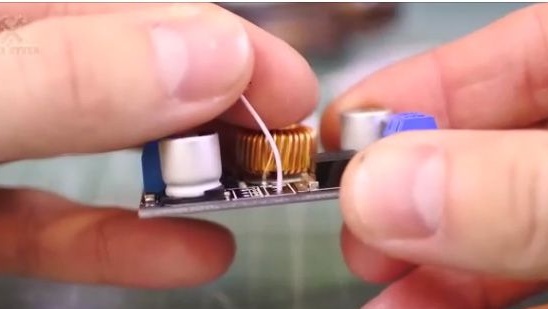
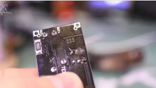
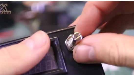
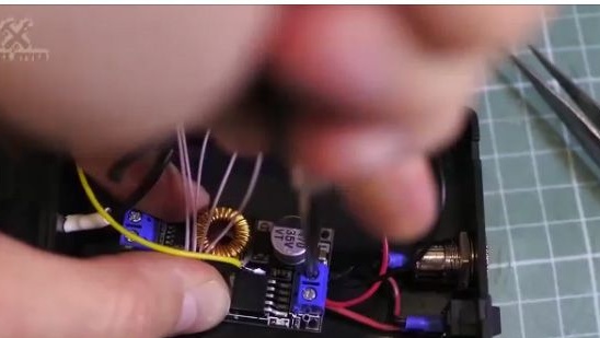
6- This is what the buck converter should look like after we dropped the standard potentiometers out of it.
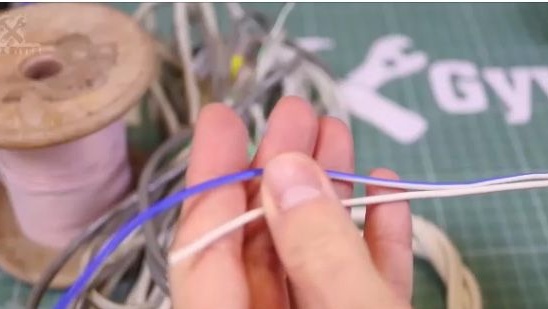
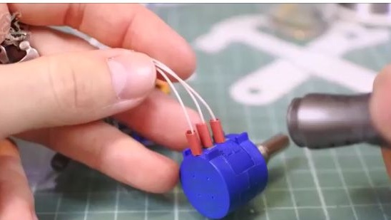
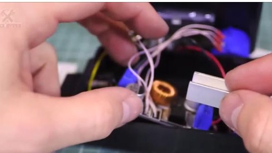
7- The diagram shows that there are thin wires and thick power wires. As thin wires we will use a simple installation wire from China, and as a power audio cable that can be obtained from the old speaker. Any cable with a cross section of at least 1 mm2 is suitable as a power cable.
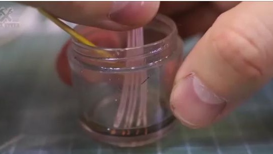
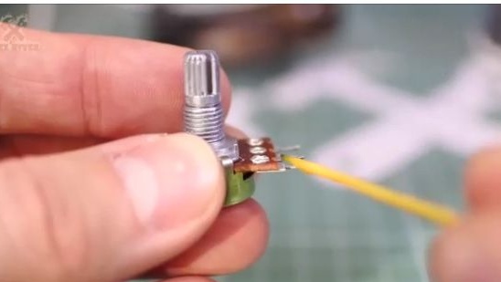
8- Well, let's solder the potentiometers. Remove insulation from thin pre-prepared wires.
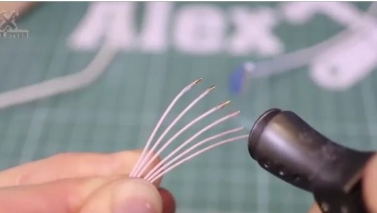
9- Fluxing.
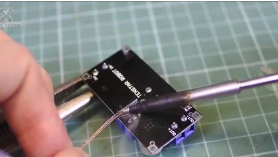
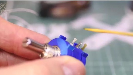
10- And solder the wires. We solder them to where the regular potentiometers have recently been pulled out.
11- Then we solder the wires just soldered to the new potentiometers. Solder should be according to the scheme. Do not forget to use heat shrink in the joints. It is also worth remembering that potentiometers can be very easily overheated.
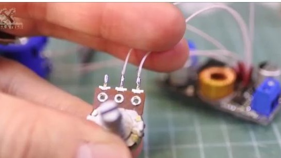
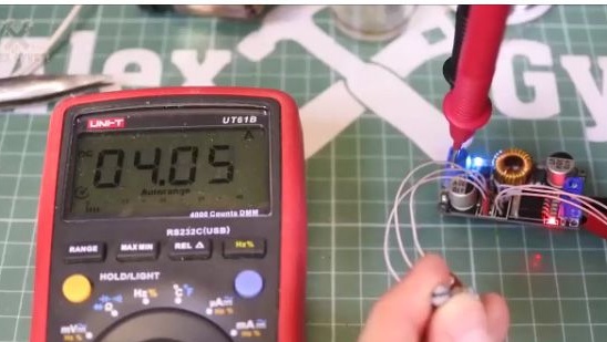
12- Using a multimeter, we check the efficiency of potentiometers.
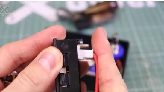
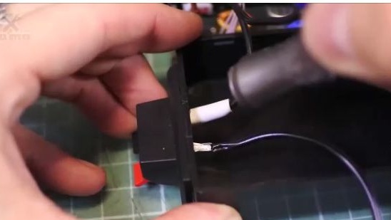
13- We turn to the multimeter. The multimeter itself fits perfectly into the case, but the plug of the power connector abuts against the bottom. This means that if you use the same case, you will have to do without a plug.
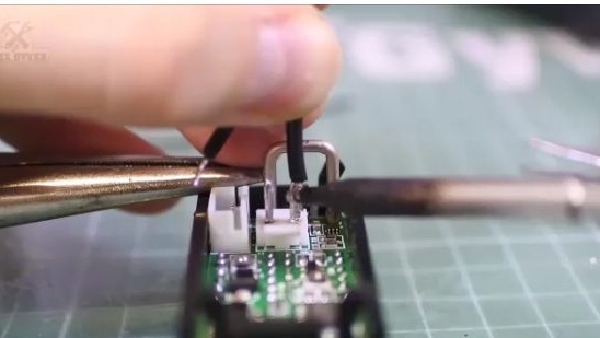
14- So we take and solder the power wires directly to the multimeter (see photo below).
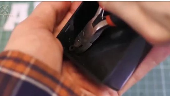
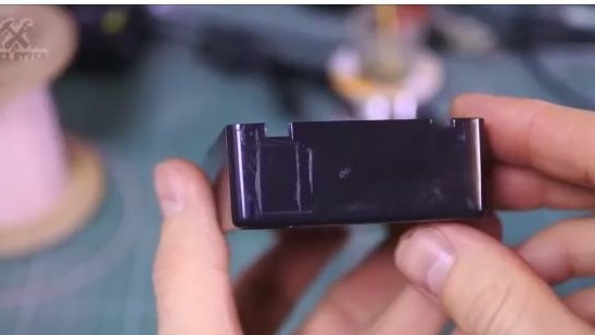
15- After which, using the cutters, bite the racks inside the case, otherwise they will simply interfere.
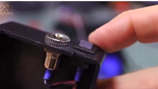
16- After which we will need to make holes in the housing for the potentiometers and for the multimeter.
We mark the seats on the case
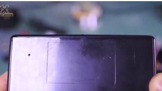
17- Similarly, place the windows under the other components.
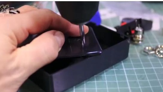
18- We drill the places for potentiometers using a drill.
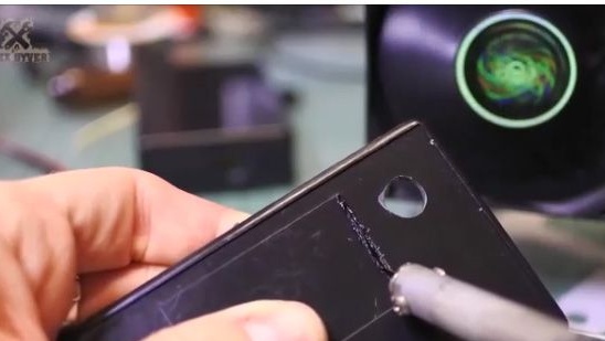
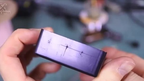
19- And we cut out the windows under the multimeter and the switch using a slightly heated soldering iron with a thin sting.

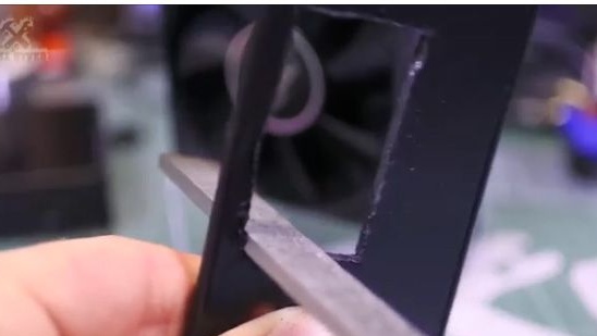
20- After which we process the edges of the windows just cut with a file or sandpaper.
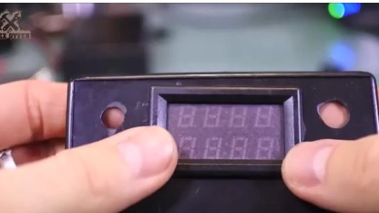
21- Insert the multimeter in its place.
22- We insert and fasten the potentiometers.
23- Then we solder the socket and the switch, not forgetting to use the term shrinkage.
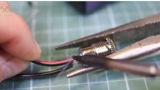
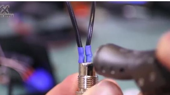
24- Insert the audio connector, then solder the wires to it according to the diagram, also do not forget to use thermal shrinkage.
25- Next, insert according to the wire diagram into the clamping terminals.
26- Do not forget to screw the output connector.
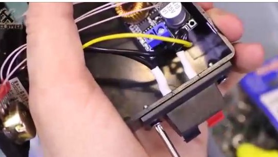
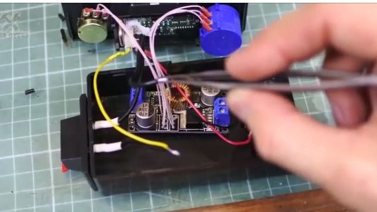
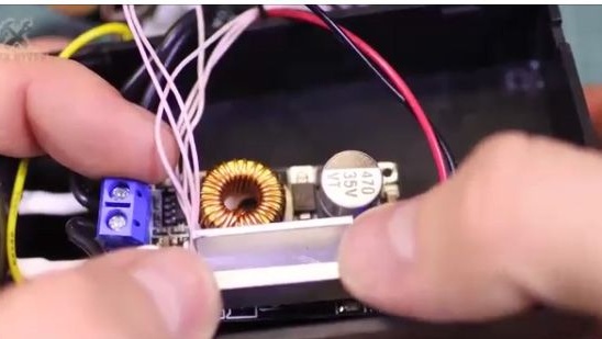
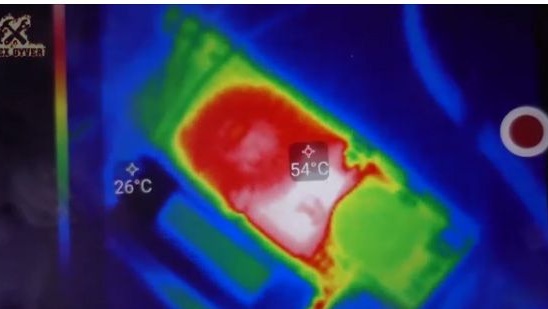
27- But before you finish you need to take care of cooling, since everyone knows that this Chinese module has the property of heating.
28- For cooling, we will use a “P” shaped profile from a hardware store.
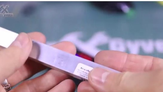
29- Cut a small piece. The piece should be sized so that it fits easily on the board.
30- We will attach the aluminum profile to the adhesive thermal paste or double thermal tape.
31- That's all, then just assemble the case, latching it.
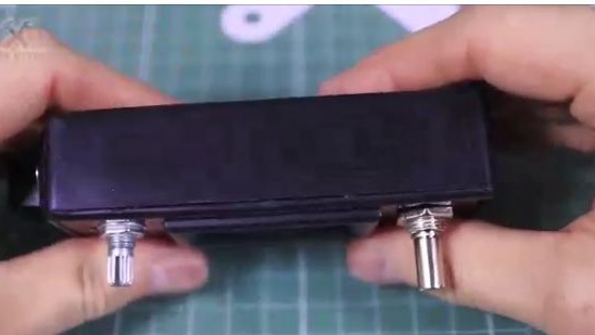
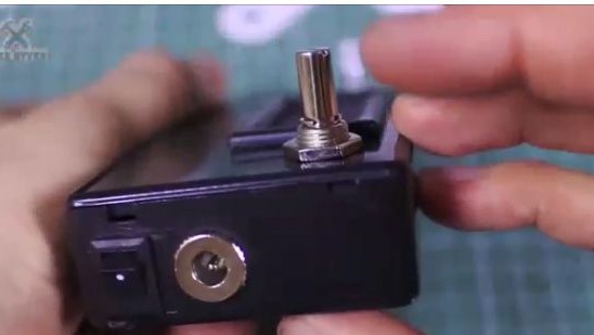
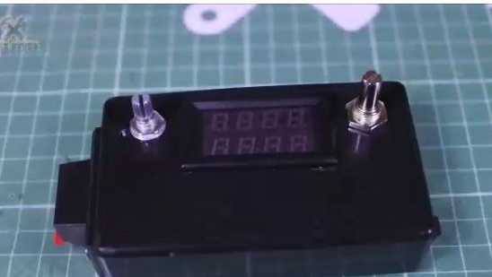
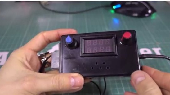
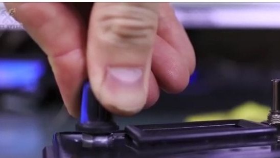
32- Insert the caps on the potentiometers.
33- And you're done!
Conclusion:
We got pretty aesthetic homemadefor which it would not be a shame.
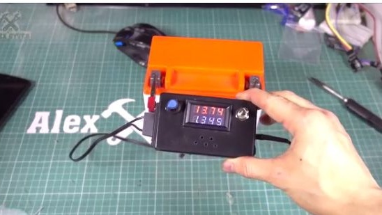
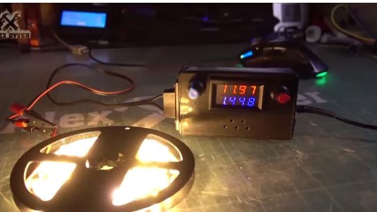
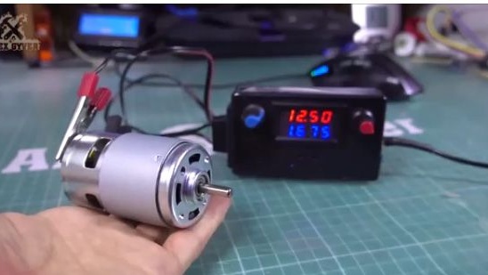
We check the performance of the power supply. And we see that it works.
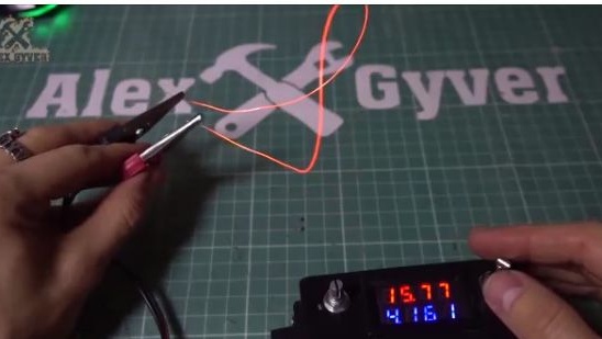
After conducting small tests, we learned that this power supply can produce 24V and 3A for a long time. But most likely you will not need such a lot of stress, especially for a long time. Now you have a practical and always needed customizable power supply, on which you can charge the batteries and use for laboratory purposes.
Also, some components for assembly can be ordered by clicking on the links below:
Thank you for your attention. I hope this article was useful for you, and also you have a wonderful opportunity to watch the video assembly of this homemade product and see more detailed instructions for charging the batteries using this laboratory power supply.