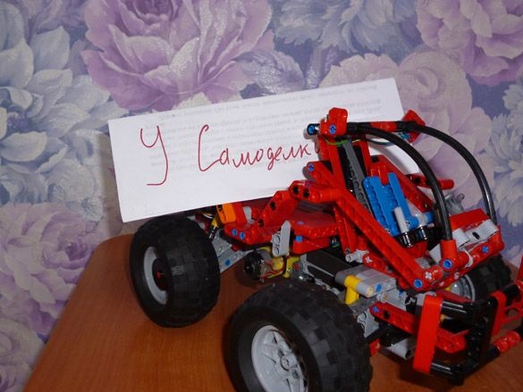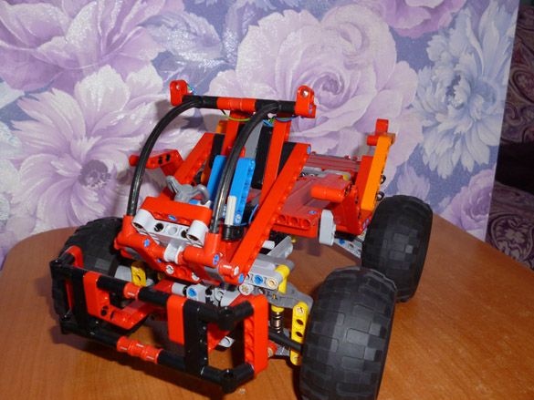
I'm still interested in the topic of combining Arduino and Lego Technic. And today I will share instructions for the manufacture of a four-wheeled vehicle. I called it the Mars rover for its unusual shape. The basis will be taken on the assembly instructions Lego Technic 42029, and then the flight of my imagination. For control, we will use the Bluetooth module associated with the android device or computer.
We will need:
- Lego Technic 42029
- Lego Technic 42033
- Arduino Pro Mini 5v AT Mega 328
- L9110S engine driver
- 1 servo drive SG-90
- Bluetooth module HC-05 or equivalent
- USB-UART for arduino firmware
- Motor gearbox 6v 1: 150 100 rpm
- 2 LEDs
- 2 resistors 150 ohms
- Capacitor 10v 1000uF
- 2 single row combs PLS-40
- Inductor 68mkGn
- 2 Li-ion 18650 batteries
- Connector dad-mom two pin to wire
- Homutik
- Wires of different colors
- solder
- Rosin
- soldering iron
- Bolts 3x20, nuts and washers for them
- Bolts 3x40
- Bolts 3x60
- Clerical or just a sharp knife
Step 1 Preparation of the mechanical part.
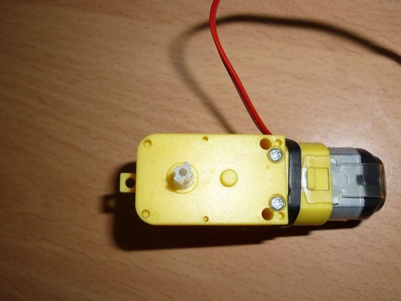
The 6v 1: 150 100 rpm gear motor is necessary for our model and drives the rear axle. You can experiment and try another gear ratio. 100 rpm in my opinion is optimal. The geared motor is not intended for connection to Lego parts. Therefore, it needs to be redone a little. A sharp or clerical knife must be shaped like a cross to the output shafts of the gearbox. The cross must be the same size as the regular Lego cross axis.
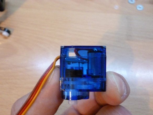
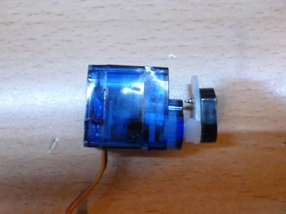
For the rotation of the wheels we will use the servo SG-90. It is also not intended to be connected to Lego parts. To fix it on our model, it is necessary to carefully drill, so as not to touch the internal parts of the servo, a through hole with a diameter of 3.2 mm or just cut it with a stationery knife. In this hole we will insert a bolt to connect with Lego. And also cut off the protruding parts (“wings” for fastening):
On the servo shaft we put on a lever with a screwed part from lego:
Step 2 Assembly
To assemble the case we need the instruction Lego 42029. It can easily be downloaded from the official website.
You must download both the first and second parts.
The base of the rear axle is assembled according to the instructions of Lego 42029 part 1, starting from 3 pages to 8 inclusive. Add a little to attach the springs:
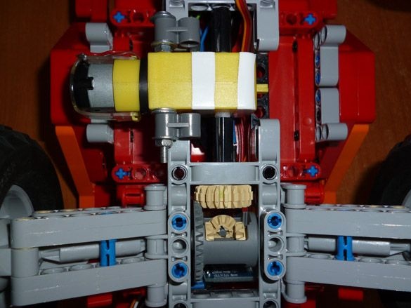
On the trimmed axis of the gearmotor we put on the Lego connecting sleeve. The gearbox itself is fastened with a 3x60 mm bolt as shown in the photo:
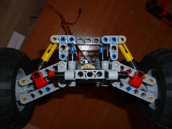
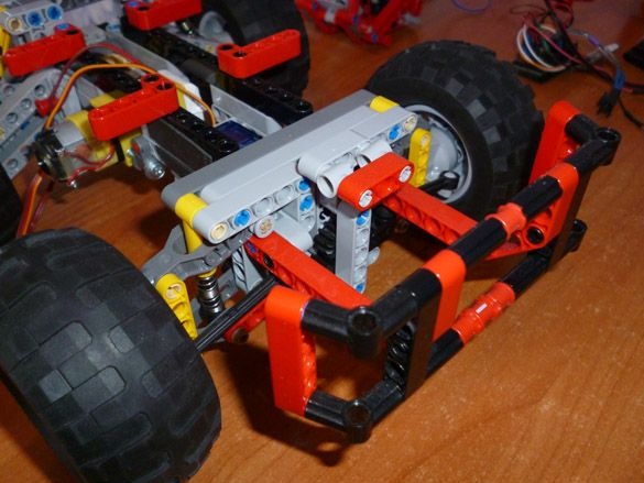
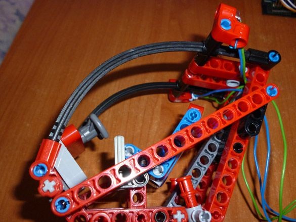
We pass to the front. We assemble the front part of the suspension according to the instructions of Lego 42029 part 1, from page 21 to 23. We take the trapezoid from the second part of Lego instructions from page 6 to 11. Add details in front as shown in the photo:
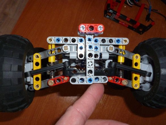
We build the front bumper as shown in the photo:
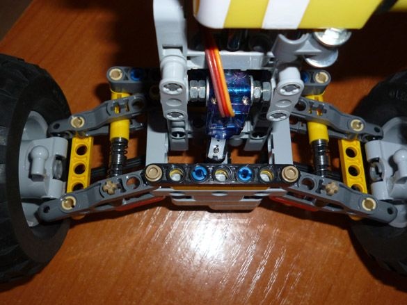
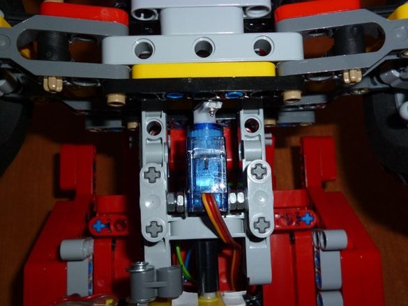
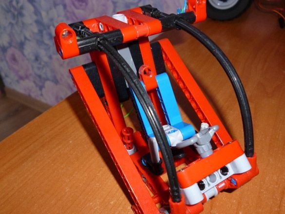
We fix the servo drive approximately in the middle of the machine, and connect it with a shaft with a gear turning the wheels:
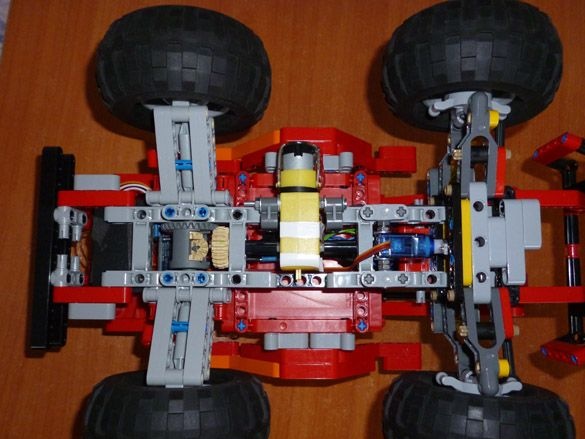
We connect both parts together. From below everything should look like this:
The cabin must be assembled from the photographs:
Add LEDs as headlights:
We put the cab on top of the front axle. We collect the bumper from the back and fix the plate:
It remains to assemble the middle platform, also from the photo:
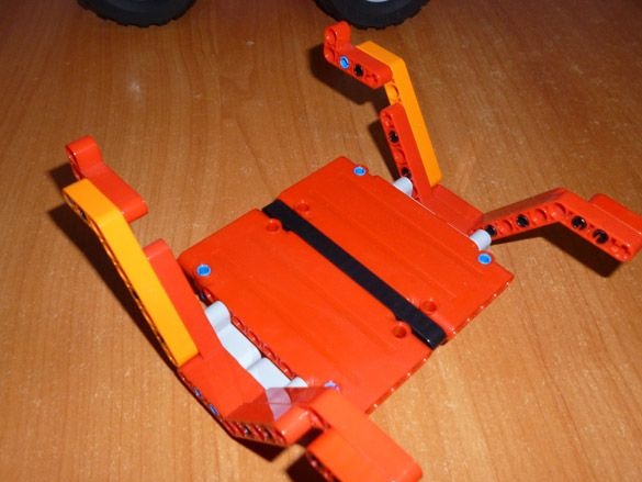
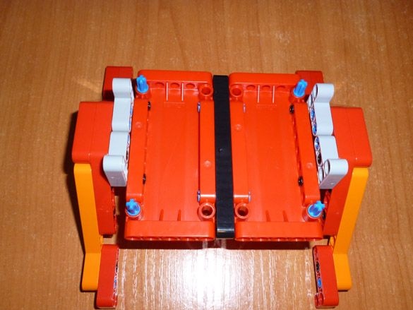
Put it in place:

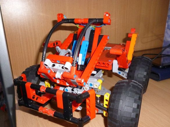
This completes the assembly of the case.
Step 3 Electrician.
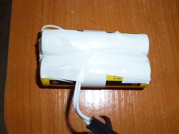
To power the motors and the Bluetooth module, we will use two Li-ion 18650 batteries soldered in parallel. Also, for ease of connection, it is worth soldering a connector to them:
For power Arduino is easiest to use a separate power supply, for example, 9 volt crown. If you don’t want to push the battery there, you can power the Arduino from the same batteries, but at the same time, insert a 68μH inductor into the gap of the positive Arduino power cable, and also connect a 10v 1000uF capacitor to the same power line. Connect the control wire of the servo to pin 2, and the motor driver to pin 5 and 6:
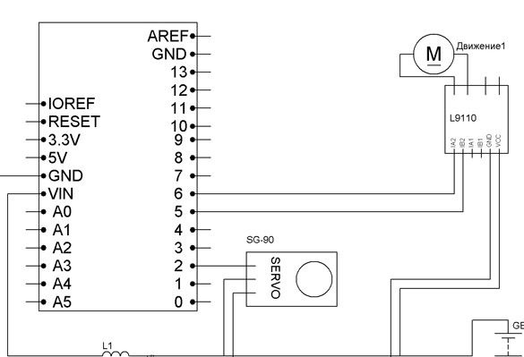
You can also connect the headlights. To do this, we connect through the resistors the anodes of two LEDs to 4 pin Arduino, the cathodes to GND. Resistors are selected for the LEDs used.
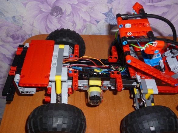
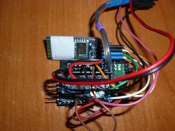
All the assembled electrics do not take up much space:
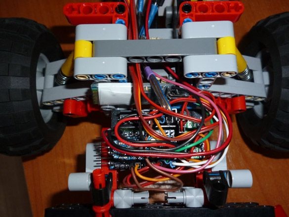
We place it in the back of the "rover", under a large plate:
Step 4 Preparing the programming environment.
We will use the Arduino IDE to write the sketch. Version should be no lower than 1.8. Download from the official site.
Next, add the libraries to the Arduino IDE. This project uses two libraries Servo.h (for controlling a servo drive) and SoftwareSerial.h (for communicating with a Bluetooth module):
You need to download and install them. You can do this by unpacking the archives and moving all the files to the “libraries” folder located in the folder with the Arduino IDE installed. Or you can use another way - without unpacking the downloaded archives, select the Sketch - Connect Library menu in the Arduino IDE. At the top of the drop-down list, select the "Add .Zip Library" item. And indicate the location of the downloaded archives. After installing the libraries, be sure to restart the Arduino IDE.
Step 5 Configure the Bluetooth module.
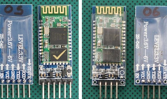
The most common Bluetooth modules to date are the HC-05 and HC-06. They are abundant in both Chinese online stores and among Russian importers. HC-05 can work both in master mode and in slave mode. HC-06 is a slave device only. In other words, HC-06 cannot detect a paired device and establish communication with it, it can only be a slave.
As a rule, modules are sold as two boards soldered together. The smaller one is a factory module, widely used in various electronic devices. Large - a special breadboard for DIY projects. It looks like a smaller board with a BC417 chip:
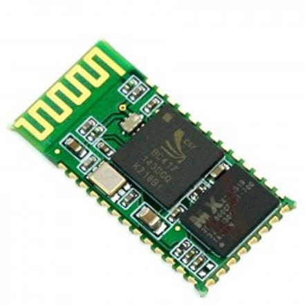
And so the DIY modules HC-05 and HC-06 themselves:
You can use any module you like. A module without a breadboard costs less, but then you will have to take care of the 3.3 V power supply for the module and torment yourself by soldering wires to the module. I chose the optimal, in my opinion, in the price / functional ratio HC-05. Each time with firmware, disconnecting the Bluetooth module from the Arduino, in my opinion, is inconvenient, so we will use the software port for communication. This is possible thanks to the SoftwareSerial library.
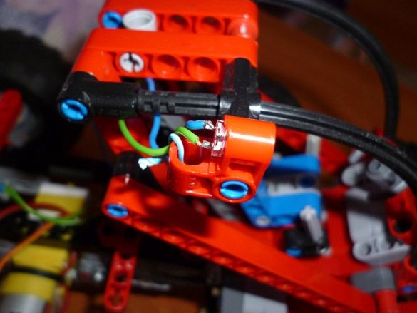
We connect as follows:
Arduino Pro Mini - Bluetooth
D7 - RX
D8 - TX
5V - VCC
GND –GND
For proper operation, the module must be configured. Setup is done by entering AT commands in the terminal window. I will configure the HC-05 module. If you have a different setting may be different. To connect the computer and the Bluetooth module, you need to fill in the next sketch in Arduino. At the same time, Arduino will act as a link between the Bluetooth module and the computer:
After filling in the sketch, open the terminal window, set the speed to 9600, and enter the following commands:
“AT” (without quotes) the answer “OK” should come (it means everything is connected correctly and the module is working)
“AT + BAUD96000” (without the quotes) the answer “OK9600” should come.
If you have the right answer, go to the next step.
Step 5 Fill the sketch in Arduino.
The next step is to download and upload the following sketch to Arduino:
Step 6 Set up your phone.
For an Android phone, we need to install the robot control program via Bluetooth. There are many, differ in appearance and functionality. You need to enter “Bluetooth Arduino” in Google play and select the one you like. I recommend BT Controller. It is free, and there is enough functionality to control our machine. Download and install on any Android device. Next, through the settings of the Android device, you need to establish a connection with our module. The password for the connection is “1234” or “0000”. Then configure the program for the appropriate commands. The list is below.
Step 7 Configure Windows (if necessary)
For those who like to use a desktop computer, laptop or windows device, there is a program that allows you to send commands via Bluetooth channel. To do this, this device must have Bluetooth. We establish communication with our module through the device management tools. The password for connecting is the same “1234” or “0000”. You can use the terminal to send commands. Any convenient for you. Having written the firmware, control is carried out by the following buttons (by teams):
W - forward
S - back
A - left
D - right
F - stop
G - steering wheel
K - headlights
L - headlight off
Using the terminal for control is not very convenient. Therefore, I recommend Z-Controller. In the program, you need to select the port (com port through which the connection occurs) and configure the keys for the appropriate commands. Set up idle and intuitive. I post the program itself and the settings for our "rover":