

In the modern world, automation has penetrated literally into all areas of human life. We all sometimes want soulless automation to do some boring routine for us — water the flowers, ventilate the room, feed the cat, give the dog a drink ... It's not easy to say that laziness is the engine of progress, because a lazy person is ready to work hard and create such electronic a device that will do for him everything that is required. And if a lazy person is friends with a soldering iron, then the matter remains small, only create this very automation.
In this article, we will consider the process of creating an electronic timer that will turn the load on and off at the specified time. Such a timer can be found in many applications - for example, once a day with it to water flowers, or beds in the garden. Automatically turn on the light at night and turn it off during the day when it is light, or pour water into the drinker once a day. In general, the device is absolutely universal, the scope is not limited to anything.
Scheme:
The diagram has two control buttons, numbered with the numbers "1" and "2". Button "1" sets the time to turn on the load, and button "2", respectively, the time to turn off. To better understand the principle of operation, consider this example: there is a Christmas tree garland that must be turned on at 13:00 every day and turned off at 15:00. So, to set the time intervals for the timer, you need to press the “1” button at 13:00, while the relay turns on for about a minute, then wait 15:00 and press the “2” button, the relay again turns on for about a minute, signaling about successful time setting. In the future, the relay will automatically turn on the garland at 13:00 and turn off at 15:00 every day. A flashing LED indicates that the device is working.
The circuit contains two microcircuits - the Attiny13 microcontroller and the DS1307 clock microcircuit. The supply voltage of the entire circuit is 12 volts. Thanks to the 78l05 linear stabilizer, on the circuit board the microcircuit receives the power they need 5 volts, and the relay winding is powered by 12 volts.In parallel with the relay coil, a low-power diode should be installed, for example, 1N4148. The SS8050 transistor, the control relay, can be replaced with any other low-power NPN transistor. The buttons in the harness of the microcontroller should be taken without fixing.
The peculiarity of the DS1307 clock microcircuit is that it can work from a backup power supply, if the main thing disappears. To do this, to its conclusions 3 and 4, you need to connect a 3 volt power source, for example, a CR2032 battery. In this case, in the event of a power failure, the countdown will continue, as soon as the main power appears again, the device will continue to work in the previous mode, turning the relay on and off at the set hours. Do not forget to put electrolytic and ceramic capacitors in parallel with the power supply of both the main and the backup capacitors, in order to suppress interference of any kind. The LED resistor coming from the 7th leg of the clock microcircuit can be reduced to 0.5 - 1 kOhm, then its brightness will noticeably increase.
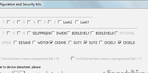
Before installing the microcontroller on the board, it must be flashed, the firmware files are attached to the article. This is most conveniently done using a USBASP programmer. When using a new, previously unused microcontroller, the fuses should not be changed. From the factory, Attiny13 microcontrollers are clocked from an internal generator with a frequency of 9.6 MHz, an 8 divider is on.
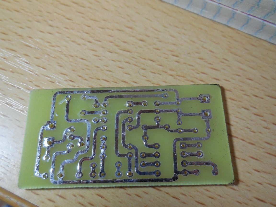
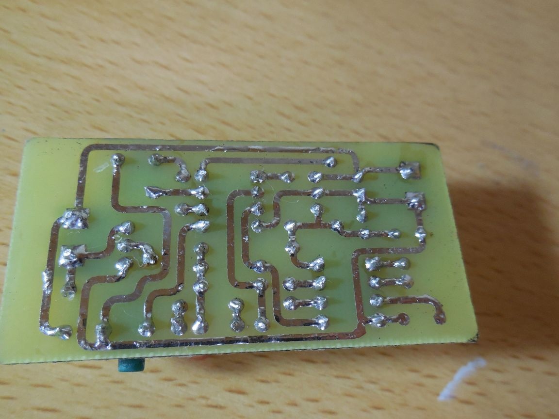
The printed circuit board can be made using laser-ironing technology, the so-called "LUT". Photo of my board:
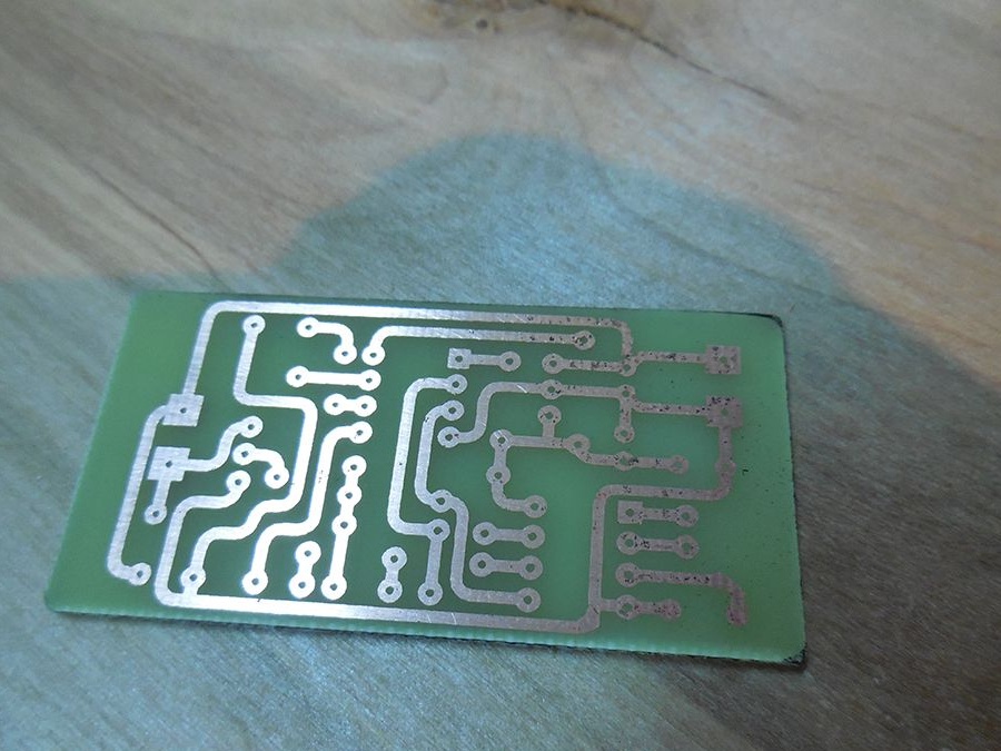
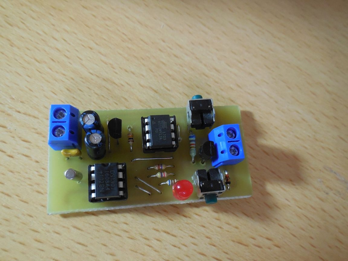
After tinning, the board takes the following form:
List of required parts:
0.125 W Resistors:
• 6.8 kOhm (682) - 1 pc.
• 10 kOhm (103) - 1 pc.
• 4.7 kOhm (472) - 2 pcs.
• 3 kOhm (302) - 1 pc.
Capacitors:
• 100 microfarads (electrolytic) - 2 pcs.
• 100 nF (ceramic) - 2 pcs.
Rest:
• Attiny13 microcontroller (+ socket) - 1 pc.
• Chip DS3107 (+ socket) - 1 pc.
• Transistor SS8050 - 1 pc.
• Diode 1N4148 - 1 pc.
• Button without fixing - 2 pcs.
• The stabilizer 78l05 - 1 pc.
• 3 volt LED - 1 pc.
• Quartz 32768 Hz - 1 pc.
• Relay for 12 volts - 1 pc.
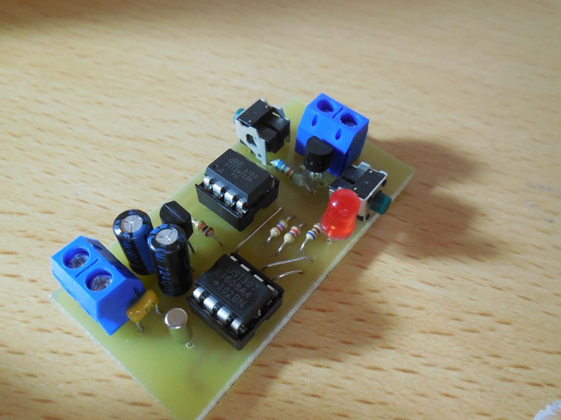
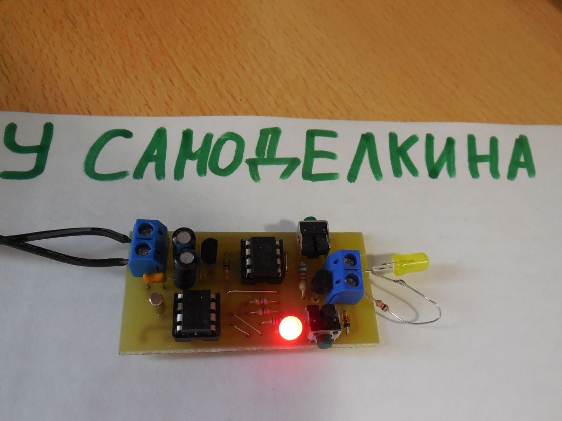
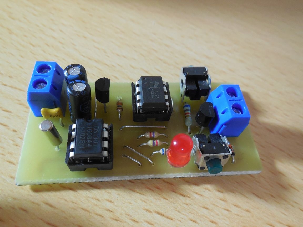
Photo of the device I collected:

The circuit, circuit board and files for the firmware are in the archive: