» Electronics »Universal PWM controller

Universal PWM controller


In amateur radio practice, it is often necessary to regulate the power of a device. Be it a drilling machine, LED strip, an ordinary light bulb or some kind of heater. You can use a linear adjustable stabilizer, but it requires a decent heatsink under heavy load. And it’s not rational to spend precious energy in heat. Recently, the so-called PWM controllers, which also allow you to adjust the power, but without the release of external thermal energy, have gained particular popularity. The abbreviation PWM stands for Pulse Width Modulation. The principle of operation of such a regulator is clearly shown in the figure:

Universal PWM controller


At the same time, the frequency of the PWM signal lies in the range of 20-40 kHz, which is outside the range of human hearing, so the regulator works silently. A variable resistor allows you to change the duty cycle of the pulses, thereby regulating the voltage supplied to the load.
The schematic diagram is presented below:


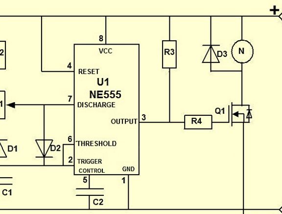
The ratings on it are as follows:
• R2 - 1 kOhm
• R3 - 1 kOhm
• R4 - 100 Ohms
• C1 - 2.7 nF
• C2 - 1 nF
• D3 - 1n4007
• D1 - 1n4148
• D2 - 1n4148
• R1 - 50 kOhm (variable resistor)
• Q1 - IRFZ44N

The supply voltage of the circuit is 12 volts, so it is convenient to use it in the automotive electrical network.
The key link in the circuit is the NE555 microcircuit, which forms rectangular pulses. It controls the field effect transistor Q1, which in turn controls the load. Any field effect transistor can be used here, for example, IRFZ44N, IRF740, IRF730, IRF630 or similar, suitable for current. Diodes are also any low-power, the values ​​of resistors and capacitors can deviate widely. The frequency of the PWM controller depends primarily on the capacitor C1, an increase in its capacity will lead to a decrease in frequency. If it falls within the range of a person’s ears, the circuit will start to make an unpleasant whistle. For the stability of the circuit, it is better to use film capacitors, it is enough to take resistors with a power of 0.125 watts. The field effect transistor in this circuit should not be heated, because it is either in a fully open state or in a closed state.If its heating occurs, it means that it is not opened, then you should check the circuit for correct assembly.

The adjustment in this scheme is minus, i.e. plus power circuits and plus power loads are connected, and minus are connected to different terminals on the board. Have a nice build!

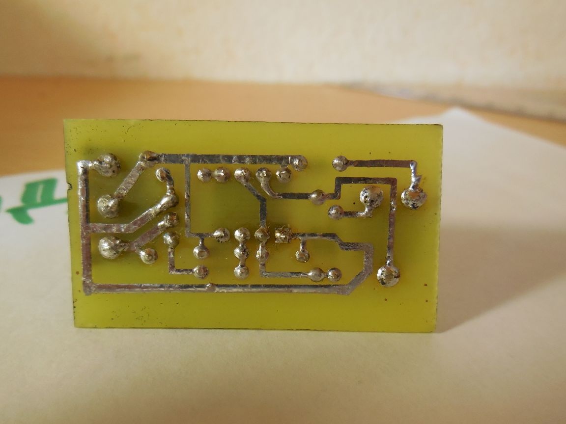
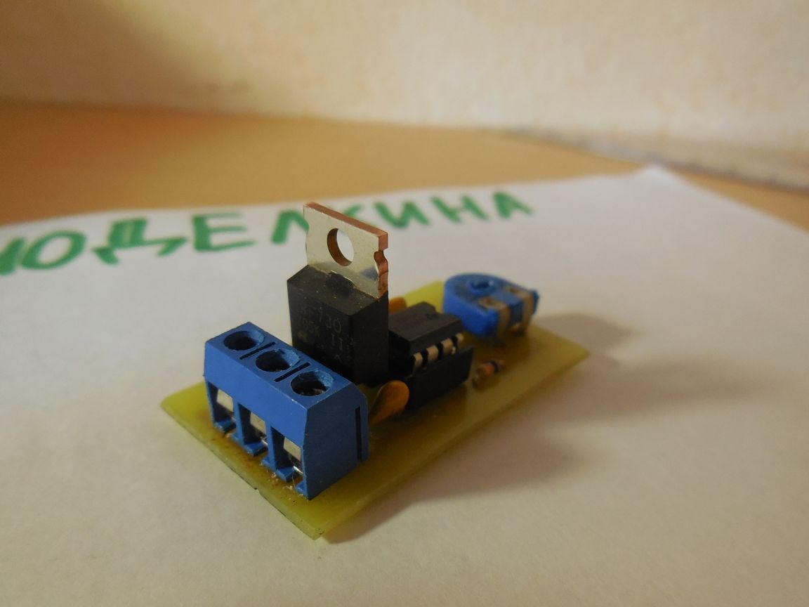
The circuit board is in this archive: pechatnaya-plata.zip [4.09 Kb] (downloads: 533)

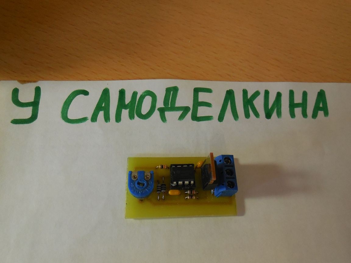
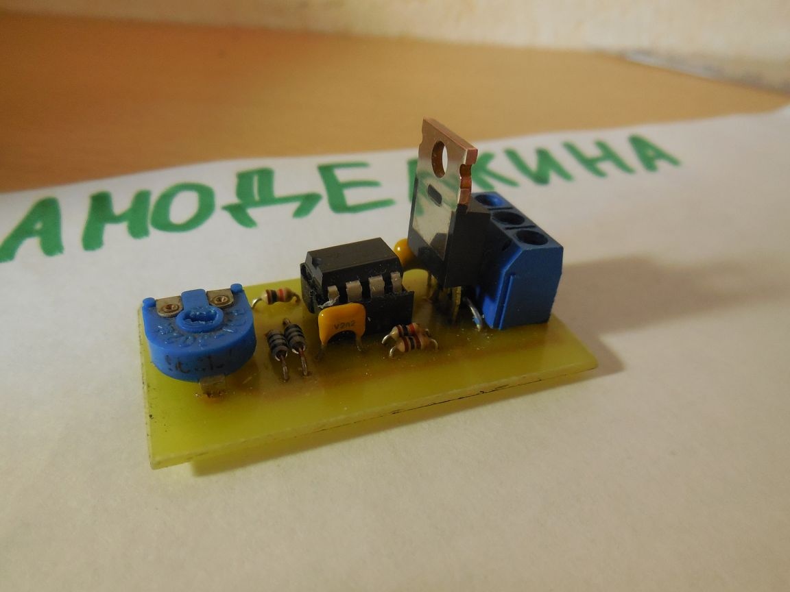
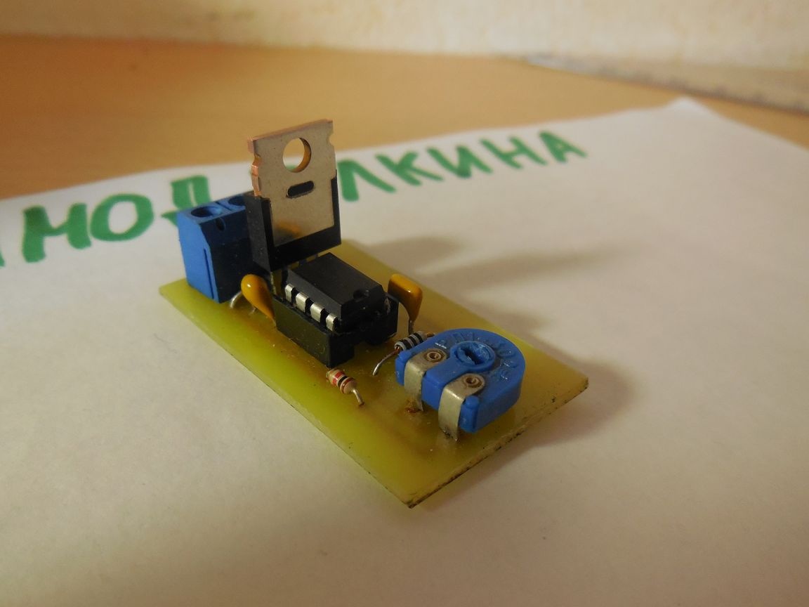
Photo of the controller I collected:


9.5
9.5
9.5

Add a comment

    • smilesmilesxaxaokdontknowyahoonea
      bossscratchfoolyesyes-yesaggressivesecret
      sorrydancedance2dance3pardonhelpdrinks
      stopfriendsgoodgoodgoodwhistleswoontongue
      smokeclappingcraydeclarederisivedon-t_mentiondownload
      heatirefullaugh1mdameetingmoskingnegative
      not_ipopcornpunishreadscarescaressearch
      tauntthank_youthisto_clueumnikacuteagree
      badbeeeblack_eyeblum3blushboastboredom
      censoredpleasantrysecret2threatenvictoryyusun_bespectacled
      shokrespektlolprevedwelcomekrutoyya_za
      ya_dobryihelperne_huliganne_othodifludbanclose
7 comments
The armature whistles, oscillating in a magnetic field by the generated PWM current of the relator. see pic filling in.
Valerymaybe in the clutch (torque limiter)?
Yes, and I’m very interested in what exactly this whistle can emit ... It’s not the engine that’s accurate and not the mechanics - if you press very carefully while holding the cartridge, it is at the moment of switching on that the cartridge does not rotate itself (and, especially, I hold it!), the whistle immediately appears. At the same time, it comes from the area of ​​the PWM controller (I did not check it with the disassembled case, but there is nothing more ...).
The other day I will find a burnt "hair" from him (I changed it somehow). I’ll take a picture of it, lay it out ... Together we’ll “ponder” that it might whistle ....
The mechanics are whistling, the engine itself. A throttle, for example, can also whistle, but in the screwdriver adjuster it most likely is not. In an electronic circuit that does not contain winding elements, there is simply nothing to whistle.
I don’t know why, but syst, zarrza !!! ))))
At me "Enhel" screwdrivers whistle ... If you very slowly press the "trigger", then a quiet whistle comes first. (The sound, rather, is similar to "the operation of a jet passenger plane when it rolls up take-off, or is it worth it if you listen to it from the TV"))))
Then, with the addition of speed, it is simply drowned out by the noise of the motor and gear)
If it falls within the range of a person’s ears, the circuit will start to make an unpleasant whistle.
What will the whistle scheme be?
The field effect transistor in this circuit should not be heated, because it is either in a fully open state or in a closed state.

This statement is true if the PWM controller is active. When working on an inductive load, the transistor does not work purely in key mode. An integrating chain is obtained here and the voltage has a sawtooth shape. The transistor, in any case, will warm up.

We advise you to read:

Hand it for the smartphone ...