

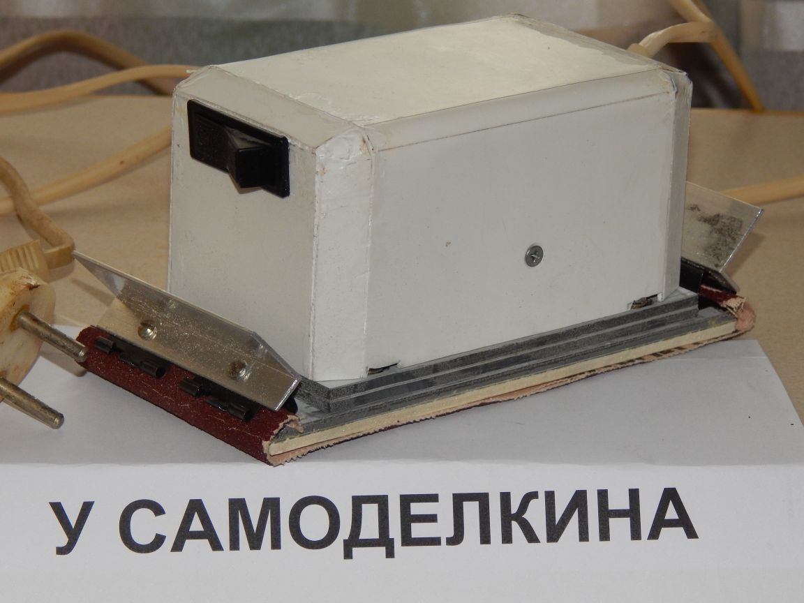
Hello everyone! I want to bring to your attention a vibration-type grinding machine, the basis of which was an old-style magnetic starter. It was conceived for a long time, I wanted to try out the principle of operation, and even if the first pancake was lumpy and the result did not quite live up to expectations, the machine turned out to be quite efficient.
I’ll make a reservation right away — the machine’s power is small, it is rather weak for rough processing, but it is suitable for processing putties and polishes, where strong pressure is not needed.
The weight of the machine was 0.7 kg, the current consumption was 1A (power 200W), the stroke was 3mm.
For the manufacture you will need the following materials:
1. Magnetic starter with a coil for 220V (it is possible for 110V, but you have to put a quenching resistor.
2. Textolite 3mm thick., Or something like that.
3. Aluminum corner 40x40mm. and 10x20mm.
4. Stationery clips 25 mm wide.
5. Porous rubber or expanded polystyrene 3 mm thick.
6. Screws, nuts M3.
7. Rectifier diode (I have IN4004 1A, 400V).
8. Key switch or button.
9. Shrink
10. Brass tube 5mm.
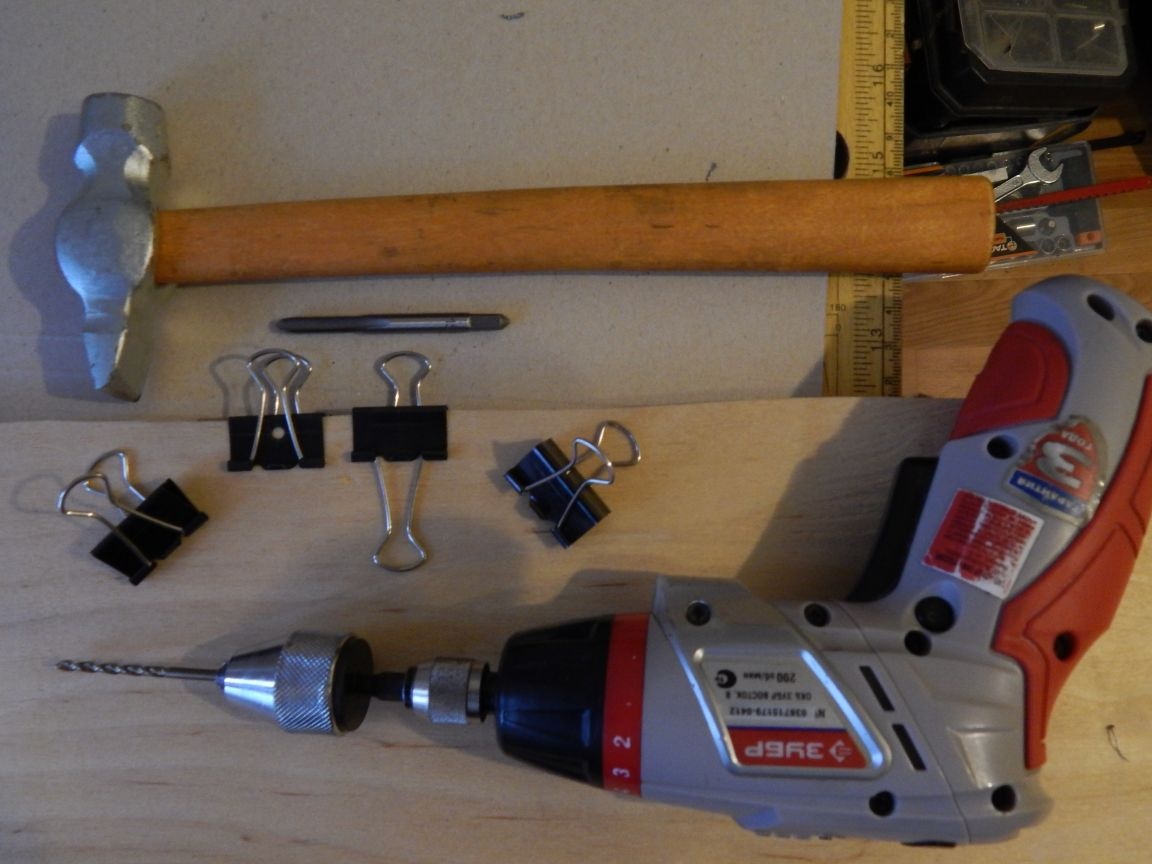
Tool:
1. Drill
2. Hacksaw
3. Drills on 2.5, 3.2, 2.1 and 4mm.
4. M3 taps
5. Vise
6. The hammer
7. Files and files
8. Soldering iron
9. Small pipe cutter
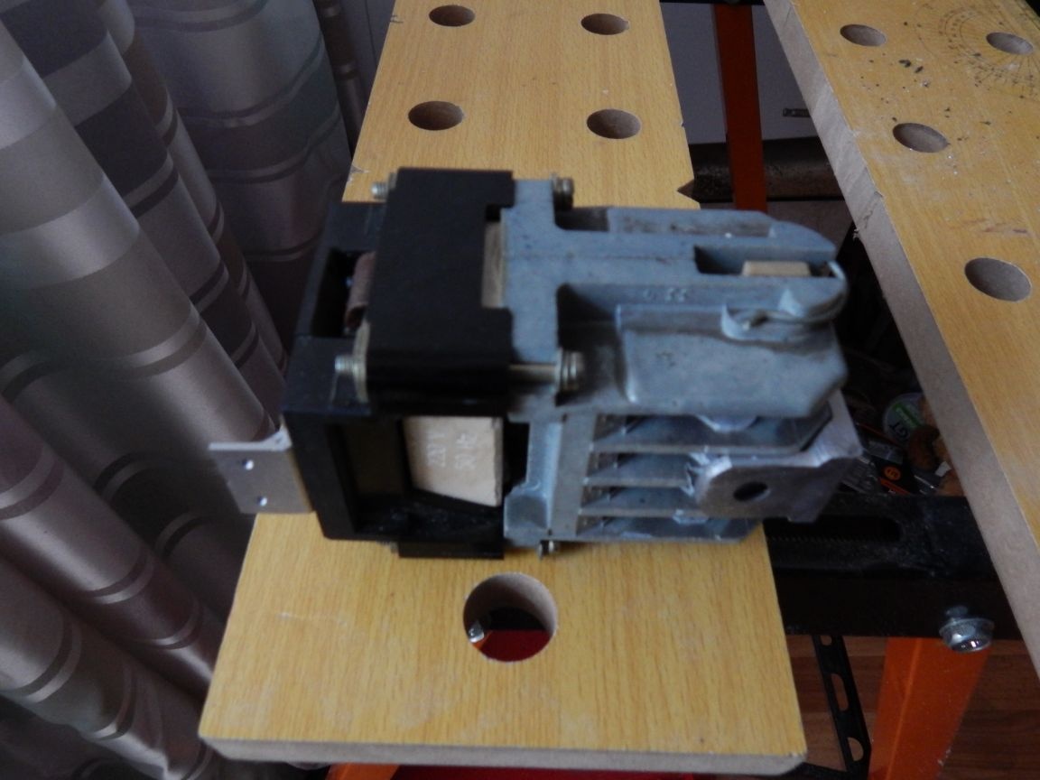
To begin, we disassemble the starter
On component parts
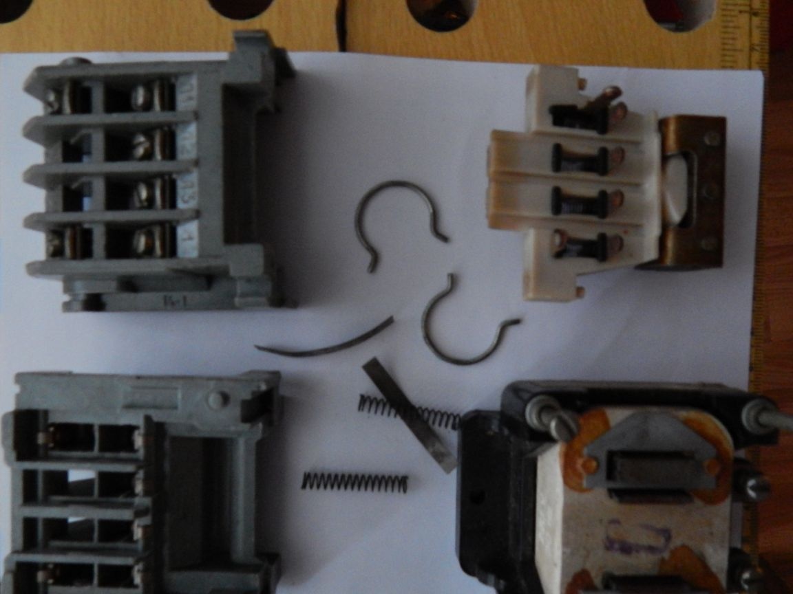
And modify it a bit:
We take out all the contacts
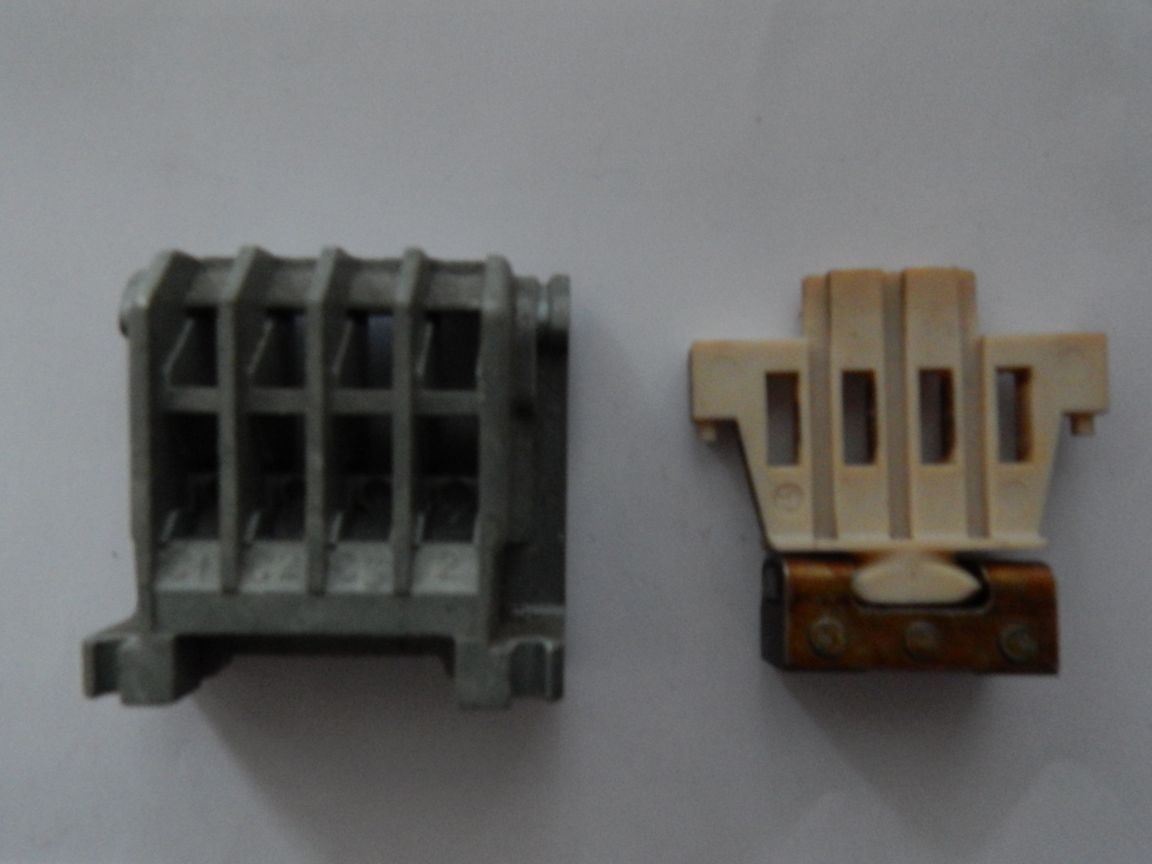
We expand the windows where there were contacts cutting out extra jumpers
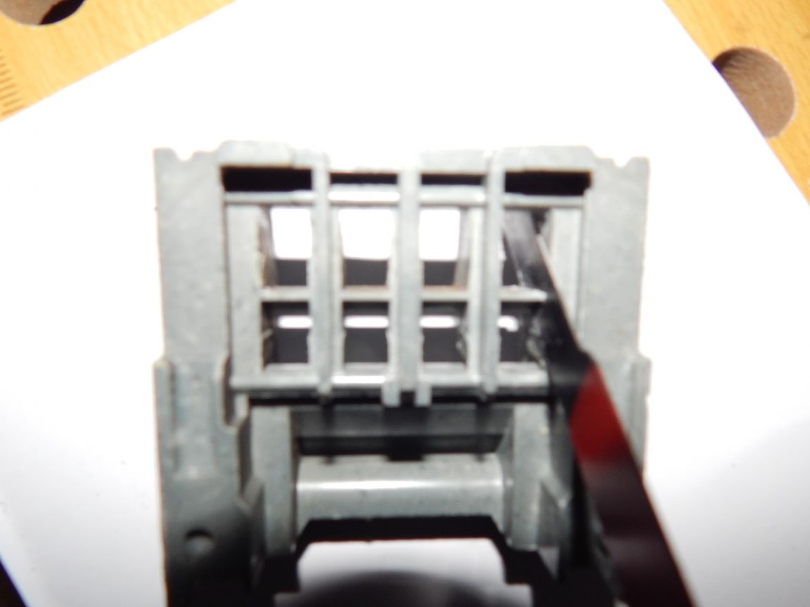
The result should be this
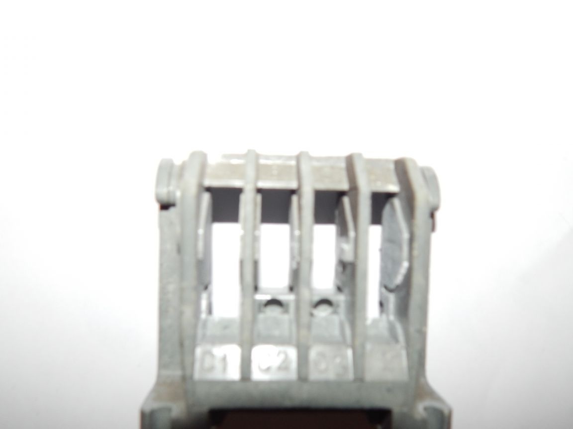
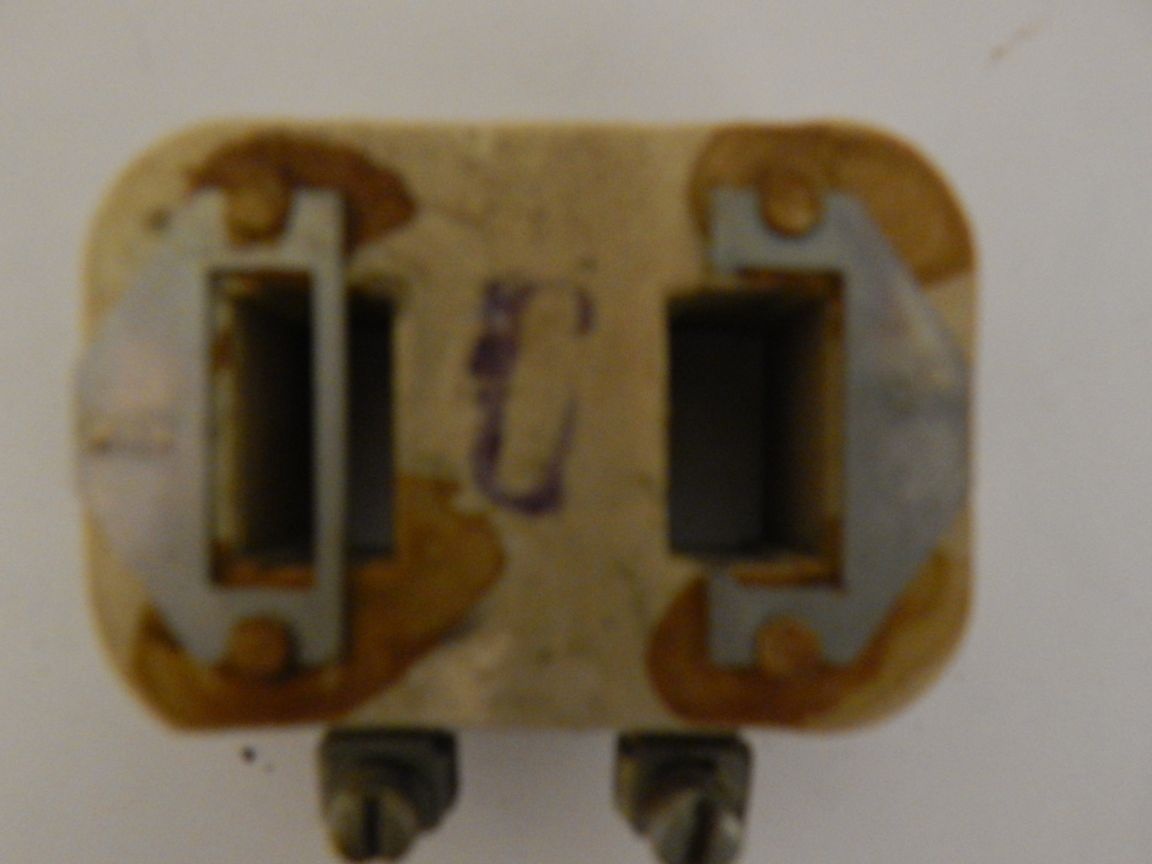
We remove the short-circuited coils of the magnetic circuit (the right jumper is removed in the photo), they will no longer be needed.
From the base we saw off the ears of the fastener as unnecessary and to reduce the overall dimensions.
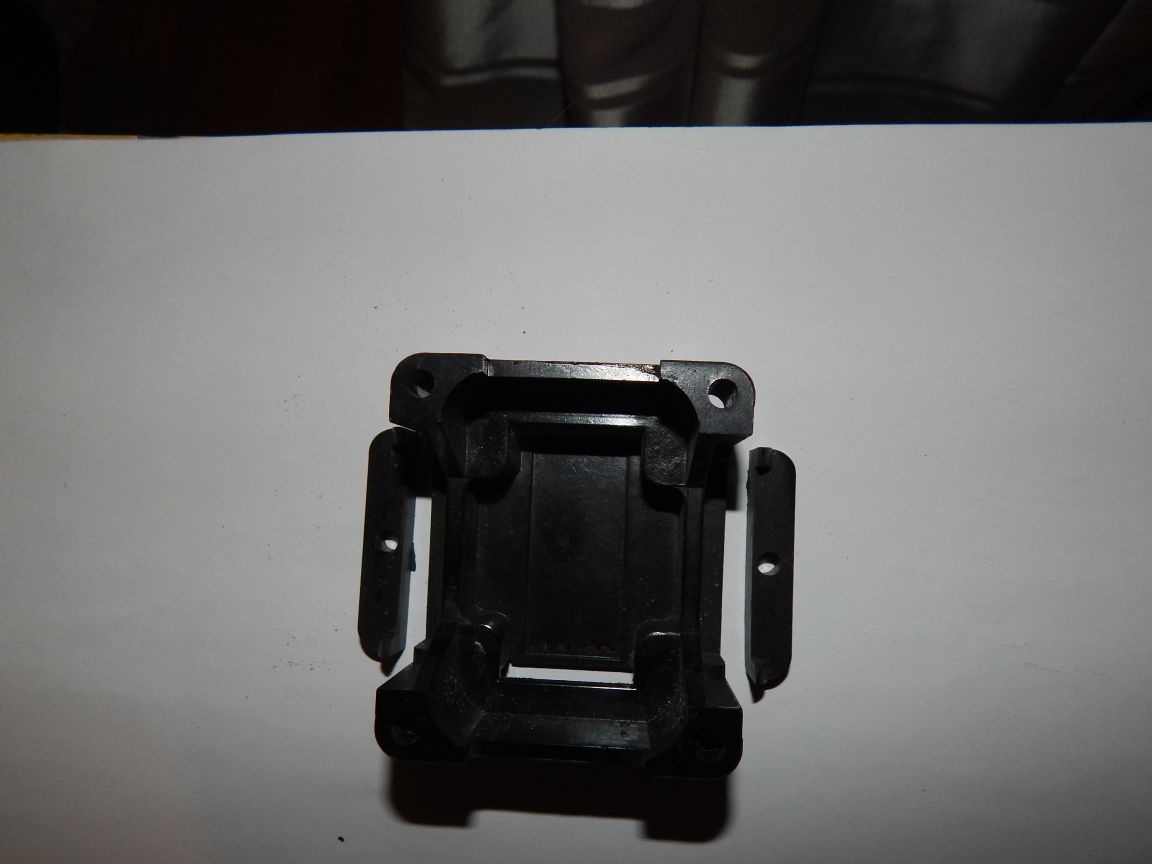
The starter will be mounted horizontally. We install mounting angles by cutting the threads in the starter housing and the corners in the shelves of attachment to the platform.
Next, proceed to the manufacture of the drive:
From the corner 40x40, saw off two pieces of 55mm.
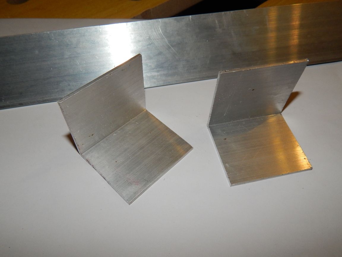
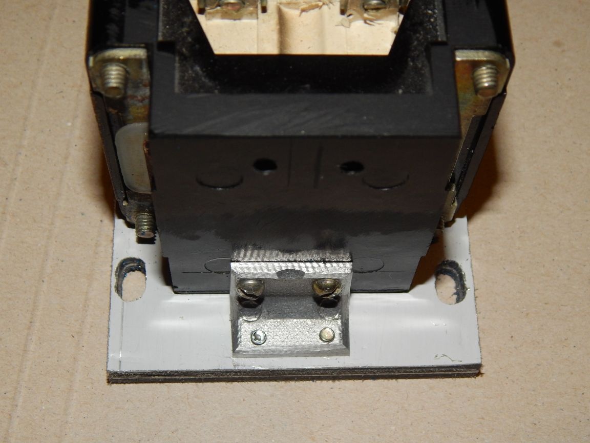
From the obtained blanks, we cut out the right and left brackets, one part of which should go into the window of the moving part of the starter, and the other should be attached to the sole of the grinder. In general, they will transmit the forward movement of the anchor through the sole of sandpaper.
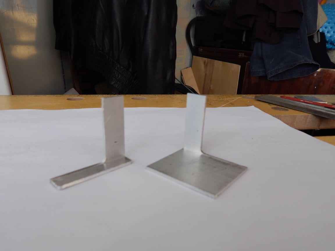
To strengthen the brackets and increase their thickness to the dimensions of the starter window, rivet the cut out corner piece and grind it to the desired size. This starter has a window width of 5mm. , the thickness of the corner is 2mm.so that in total two thicknesses give 4mm. which is enough for a dense installation of brackets.
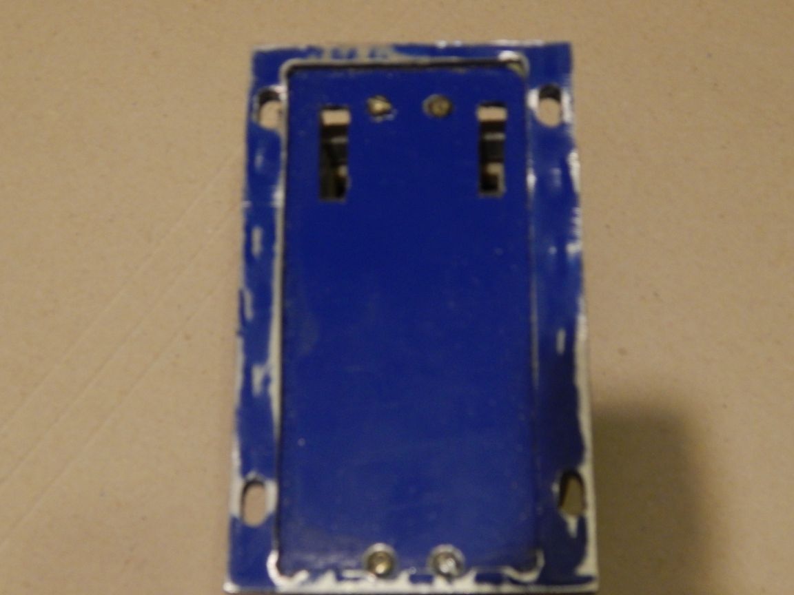
I wanted to make a platform and a sole from PCB because of its antifriction properties, but it was not at hand. And it turned out to be the so-called composite plastic on both sides glued with aluminum, but it will do. We cut two blanks for the platform and one for the sole. The sole is made across the width of the platform, and 30 mm longer for the working stroke and fasteners of the sandpaper.
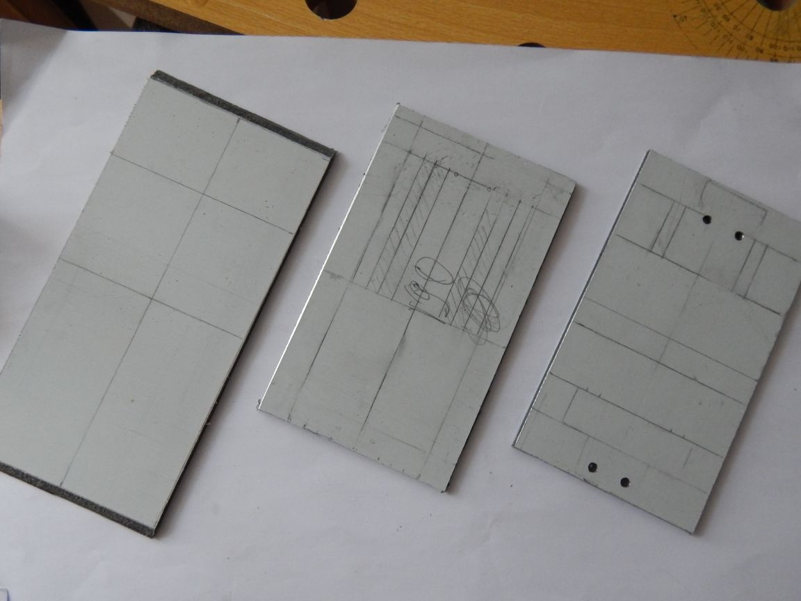
The platform can conditionally be divided into two parts — the base itself and the so-called “basement”, in which the sole brackets should move freely. At the base we cut the windows for the brackets and drill holes for the starter mounting, in the “basement” we simply cut out the opening, leaving 10 mm on each side and 5 mm on the front and back.
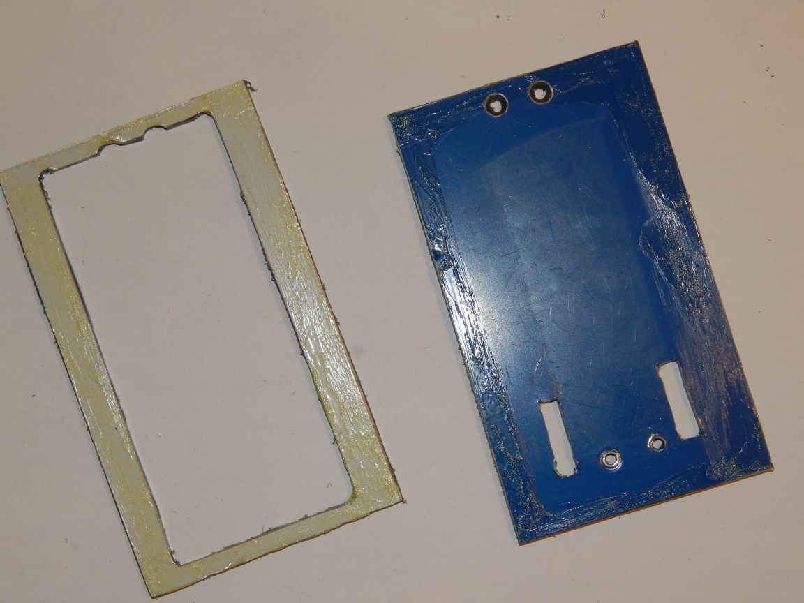
We glue the received parts among themselves with the Universal Moment glue. The edges are smeared with glue.
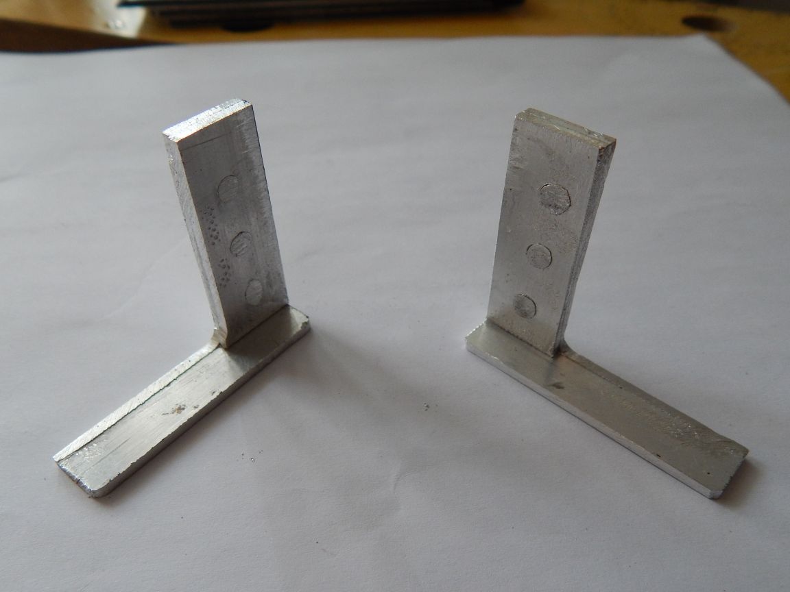
For fastening to the sole in the brackets, we drill holes for rivets with a diameter of 2.1 mm. By the way, more about rivets, I made them from aluminum wire 4-square with a diameter of 2.1 mm. (I don’t know if it corresponds to the state standard specification by section, but such a diameter).
We fasten the brackets to the sole. A drill of a larger diameter countersink holes for rivets, insert the wire into the holes of the parts to be joined, cut the wire with oversize of 1.5-2 mm with a pair of pliers, and then rivet it. Why did I choose this mounting method? The riveted connection is non-separable, and since strong vibration is assumed in my unit, this is the best solution. Moreover, the rivet gets flush with the part, and the space in the "basement" is limited to three millimeters (I recall the thickness of the bracket is 2 mm.).
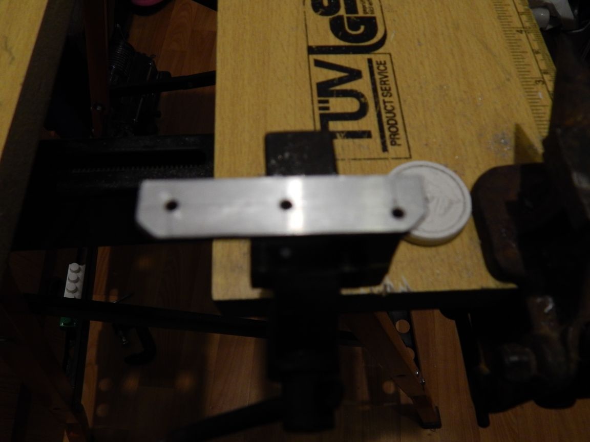
For the movable connection of the platform and the sole from a brass tube with a diameter of 5 mm. 4 distance bushings 6.5 mm long are cut with a pipe cutter.
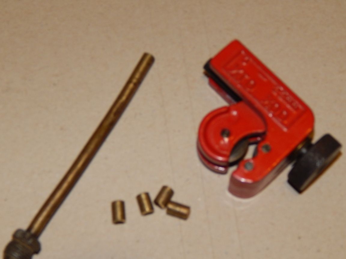
We mark and drill holes with a diameter of 3.2 mm in the sole and platform. In the platform, we drill holes in the two extreme positions of the sole's working stroke, then we use a file to connect them into one window. When processing the window we achieve a size at which 5mm. the tube moves freely from one edge of the hole to the other, without jamming.
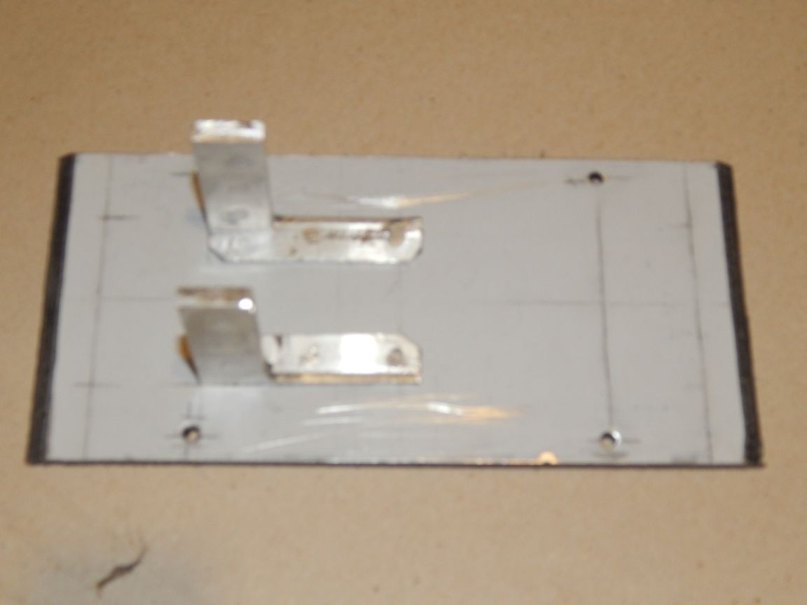
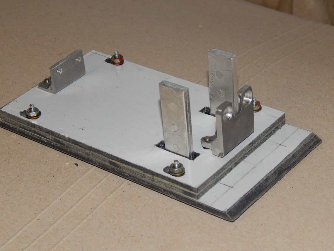
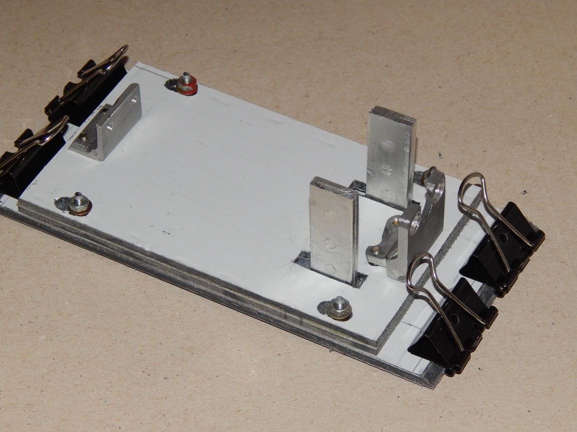
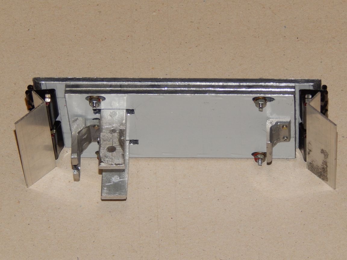
Assembled platform and sole look like this:
To fix the sandpaper on the sole, I used stationery clips 25 mm wide. Initially, I wanted to make a mount that allows you to quickly replace sandpaper, but I must admit this design is not the best option, some teeth will need to be attached, but for now it has grown, it has grown. So, 3.2mm holes were drilled in the clamps, (fears that the strong metal did not materialize - I simply patched it with a simple drill)
Then fasten the clamps with screws and nuts to the sole.
To simultaneously open the clamps, we fasten a 10x20mm corner to them. also a set of screws and nuts.
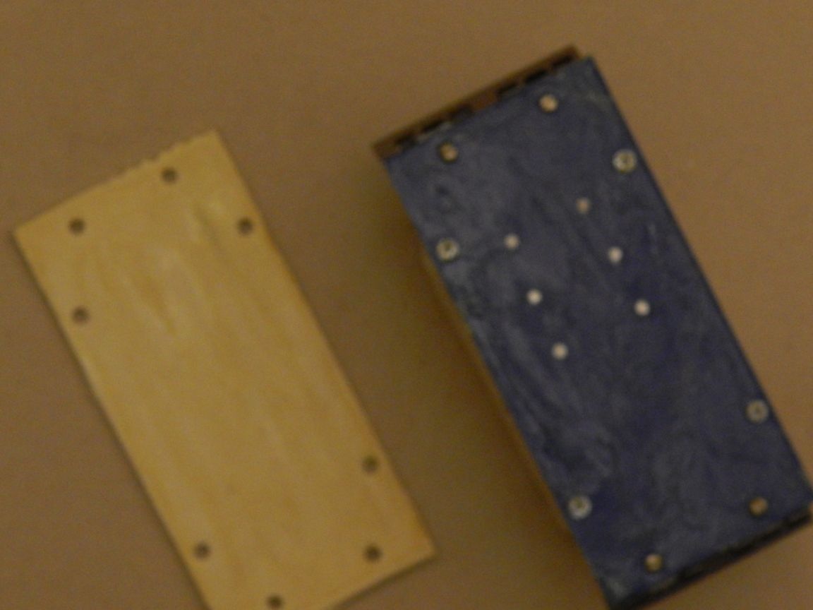
To the sole with the same “Moment” glue we glue a soft material - porous rubber or, as in my case, foamed polystyrene, having punched it in case of dismantling the hole for the fasteners.
The casing of the device I was made of the material of the ventilation pipe.
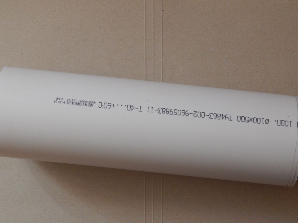
Which I cut along the generatrix, and then with the help of a building hair dryer straightened to a sheet state.
I made a pattern with smooth corners, I did not want to sculpt an angular and “prickly” box to the touch.
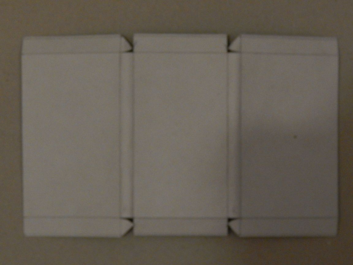
At first, I wanted to use a piece of plastic canister as a casing, but the material turned out to be too liquid. So the casing was glued from PVC with the help of Cosmofen Plus glue (liquid plastic). He bent the plastic locally heating the bend with a Chinese lighter (estimated bend radius 5mm.)
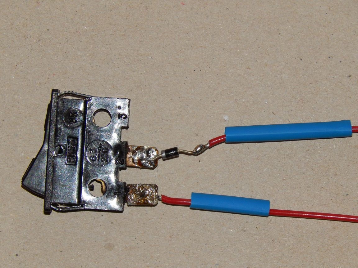
We turn to the electrical part of the machine. To create vibration, a pulsating magnetic field is required, which is created in the coil of the starter, powered by a half-wave rectifier, which is an IN4004 diode whose characteristics indicate current up to 1A and voltage up to 400V. I won’t draw a circuit, everything is connected in series, the direction of turning on the diode is uncritical.
We solder the diode directly to the switch, then we put on heat shrink and isolate the structure.
We insert the switch into the casing and connect the wires.
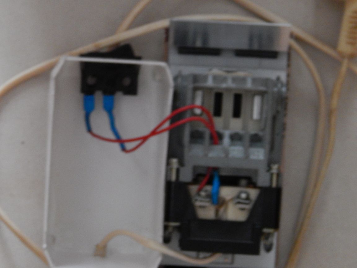
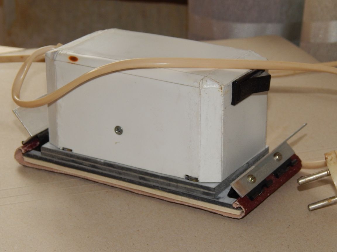
In order not to block the extra corners, the casing is attached directly to the magnetic starter case with two M3 screws.Here is the result:
Now a little about the flaws. The stroke of the machine is only one way, at idle, the starter's armature is drawn to the stator. It was necessary to put two starters in the opposite, and connect the windings for different half-periods, so that both turns were working.
The insufficient power of the machine is due to the fact that it is powered by a half-wave rectifier and the effective voltage on the starter winding is 0.707U of the network (divided by the root of 2), i.e. 155V, and by 2 times the power.
Machine operation video: