

ASTROTIMER v.6.9
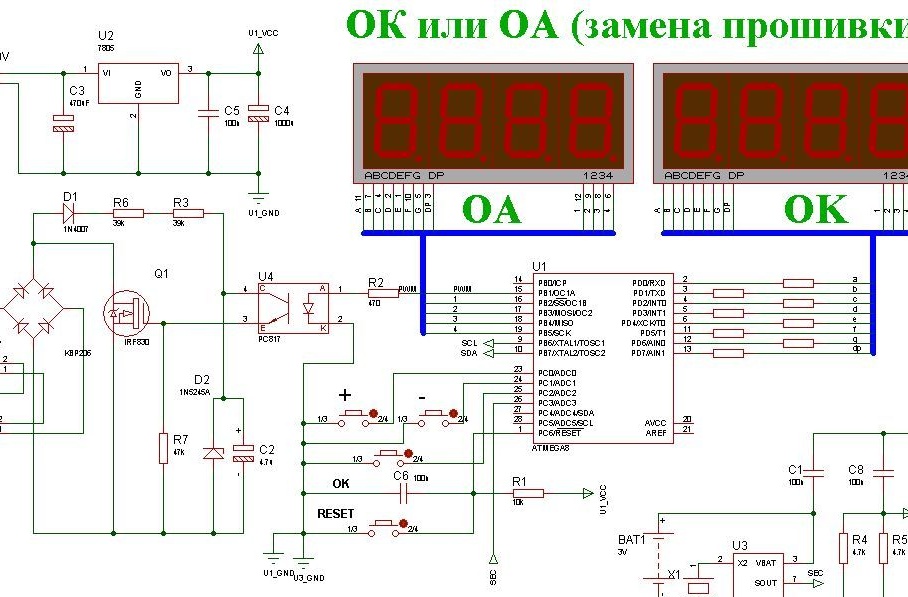
Circuit diagram.
In order to facilitate the work of man and to save electricity, again due to the forgetfulness of man, various automatic machines are used in practice. In particular, automatic switches for outdoor lighting. At the heart of their work, photo optics and comparators are used to reduce the cost of the circuit. The disadvantages are obvious: the photodetector must be installed in a certain place, protected from natural precipitation, dust and extraneous light. Because of this, the device has to be placed in adverse conditions (outdoors) and carefully sealed and insulated, invent protection from extraneous light, moisture and the protection of the photodetector. In winter, the photosensor will freeze and clog with snow.
This device is devoid of these disadvantages. It can be placed directly in the electrical panel next to the contactor (magnetic starter, switch). Power is supplied from the same network.
The device is based on a mathematical calculation of astronomical phenomena, such as sunrise and sunset. In the book of J. Meus “Astronomical formulas for calculators” (M., “Mir” 1988) very accurate formulas for astronomical calculations were published. In 1989, O. Montenbrook and T. Pfleger in the book "Astronomy with a personal computer" laid out the basics of applying mathematical formulas for high-level machine languages Pascal and C.
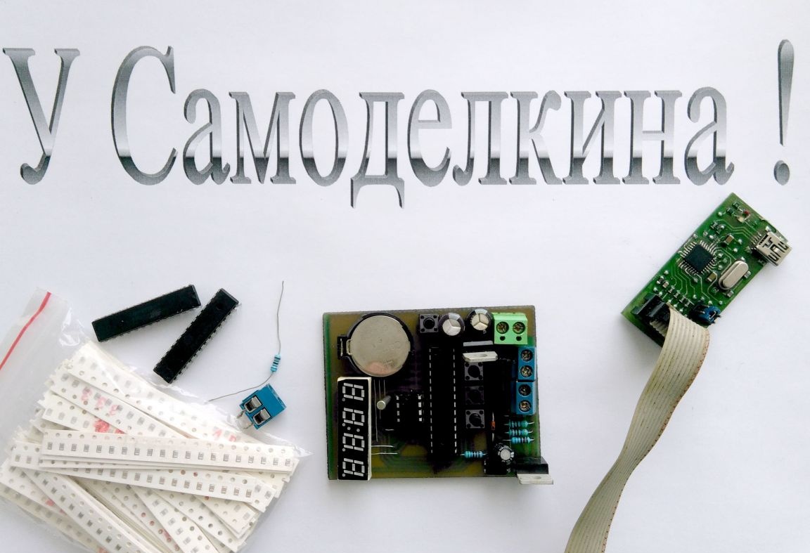
What is a modern computer is a microcomputer. Why not apply this research to AVR microcontrollers. The choice fell on the Atmega8 because of the relative cheapness. Indicator seven-segment LED for four familiarity. A real-time clock (DS1307) with a battery (CR2032), as well as the use of eeprom, allows you to remember settings in the event of a power failure. The scheme is quite simple and can be done by a radio amateur of average skill. The printed circuit board is made by the LUT method, so the tracks are thickened, on the part side, jumpers from a single-core tinned wire with a diameter of 0.5 mm are laid. Chips in a DIP package.The mathematics in the program for calculating sunrise and sunset is quite complicated, but even a microcontroller with a clock frequency of one megahertz copes quickly, that is, when programming a new MK, fuses are installed by default.
Features of the program.
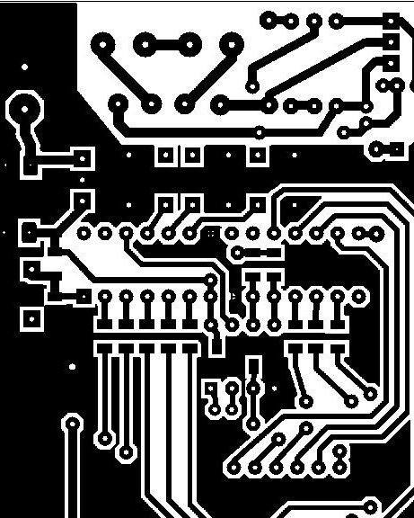
It should be something like this.
The blank is applied to the drawing without touching the surface of the foil. We wrap the ends of the paper on the board so that it does not crawl. On the iron, we set the temperature controller to two. We warm the iron. Under the board we put a sheet of writing (office) paper folded into four and put an iron on top. We warm this "pie" for 10 minutes. Turn the board over and cover with an iron. We warm for another five minutes and then gently, without strong pressure, iron the paper until the board pattern begins to protrude. Carefully put the board in a cold place and allow to cool to room temperature. Soak the cooled board in warm water for 10 minutes. Then carefully separate the paper and in running water we begin to wash off the remaining paper by wiping it with your fingers. Sometimes between tracks, the paper does not wash out completely. Then we prepare a weak solution of vinegar or citric acid, lower the board there. There will be a small zilch, this will dissolve the chalk residues in acid and thoroughly rinse the board. If it suddenly turns out that some conductors are poorly printed, we correct the R-teck radio marker. We poison in the ferric chloride and trickle in the melt of the Rose, then we solder the radio components.
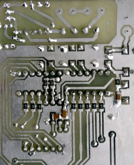
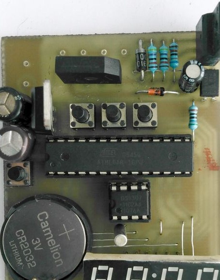
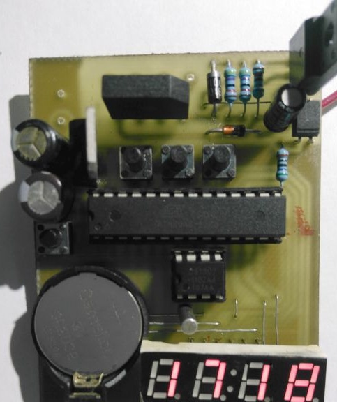
Type of soldered circuit board.
The first inclusion.
After we soldered the circuit board, thoroughly rinse it with a brush moistened first in gasoline and then moistened in acetone. We are drying. We program the microcontroller with two firmware. Flash file with the extension * .hex or * .rom, EEPROM * .eep.
Check for errors and shorties. We turn on the power, first a splash screen with the firmware version appears for a few seconds, during this time the mosfet shutter control capacitor is charged and a program that calculates the time of civil twilight moments is launched, then it will start once a day at 00:00 and a routine deciding to turn on or turn the lights off. This routine runs every minute. Pressing the Enter button, left when the indicator is below, set Lt latitude, Ln longitude, 2n zone, 2018, Г⅂ month, dn day, hr hours, nn minutes, tu off time and tn on time at night to save energy To disable this option, you need to set the same time. Let's say 00 and 00. The next press will switch to the operating mode with time display with a blinking second point. The device is ready to go. The ratings of the parts are tolerable within a reasonable range of + -20%.
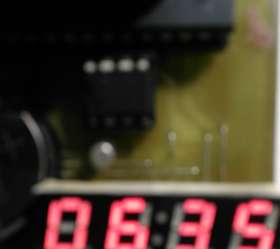
The beginning of daylight
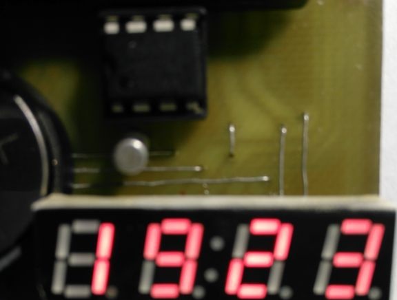
The beginning of the dark
Data calculated for latitude 69, longitude 33, time zone 3 ..
Additional Information.
This applies to those who find it difficult to make a board on their own. We go on, you can pay in several ways, including using a bank card.
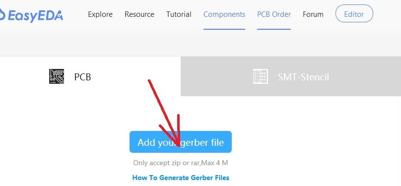
We click on the button "Add your gerber file", select your gerber files, when making the astrotimer, select Proteus_LED_smd (GR) - CADCAM.ZIP directly in compressed form. After a few seconds, we see the board drawing. By default, 10 boards cost $ 2.
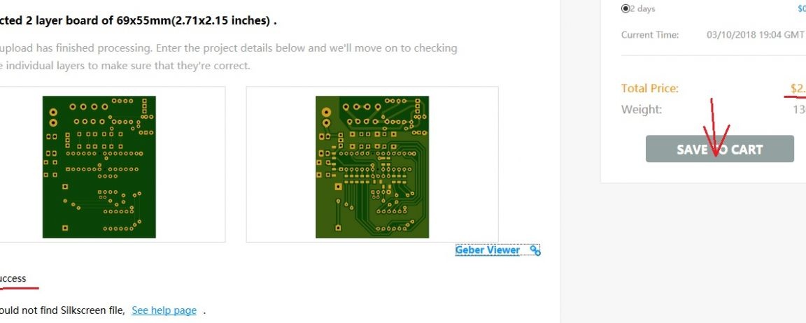
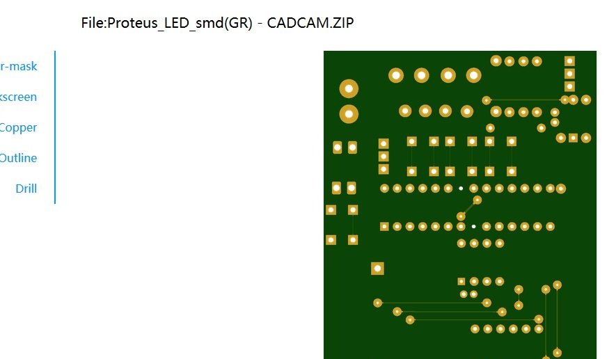
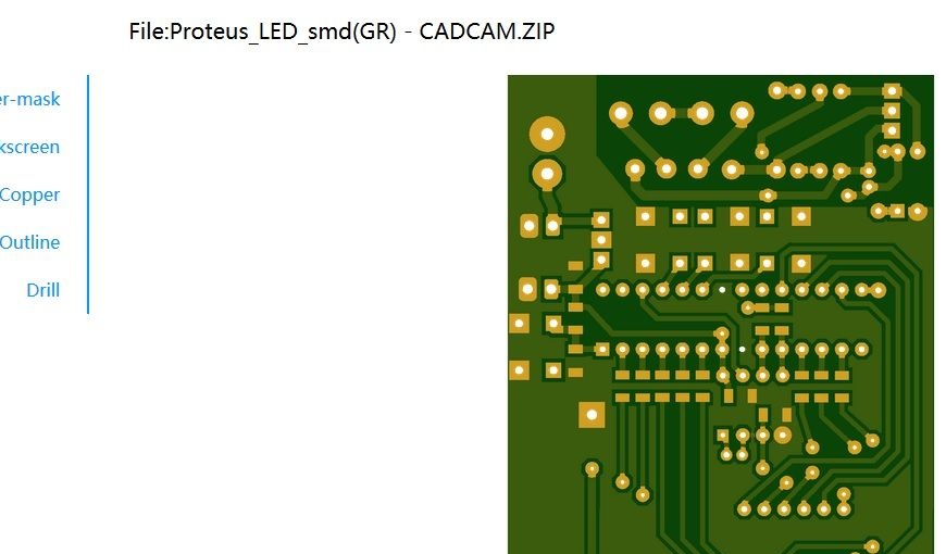
Select “SAVE TO CART” and proceed to checkout. An additional fee for the delivery will appear in the total amount. You can check and view the type of board by clicking "Gerber Viewer", there will be two types of Top and Bottom.
, sources in CodeVisionAVR, projects in Proteus, gerber files, PDF files, drawings are attached. .
Application:
View online file:
View online file:
View online file:
View online file:
View online file:
View online file:
View online file: