

Good day to all! In one of my copyright articles, I showed how to make a very simple EMP emitterwith which you can drive crazy electronics and act on it in every possible way, but that EMP emitter didn’t act on phones with a metal cover, and it was also quite bulky. In today's article, I would like to show you how to make an improved model hand-held EMP emitter do it yourself. This model is not only small and convenient in size but also capable of influencing “shielded” devices (in my case, a xiaomi phone)
Well, homemade very interesting, and able to show beginners in practice the effect of electromagnetic pulses, in general, we will not pull.
Caution! High voltage!
And so for the manufacture of a secretive version of the EMP emitter, we need:
3-6 volt high-voltage converter (took here)
- a tube from a plastic handle
- a piece of rubber or flexible plastic for insulation
dense fabric
needle and thread
wire
-switch without latch
- a power source of 3-6 volts (I use a battery from a quadrocopter with 3.7 volts 500 mah. I really do not recommend using a 18650 battery for these models, since my last module burned out from it, and generally it is advisable to use 3-4 volts for nutrition)
thermal shrinkage
-mini high-frequency coil (I use a coil for picking up a magnetic field from a magnetic tape of cassettes from an old tape recorder, you can try to wind it yourself, but this coil gave the best result, besides it is very small)
-insulating tape
- a tube from a dropper
-Two wires of type "father" (if the battery is like mine)
Of the tools we will also need:
-Soldering iron and small items for soldering
thermal glue
-scissors
-tweezers
-sewing machine
And so the first thing to do is to sew the fasteners on the arm from the fabric, (the sister kindly agreed).
It should turn out something like this, for fixing the device itself and convenient location under the power button (on the glove-bracelet there are traces of thermal glue from past homemade products):
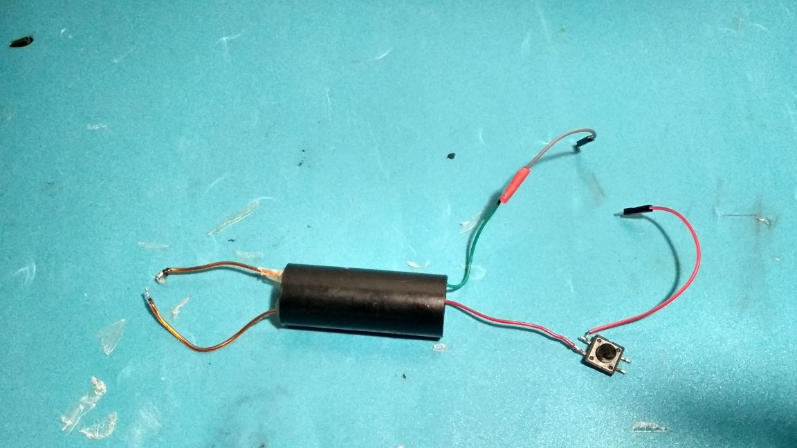
Now take a high-voltage converter and solder a button to one of its input reason, solder a male cable to this button, and solder a male cable to another input wire
(These wires are needed only in the case of the same battery, if you have a normal power source, then use ordinary wires), you should get this diagram:
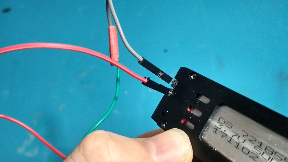
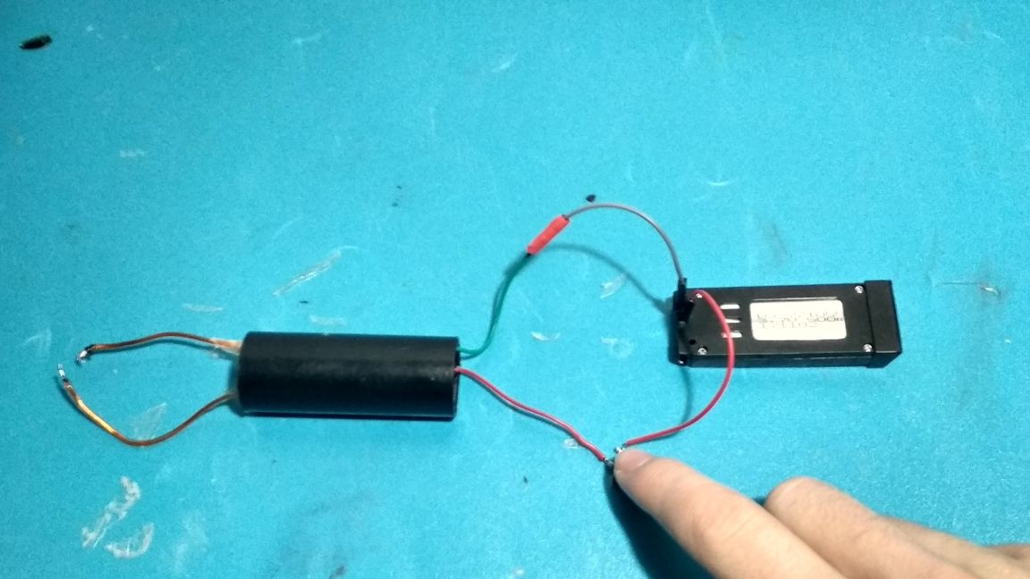
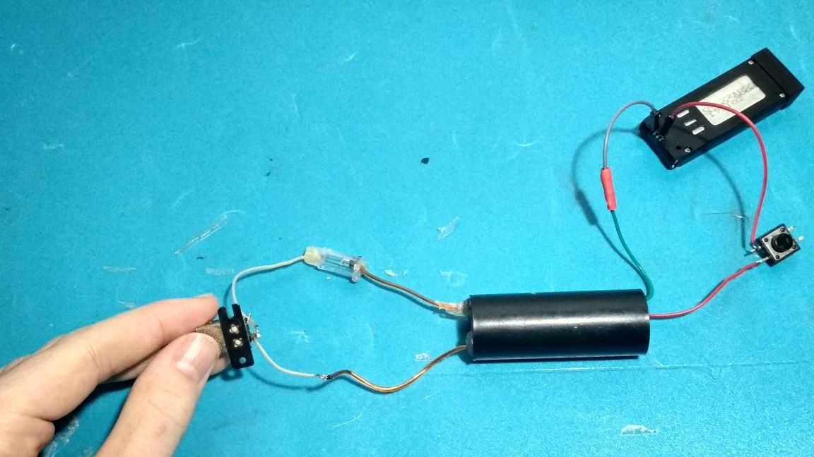
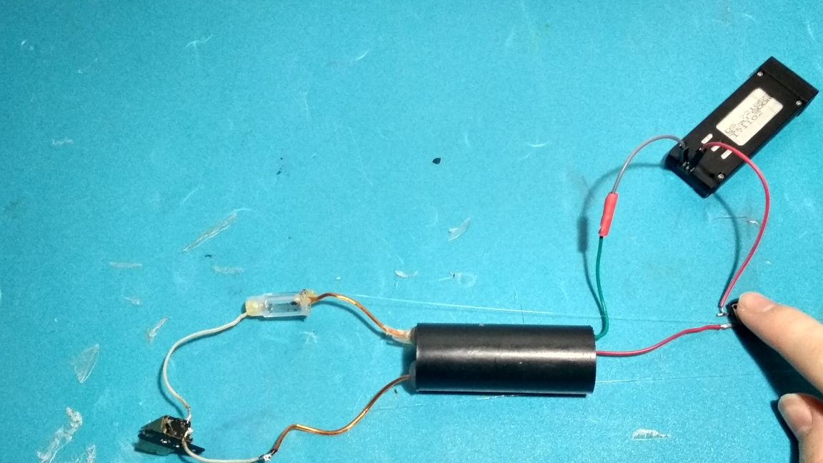
Using the wires, we connect the power source to our high-voltage module, observing the polarity:
Testing:
We place the two terminal wires at a distance of 0.5 - 2 cm, press the button and if an electric discharge occurs between the cantacts, then everything works.
Attention! Be careful! High voltage!
Take a regular tube from the handle and cut off a piece of 2-3 cm long with a small file or a soldering iron:
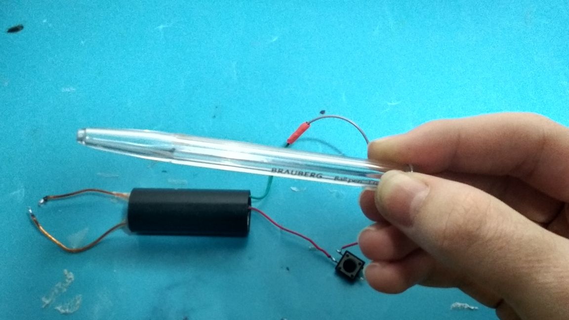
We insert one of the output wires of the high voltage into our workpiece, but not deeply, the wire should go inside no deeper than 5 mm, then we fix everything with thermal glue:
We take our high-frequency coil to remove the magnetic field from tape tapes. On such coils, there are usually 4 contacts, since there are usually 2 contacts, use a multimeter to ring them and determine which contacts belong to one coil, then solder them in a sequential manner (this will be the greatest resistance than from parallel soldering) then solder to two the remaining contacts are two wires, after which one of them is also inserted into the piece from the plastic tube, and the second wire is soldered to the remaining high-voltage wire.
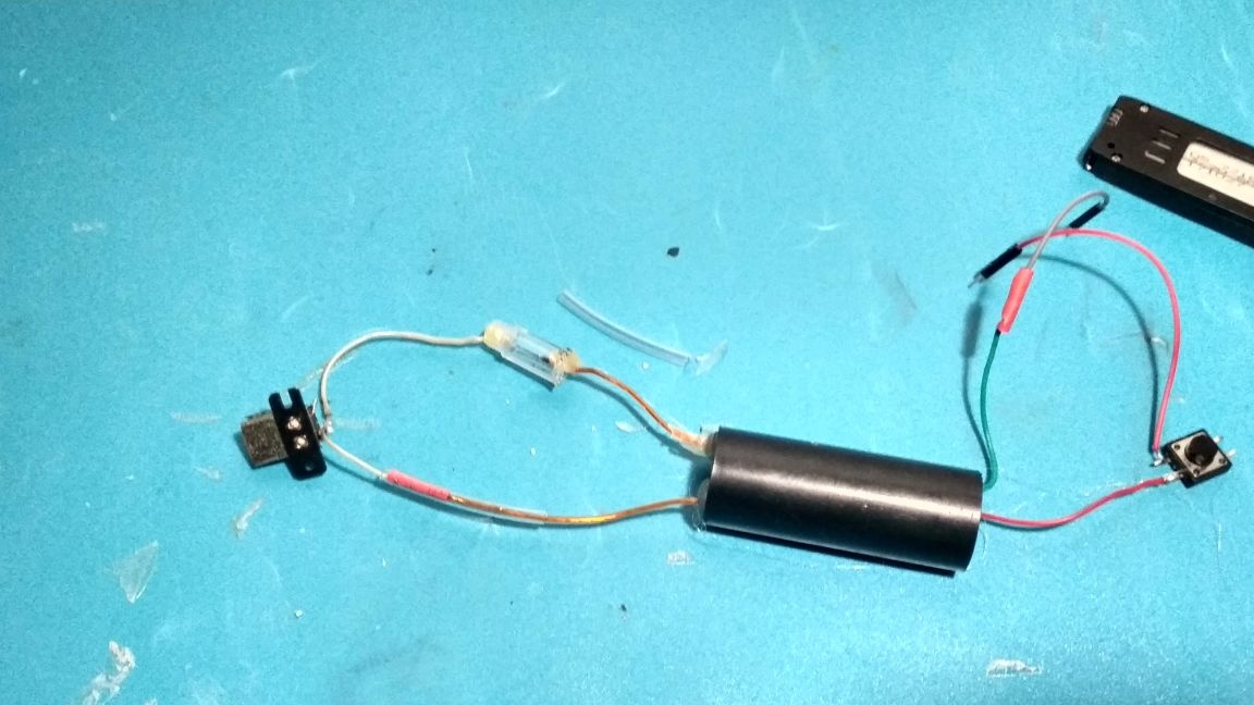
Now you need to make the contacts fit: by trial, we adjust the distance between the wires inside the tube, you need to set the maximum distance, but so that the discharge occurs anyway, after finding this distance we fix the wires with thermal glue, but so that air can pass into the tube, this is important , experiments showed that if there is a hermeticization, then after several discharges they cease to occur, most likely this is due to the interaction of the current with the electric field.
In general, it should turn out like this:
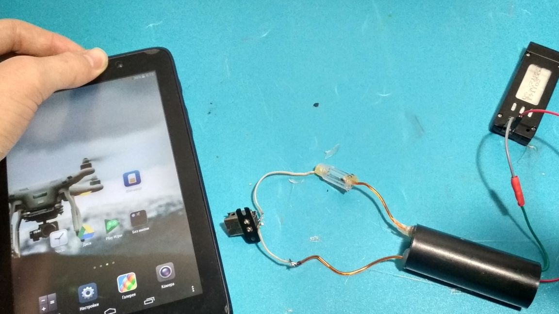
We test our workpiece on an electronic device (in my case, it’s still a tablet, since I’m taking it off to the phone), bring it to the coil and press the button, if the tablet starts to go dull and turn on applications spontaneously and generally go crazy, then everything is done correctly:
Now you need to insulate all the contacts with the help of heat shrinkage, and on the high-voltage wires we put pieces of tubes from the dropper, it is also desirable to wind everything up with electrical tape. And yes, you need to do all this with the power source disconnected from the high voltage:
Well, we begin the final assembly of our glove:
First, glue our power source to it, glue it so that it is convenient:
Then we glue our module, input wires to the palm:
Glue a piece of rubber or flexible plastic next to the high voltage (of course, it is best to completely isolate the entire glove in this way):
Glue a high-frequency coil on our insulation and carefully place the wires:
The arrester is also glued as neatly as possible and also preferably on the insulation (I would have glued it, but I didn’t have the length of the wire) of course it doesn’t look very neat, probably the thermo glue and fabric and hands are not compatible from that place:
Then we glue our button on the edge of the entire glove, approximately like this:
That's it! Our EMP glove is ready and it remains only to test it! We put on a glove on our hand, once again we check the insulation and testly press the button, then we take any phone, turn it on and bring it to the coil, while the phone even with a metal cover starts to dumb terribly, and so with almost all electronic devices, the calculator generally turns on , the range with my battery is about 5-10 cm from the coil. Of course, this homemade product is more suitable for entertainment than for practical use, but such a simple homemade product can clearly show the beginners in the world of physics and electronics the effect of electromagnetic pulses on microcircuits and conductors, which are not so easy to show.
Here is a detailed video with tests and assembly:
Well, thank you all for your attention!