

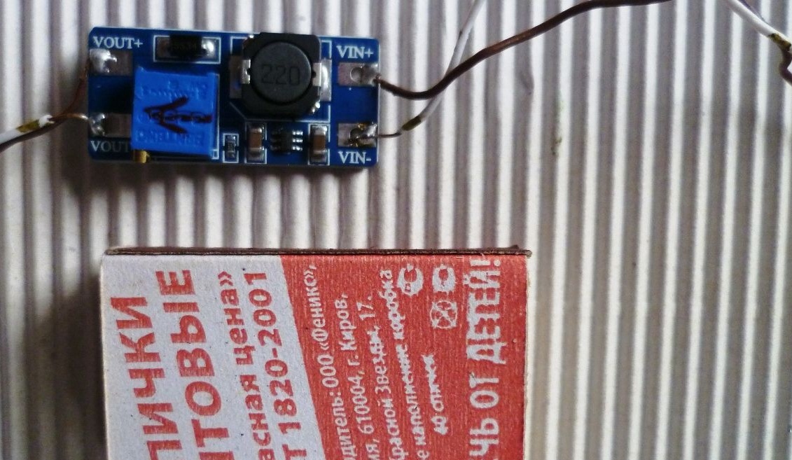
Greetings to all the masters. Surely in every home are used batteries from faulty phones. These batteries can be successfully given a second life by using them as a power source for children's toys, flashlights and the like. Lithium-ion batteries are designed mainly for a voltage of 3.7 Volts, which means they can replace three alkaline batteries of the AA or AAA format. Moreover, we will have for a long time a rechargeable power source. If we need to have a voltage of 5 to 28 Volts, we connect a raising board (the Chinese have a large selection of inexpensive DC-DC modules now).
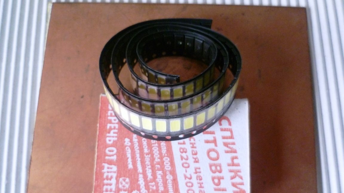
Since ancient times, several lithium-ion batteries from old phones have been littering me on the shelves. As a result of the test, the tester also turned out to be quite alive. I needed a compact flashlight, somewhere to quickly highlight in the garage or in another dark place. It was decided to make an LED flashlight based on batteries from old-age phones. LEDs applied type SMD 5730.
The list of tools and materials
lithium-ion battery 3.7V \ 700mA-1pcs;
-connecting wires;
soldering iron;
-tester;
-transparent plastic box from the video cassette -1pcs;
White LED SMD 5730-15 pieces;
-Resistor 2 Ohm-1pc;
- double-sided foil textolite;
-button switch from the flashlight-1pc;
-USB connector -1pcs;
Charger from the phone.
Step one. Putting a lantern.
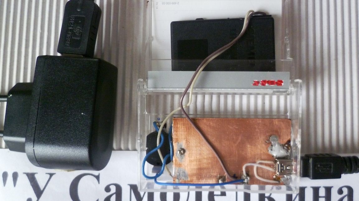
Using a cutter, I made a printed circuit board from a piece of double-sided foil textolite (or can be etched chemically). The printed circuit board will at the same time serve as a heat sink for the LEDs. Its dimensions are arbitrary, depending on your lamp housing. The distance between the tracks is best done within 3 mm.
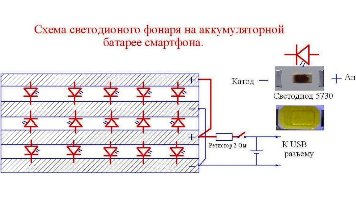
Next, we clean the board with small emery and tin the paths. Solder the LEDs according to the scheme. You can solder with a soldering iron or hot air gun or just on the iron. On a preheated iron, carefully lay the board with the LEDs pre-arranged. When the solder melts, adjust the position of the LEDs if necessary. After carefully remove the board for cooling.
Solder the connecting wires and jumpers. On the back of the board, solder the USB connector to charge the battery.
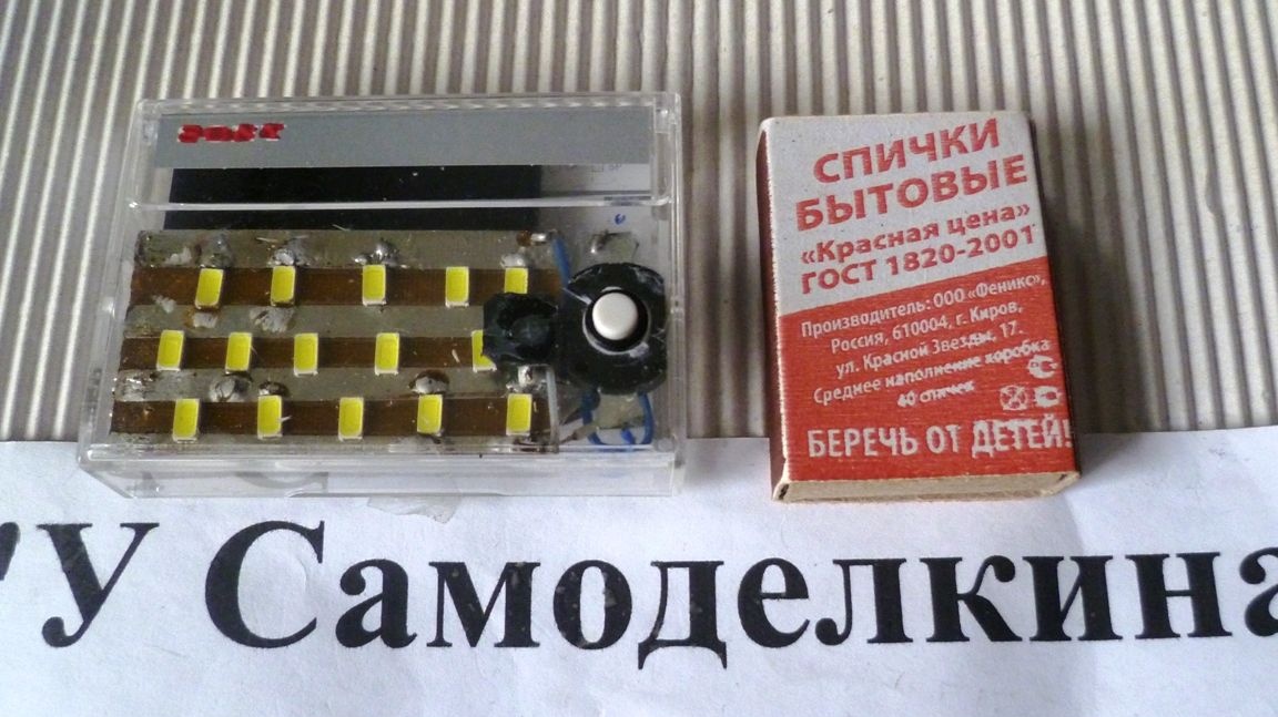
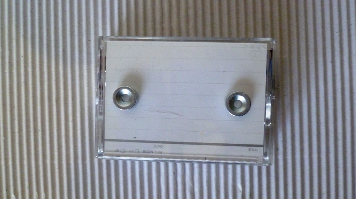
In the transparent plastic box from the video cassette we make holes for the switch and the USB connector, then we install the circuit board and the flashlight battery is ready. On the back of the box, two magnets were put on glue. This will make it possible to attach a flashlight to the iron plane in the machine, control cabinet, etc., if necessary.
Step Two Testing the lantern.
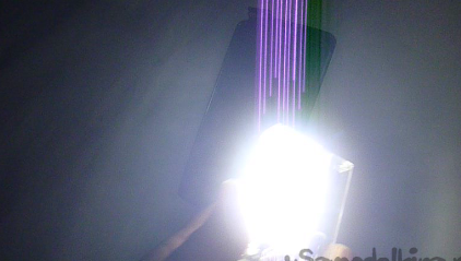
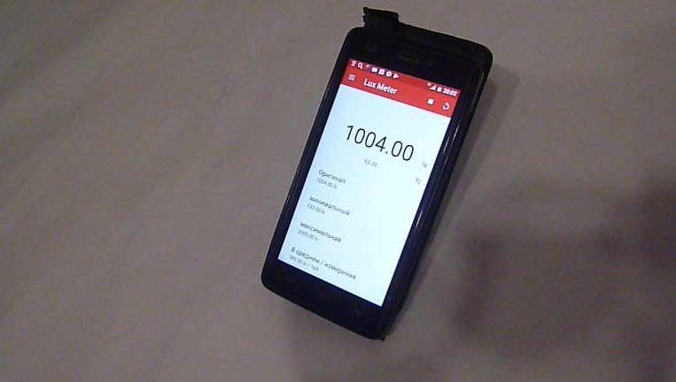
It was interesting to measure the luminous flux of the flashlight. Using the Luxmeter application installed on the phone, I made approximate measurements. At a distance of 1 meter, the luminous flux was 1000 lx, which is comparable to a 70W incandescent lamp. Not bad for such a crumb. The current consumption was 200 mA.
TP4056 lithium battery charging board, which is fashionable in our time, is not necessary to use in this case, since the charge controller is mainly installed in the battery. This device is rated for a low voltage of 2.2 Volts-Upper 4.3 Volts. On the other hand, the TP4056 module has its own USB connector that allows you to charge the battery from any source with a voltage of 5 volts. This flashlight can also be used in the form of a night light, a backlight in a closet or a small room (by connecting a normally-open reed switch instead of a switch, install a magnet on the door). In general, that is enough fantasy. More details can be seen in the video
I wish you all health and success!