
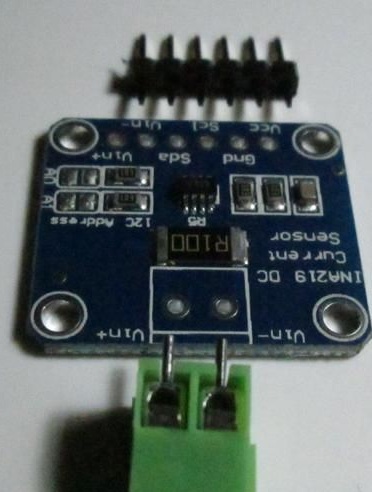
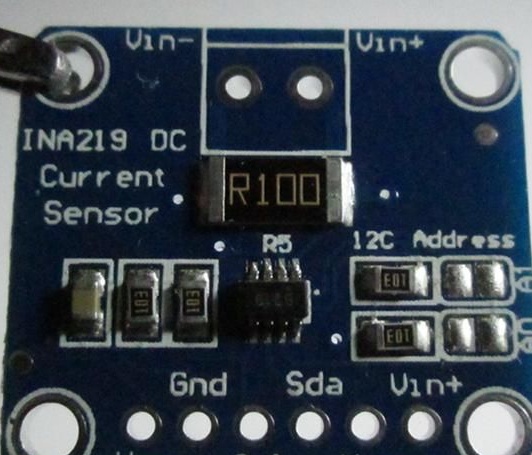
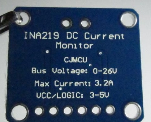
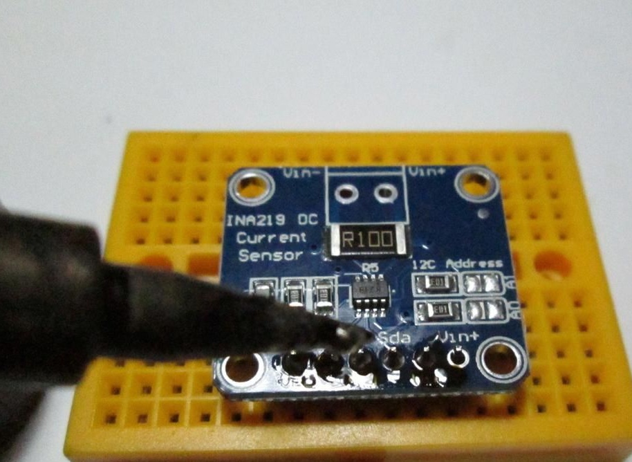
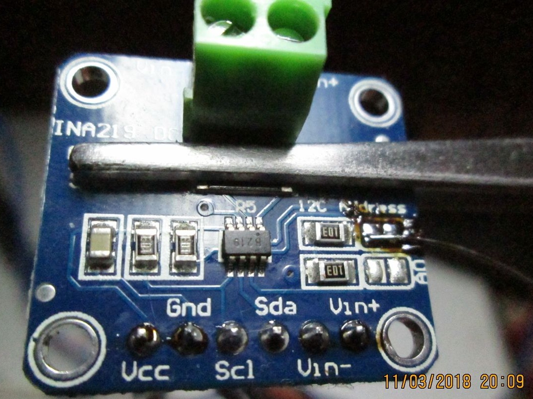
The main parameters of the board are indicated on the board itself.
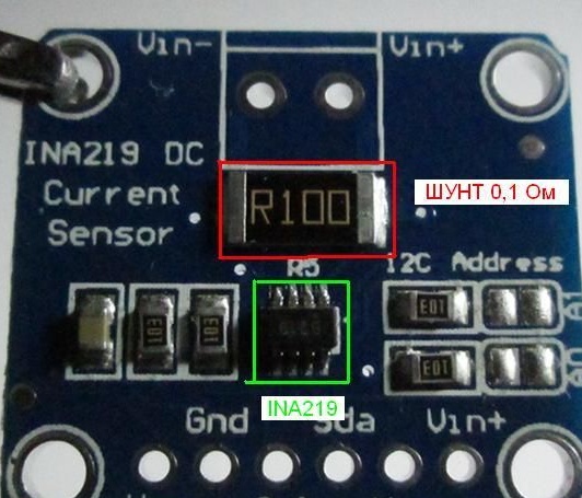
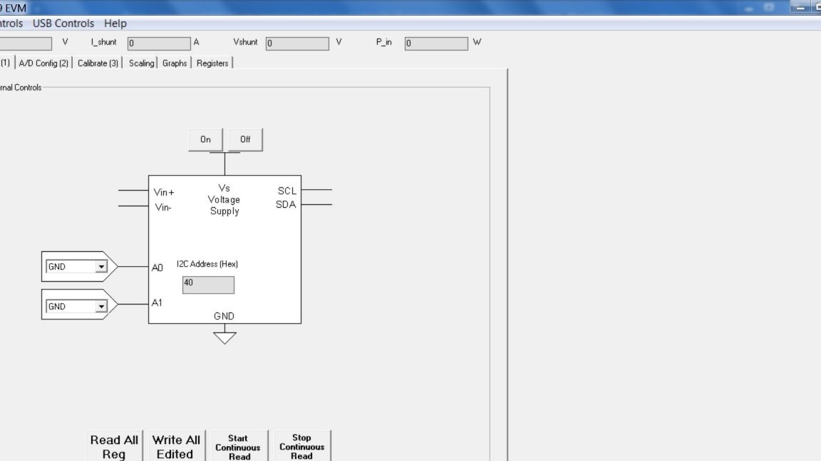
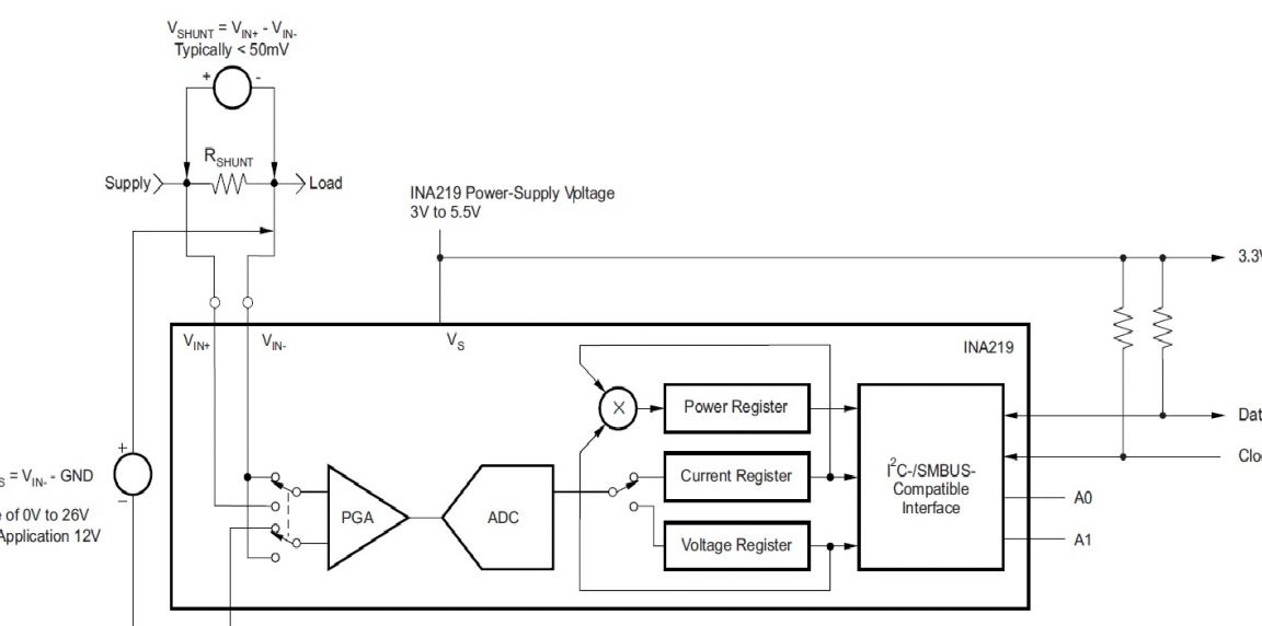
The main element on the board is the INA219 chip. The INA219 chip, despite its small size and small number of pins, has great capabilities. The microcircuit measures the voltage on the shunt (at the terminals Vin + and Vin_) - a resistor with a low resistance and on the Vin-pin relative to the GND pin, in turn. The calculation results are written into registers, then they are transmitted to the microcontroller via the I2C communication bus. A shunt with a resistance of 0.1 ohms is installed on the board. The voltage in the chip measures the analog-to-digital converter of the ADC. The ADC can operate in 9, 10, 11, 12 tibit modes. The mode of operation of the chip is configured by changing the configuration register. The manufacturer has a free program, INA219 EVM, for configuring the INA219 chip. Program File - sboc271.zip
Datasheet file on the INA291 chip -
View online file:
The microcircuit has the ability to adjust the accuracy of its measurements, in other words, it is possible to calibrate the measurement results.
To verify the operation of the board on the INA219 chip, the following circuit was assembled.
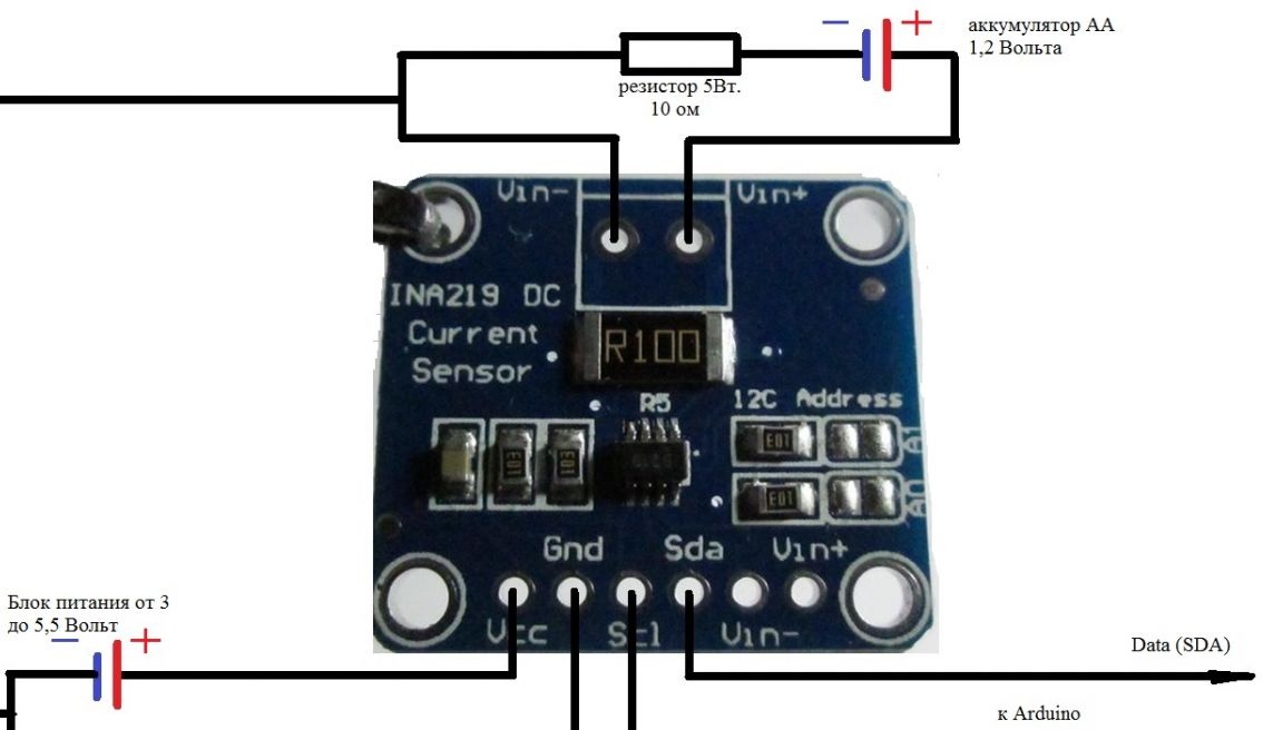
Power on the board with the INA219 chip must be supplied from the board Arduino or other power source.
To work with the board on the INA219 chip in the Arduino IDE programming system, we need a library. Internet searches yielded a positive result. I found several libraries, but it worked for me with only two.
The first library from Adafruit was found - Adafruit_INA219-master.zip
It is working, but I could not connect to the board with the INA219 chip when I changed the I2C bus address. By default, a board with an INA219 chip has an I2C 0x40 bus address. It also does not allow you to configure the operating mode of the INA219 chip.
The second library was devoid of the shortcomings of the first. The second working library is Arduino-INA219-master.zip
How are libraries installed in the Arduino IDE programming system? You can get the answer to this question from my articles or from information posted on the Internet.
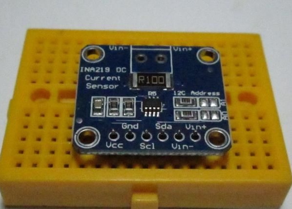
I want to use the board with the INA219 chip for experiments. It will be more convenient for me to work with it if I solder the connector and pins of the BLS onto the board.
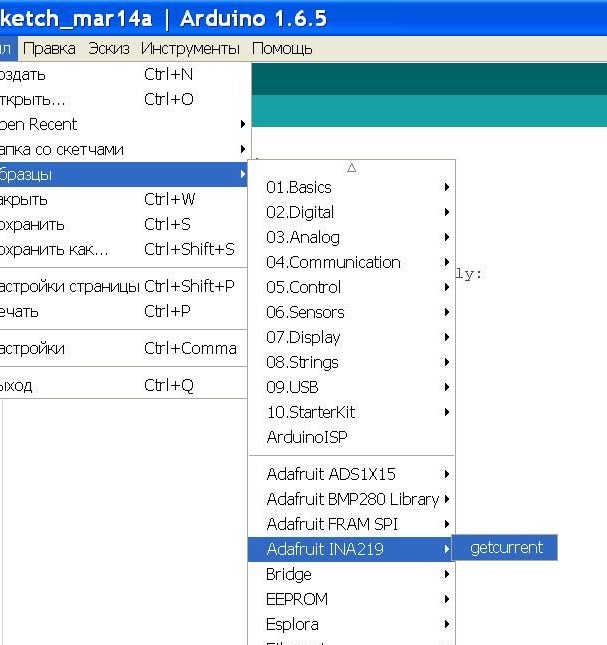
I assembled the circuit, connected the Data (SDA) and Clok (SCL) pins to the Arduino UNO board. Connect the Data output (SDA) to the A4 connector, connect the Clok (SCL) output to the A5 connector of the Arduino UNO board. Then open the Arduino IDE program. I have already installed libraries. We open an example of the first library.
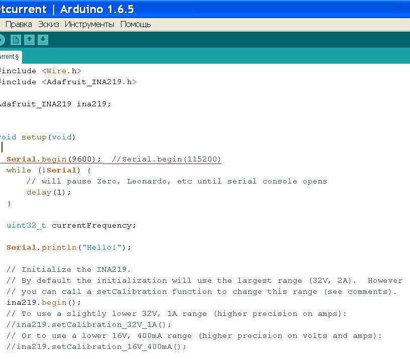
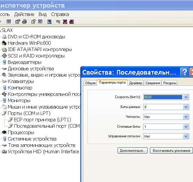
I changed line 9 in the code instead of 115200, set 9600. Otherwise, scribbles will appear in the serial port monitor instead of numbers and letters. I also configured the computer's com port to 9600. This was tested by me in practice.
We compile the getcurrent example. We load data into the controller of the Arduino UNO board. Open the serial port monitor in the Arduino UNO program and see the measurement result obtained from the INA219 chip.
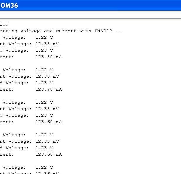
The measurement result of the INA219 chip was accurate.
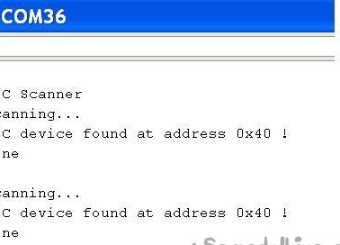
Next, I decided to change the address of the I2C bus. And before that, I determined the I2C bus address of the INA219 board with the help of a sketch, as I did in the article “Home weather station on GY-BMP280-3.3 and Ds18b20»
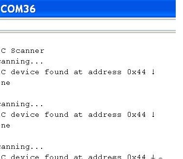
To change the I2C bus address of the board from the INA219 chip, I soldered the jumper and determined a new I2C bus address.
Then I downloaded the example from the second library.
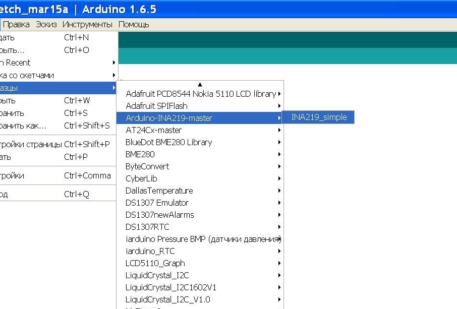
In order for the compiled code (converted into a form suitable for writing to the microcontroller of the Arduino UNO board) to be able to work with the board on the INA219 chip with the address 0x44, you need to change the line ina.begin () in the example; to the string ina.begin (68);
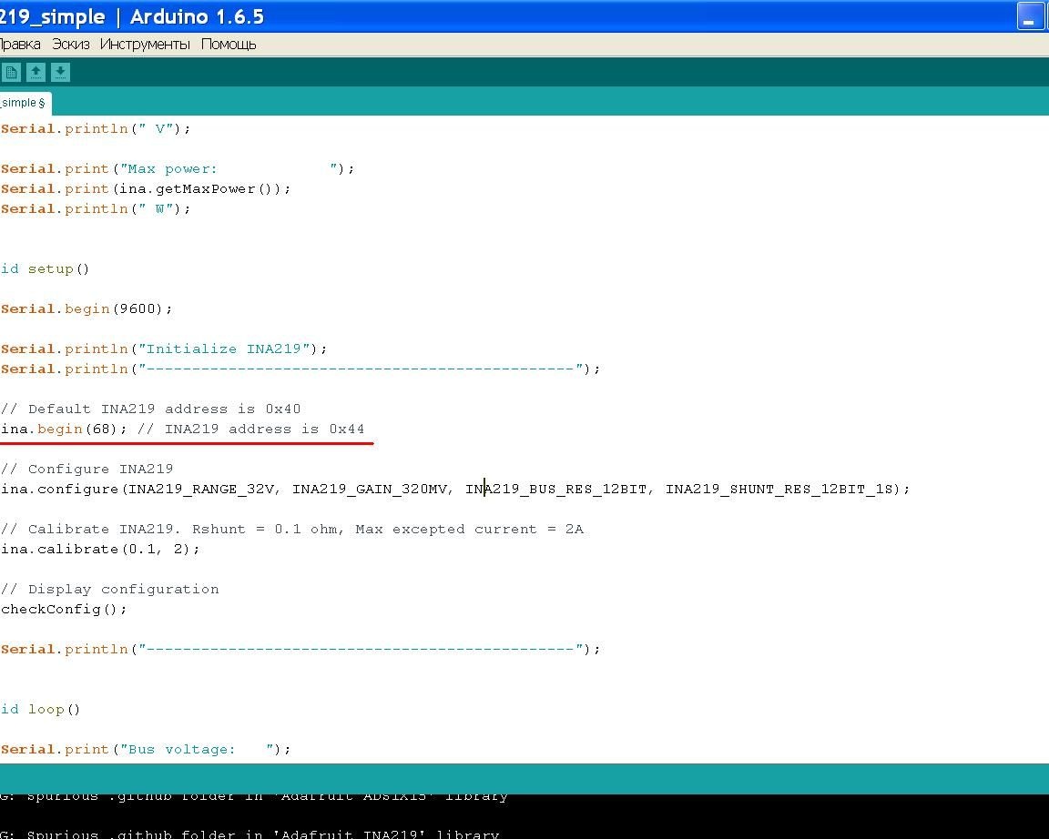
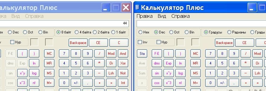
Why 68? And because 68 = 0 x 44, 68 is a number in the decimal number system, 0 x 44 is a number in the octal number system.
To translate numbers, you can use the standard calculator.
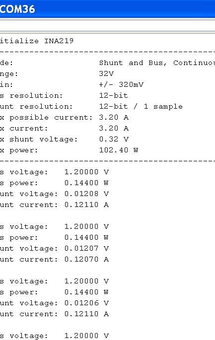
After changing the compilation line of the example, flashing the code in Arduino UNO in the serial port monitor, I saw the following.
Good luck to everyone in your endeavors and deeds!
Cost: ~ 80