Recently I received a set of rechargeable nickel-metal hydride (NiMH) batteries for the Bosch 14.4V, 2.6Ah screwdriver. Batteries actually had a small capacity, although they were operated under load only for a short time and had a small number of discharge (work) - charge cycles. For this reason, I decided to disassemble the batteries, perform their element-by-element measurements to determine the characteristics and possible recovery, use the "surviving" elements in others homemade requiring a large current output in a short time. This work is described in stages in the note “Automatic battery discharge device».
After disassembling the battery
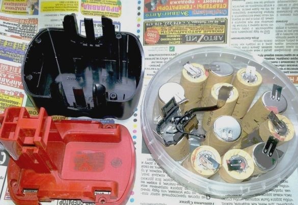
A preparatory discharge of the elements on the specified device was performed, with a control over the minimum residual voltage of 0.9 ... 1.0 volts, to exclude a deep discharge. Next, a simple and reliable charger was required to fully charge them.
Charger Requirements
Manufacturers of NiMH batteries recommend performing a charge with a current value in the range of 0.75-1.0C. Under these conditions, the efficiency of the charging process, most of the cycle, is as high as possible. But by the end of the charging process, the efficiency decreases sharply and the energy goes into heat generation. Inside the element, temperature and pressure rises sharply. Batteries have an emergency valve that can open when pressure increases. In this case, the properties of the battery will be irretrievably lost. Yes, and the very temperature has a negative effect on the structure of the electrodes of the battery.
For this reason, for nickel-metal hydride batteries it is very important to control the modes and condition of the battery when charging, the moment the charging process ends, to prevent overcharging or destruction of the battery.
As indicated, at the end of the NiMH battery charging process, its temperature begins to rise. This is the main parameter to turn off the charge. Usually, a temperature increase of more than 1 degree per minute is taken as a criterion for the termination of charge. But at low charge currents (less than 0.5 ° C), when the temperature rises slowly enough, it is difficult to detect. An absolute temperature value can be used for this. This value is taken 45-50 ° C. In this case, the charge must be interrupted, and renewed (if necessary) after cooling the element.
It is also necessary to set a charge time limit. It can be calculated by the battery capacity, the amount of charging current and process efficiency, plus 5-10 percent. In this case, at normal process temperature, the charger is turned off at the set time.
With a deep discharge of the NiMH battery (less than 0.8V), the charge current is preliminarily set at 0.1 ... 0.3C. This stage is limited in time and takes about 30 minutes. If during this time the battery does not restore the voltage of 0.9 ... 1.0 V, then the cell is unpromising. In the positive case, charge is then performed with an increased current in the range of 0.5-1.0C.
And yet, about the ultrafast battery charge. It is known that when charging up to 70% of its capacity, the nickel-metal hydride battery has a charging efficiency close to 100 percent. Therefore, at this stage it is possible to increase the current to accelerate its passage. Currents in such cases are limited to 10C. High current can easily lead to overheating of the battery and the destruction of the structure of its electrodes. Therefore, the use of ultrafast charge is recommended only with constant monitoring of the charging process.
Charger manufacturing process for NiMH battery reviewed below.
1. Establishing baseline data.
- Charging the cell with a constant current value of 0.5 ... 1.0C to the rated capacity.
- Output current (adjustable) - 20 ... 400 (800) ma.
- Stabilization of the output current.
- Output voltage 1.3 ... 1.8 V.
- Input voltage - 9 ... 12 V.
- Input current - 400 (1000) ma.
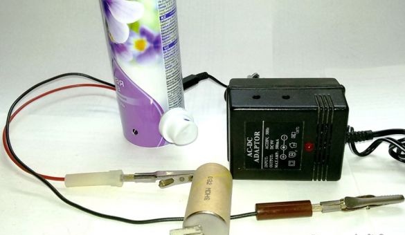
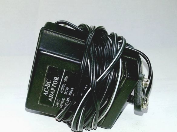
2. As a power source for the memory, we select a mobile adapter 220/9 volts, 400 ma. It is possible to replace with a more powerful one (for example, 220 / 1.6 ... 12V, 1000 ma). Changes in the design of the memory will not be required.
3. Consider the charger circuit
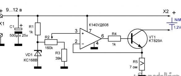
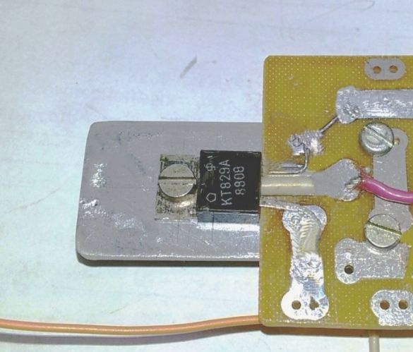
A design variant of the battery charger is a stabilization and current limiting unit and is made on one element of an operational amplifier (OA) and a powerful composite n-p-n transistor KT829A. The charger makes it possible to adjust the charge current. The stabilization of the set current occurs by increasing or decreasing the output voltage.
At the junction point of the resistor R1 and the zener diode VD1, a stable reference voltage is generated. By changing the voltage value taken from the potentiometer R2 of the resistor divider at the non-inverting input of the operational amplifier (pin 3), we change the value of the output voltage (pin 6), and therefore the current through VT1. Resistor R5 limit the current in the circuit of the rechargeable battery. The change in the voltage drop at R5 when the charging current deviates through the feedback (OOS) to the inverting input of the op-amp (pin 2), corrects and stabilizes the output current of the charger. Installed R2 current will be stable until the end of charging of this and subsequent batteries of the same type.
This current stabilizer circuit is very versatile and can be used to limit the current in various designs. The circuit is easy to repeat, consists of simple and affordable radio components, and when installed correctly, they immediately begin to work.
A feature of this circuit is the ability to use available operational amplifiers with a supply voltage of 12V, for example, K140UD6, K140UD608, K140UD12, K140UD1208, LM358, LM324, TL071 / 081. The KT829A transistor is the main power element and all current passes through it, therefore it is necessarily installed on the heat sink. The choice of transistor is determined by the required charging current set to charge the battery.
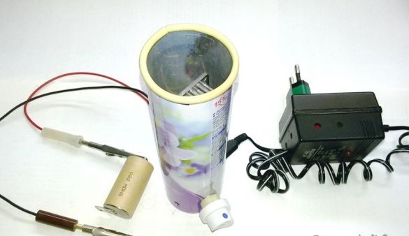
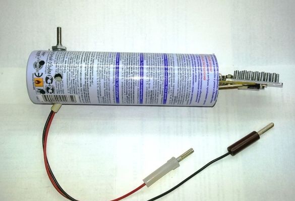
4. Select the housing for the charger. He will determine the shape, design, heat removal conditions and appearance of the memory. In this case, an aluminum aerosol can was selected. We remove its upper part.

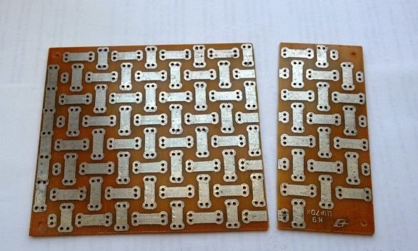
5. We cut off from the universal mounting plate a part equal in width to the inner diameter of the cylinder. It is preferable to tight, without pitching, the entry of the board into the cylinder.
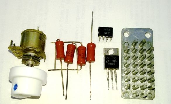
6. We complete the memory with parts according to the scheme. The aerosol cap is well sized as a potentiometer knob.
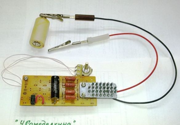
7. We fix the transistor on the radiator and install the radiator on the edge of the board, according to the photo.
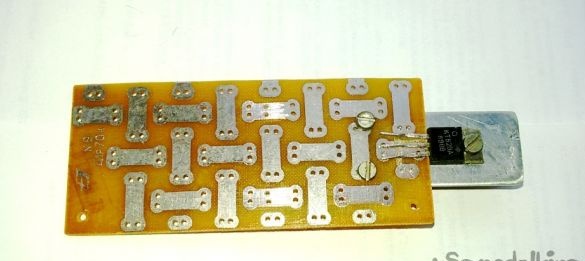
8. Solder the transistor leads to the pads of the board.
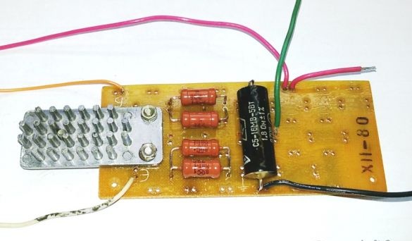
9. Solder the resistance, limiting the maximum possible battery charge current. Since the entire charge current passes through the resistor R5, for the best cooling of the resistor, it is drawn from the widely used (MLT-1) four parallel-connected resistors of 22 ohms with a power of 1 W each. Additionally, a 1.8 ohm 5-watt resistor is installed in series. The total resistance of R5 was about 7 ohms (average power 4 watts). The resistance and equipment of the resistors depend on the planned charging current and the availability of parts from the manufacturer.
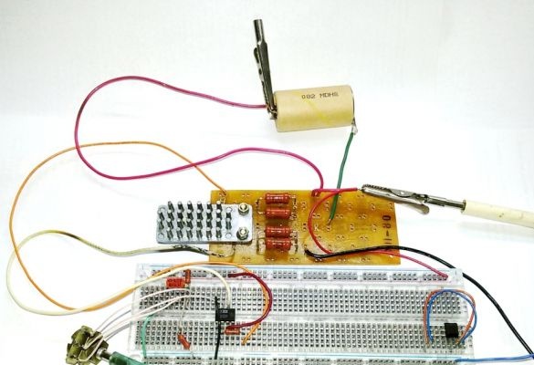
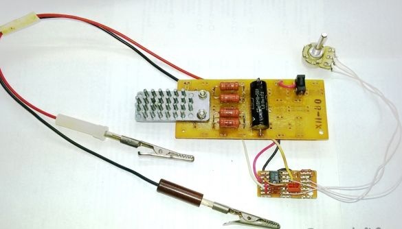
10. Assemble the control part of the memory on a breadboard circuit board. We connect the manufactured power unit of the charger and connect the load - a rechargeable battery. To check the operation and debug modes, connect the memory to an adjustable power supply. We check the range of adjustment of the charging current, if necessary, we select the value of resistors R2 and R3.
11. Transfer the control part of the memory to the working scarf
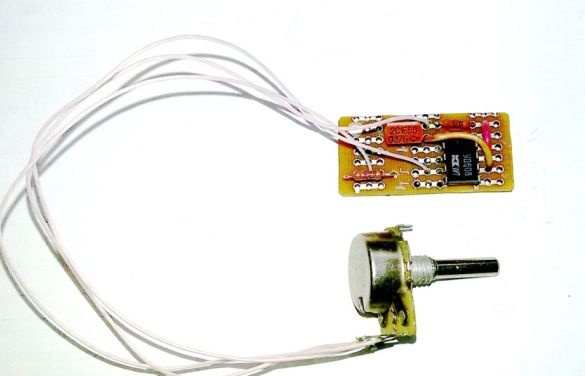
and attach it to the power unit.
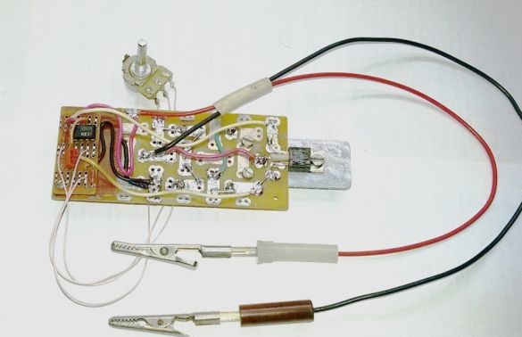
12. On the board, on the side, install the socket for connecting the power supply of the charger (adapter or other power supply).
13. Install the memory in the housing, placing the radiator in its upper (open) part.
Pre-drill a series of holes with a diameter of 6 mm in the lower cylindrical part of the housing. The working position of the charger housing is vertical, therefore, in it, similar to a chimney, natural traction is created. Air heated by resistors and a radiator rises from the housing upward, drawing cold into the lower holes. Such ventilation works effectively, because significant heating of the radiator with 2, 3-hour operation of the charger is practically not felt by the heating of the case.
14. The charger is assembled with a working set and tested under load, fully charging a dozen batteries. The memory works stably. At the same time, the estimated charging time, as well as the battery temperature, is periodically monitored to disable the charger at critical values. Using "crocodiles" to connect the battery allows you to connect to the memory control ammeter (multimeter) to adjust the charging current. When charging subsequent elements of the same type, an ammeter is not needed.