

Hi, the inhabitants of our site!
Today I will show you how I put together a powerbank with an on / off indication, the charging process and the charge level of the li-ion battery.
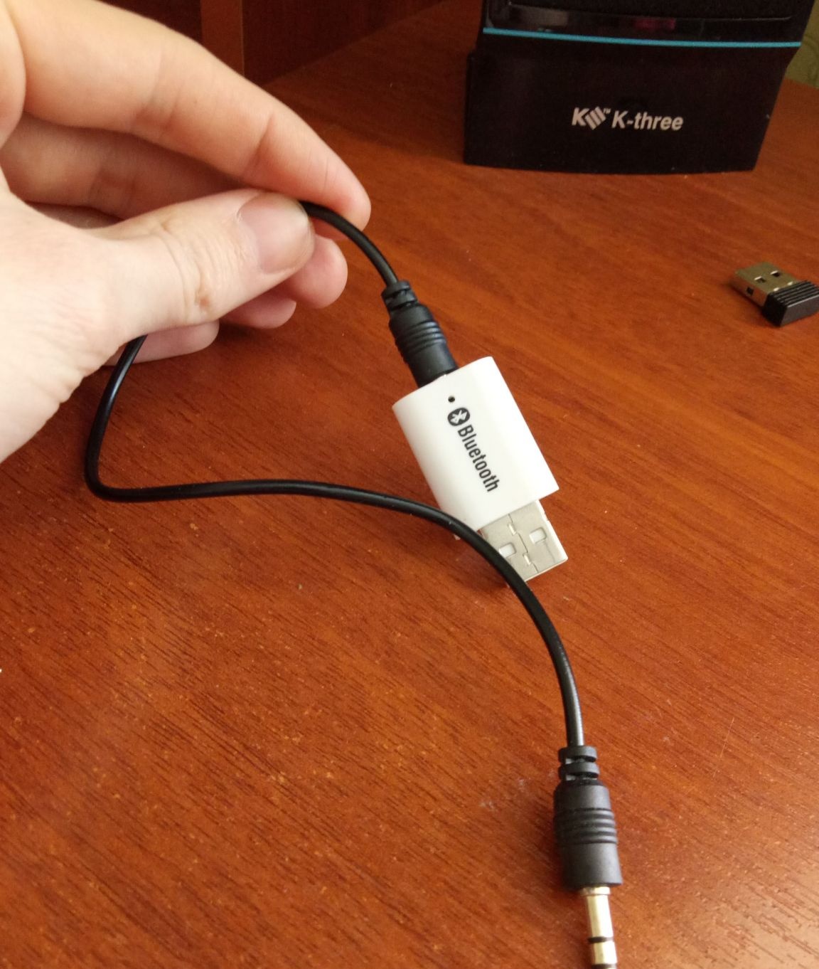
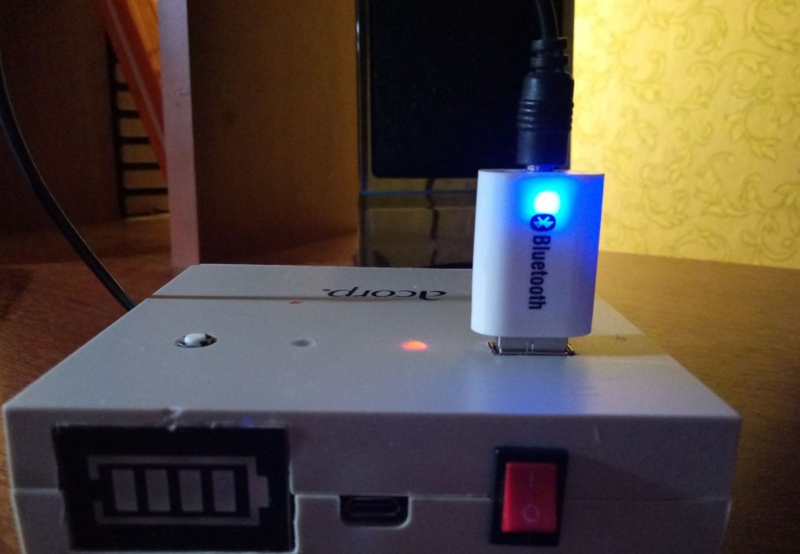
As you know, almost all powerbanks sold in offline and online stores do not have an on / off button. They are turned on, as a rule, when the consumer is connected, and are turned off when they are removed from the usb connector. But if the device connected to the bank uses a small amount of energy, then the bank either "does not see it" or turns on the power for a short time, and then turns off. Due to this principle of operation of these portable chargers, it is impossible to use them as power for usb gadgets with low current consumption. Most recently, I (thanks to all the well-known Chinese online store) got such a usb gadget - a stereo Bluetooth audio adapter. The appearance of which is shown in the photo.
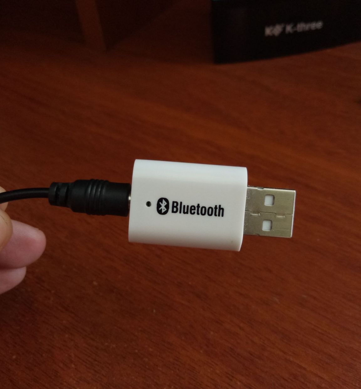
It is powered by 5 volts, it consumes a current of about 5-10 mA in operation, the banks do not recognize such a load and simply do not turn on. Judging by the reviews of the online store, such a gadget is purchased mainly by motorists to connect to a car radio that does not have Bluetooth technology, in this case, power is taken from the usb connector of the radio. I plan to use it at home by connecting to the speakers via aux. In order to avoid extra wires (including for powering the Bluetooth adapter), it was decided to assemble a powerbank specifically for this device.
Tools and materials:
1. Li-ion battery
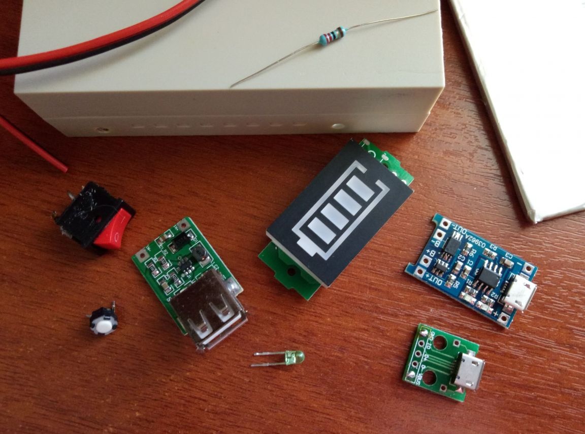
2. Plastic box (future body of the bank)
3. Dc-dc step up (step-up voltage converter)
4. Battery charge / discharge controller li-ion
5. Mini switch
6. usb connector
7. Micro button
8. LED indicator of a charge level
9. Wires
10. Multimeter
11. Soldering iron
12. Solder
13. Rosin
14. Side cutters
15. Scissors
16. Hot glue
17. The breadboard knife
18. Pliers
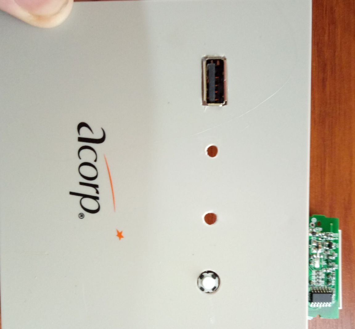
Let's start with the selection of the case for future homemade. I went through a lot of options. I thought to make the case not standard, but, for example, from plywood or wood. But trying to cut a piece of plywood in the room, I got a bunch of dust and debris. The idea of a wooden case also seemed to me difficult to implement in an apartment environment. Then a square plastic box without one wall caught my eye. In my opinion, it used to be a card reader from a desktop computer. On one side of the box was the Acorp logo.
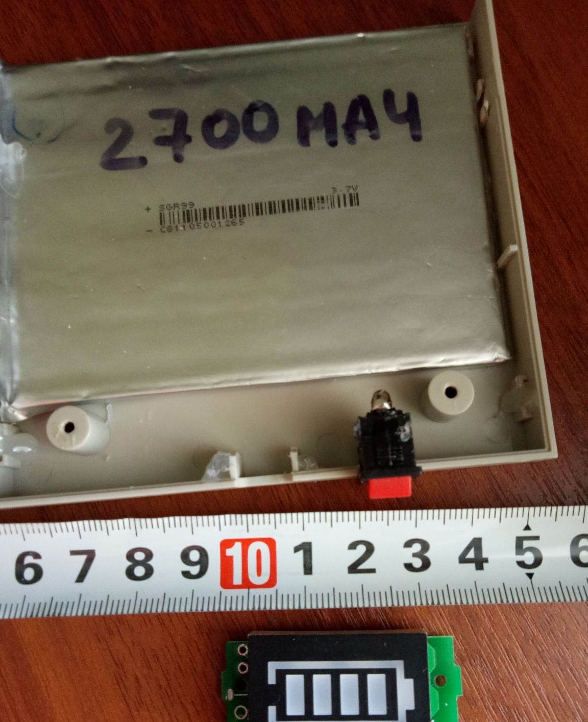
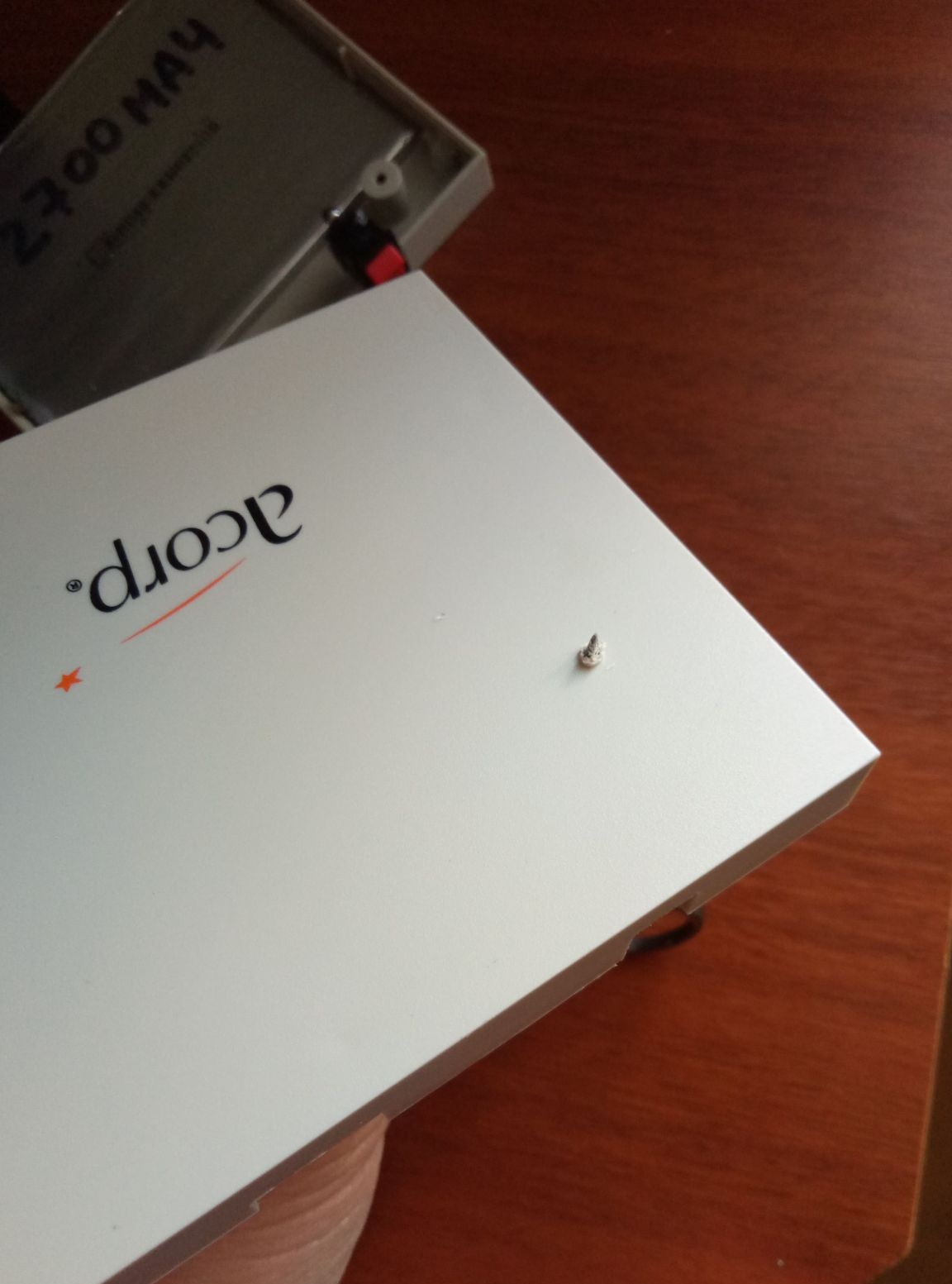
I decided on the case. In size, it turned out to be quite roomy. 3 banks of 18650 li-ion from the battery of an old laptop can easily fit inside. But after their charge, it turned out that for a long time working in a laptop, none of the 6 cans I tested had a charge (they self-discharged). It was decided to use another lithium battery. Became a donor electronic book. The screen did not work for her (it was broken), but I remember that it held a charge for quite some time (about 8 hours of the screen turned on). The capacity declared by the manufacturer is 2700 mah. The dimensions of the battery are decent, but it fits in the newfound case.
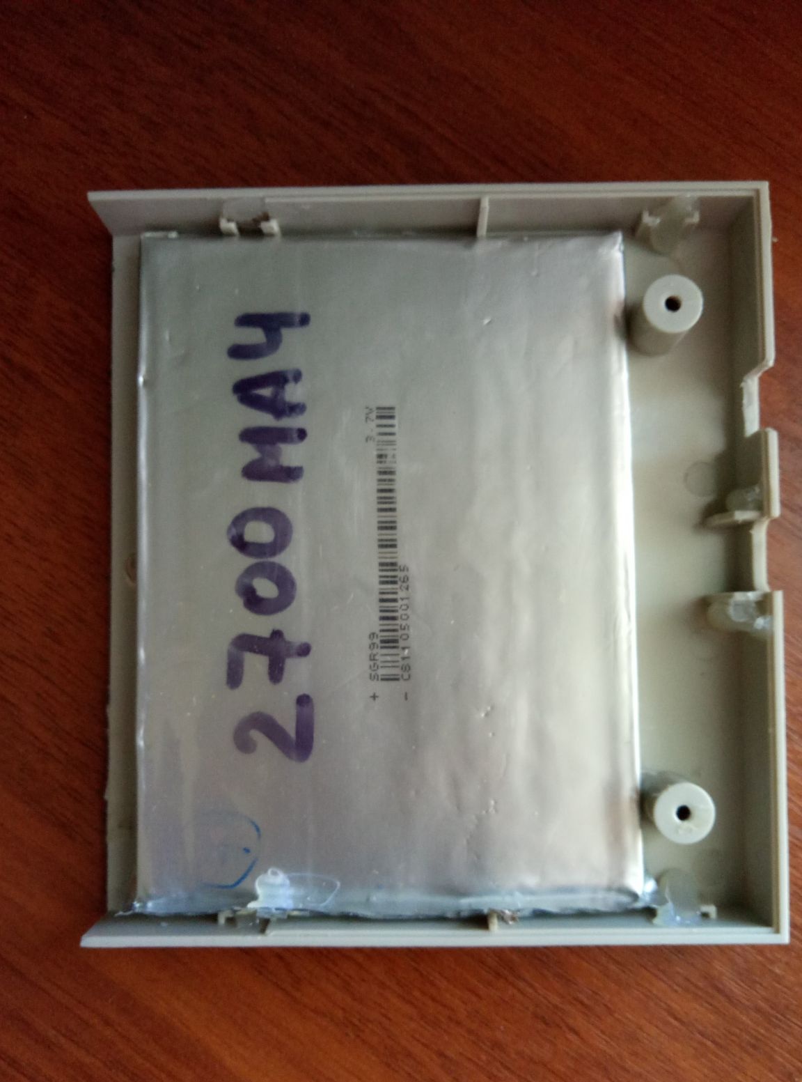
Moreover, the battery is quite thin and I fixed it on one side of the box.
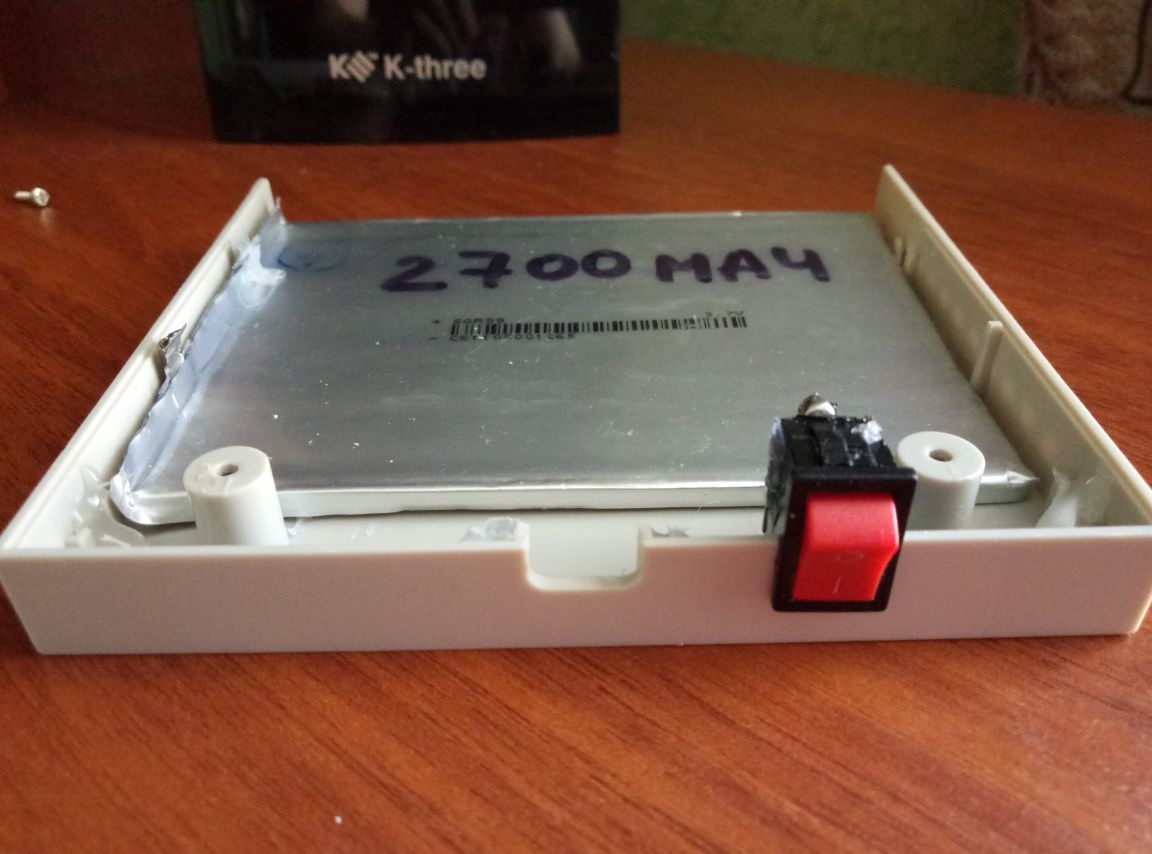
The other half will house the rest of the electronics components.
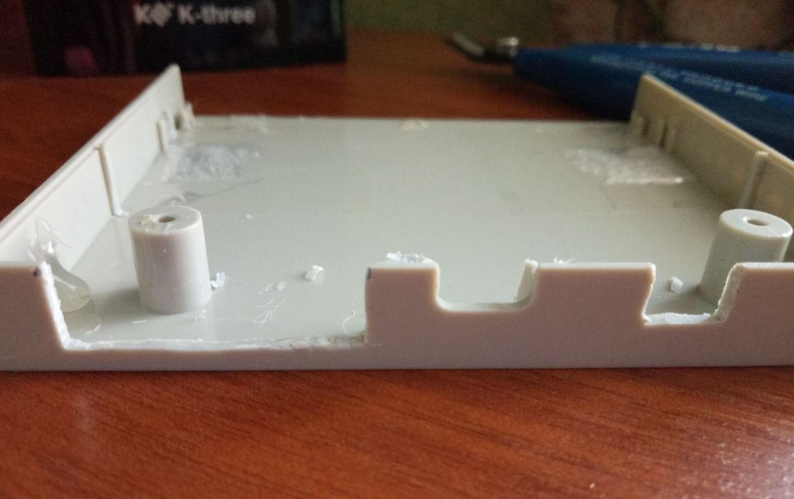
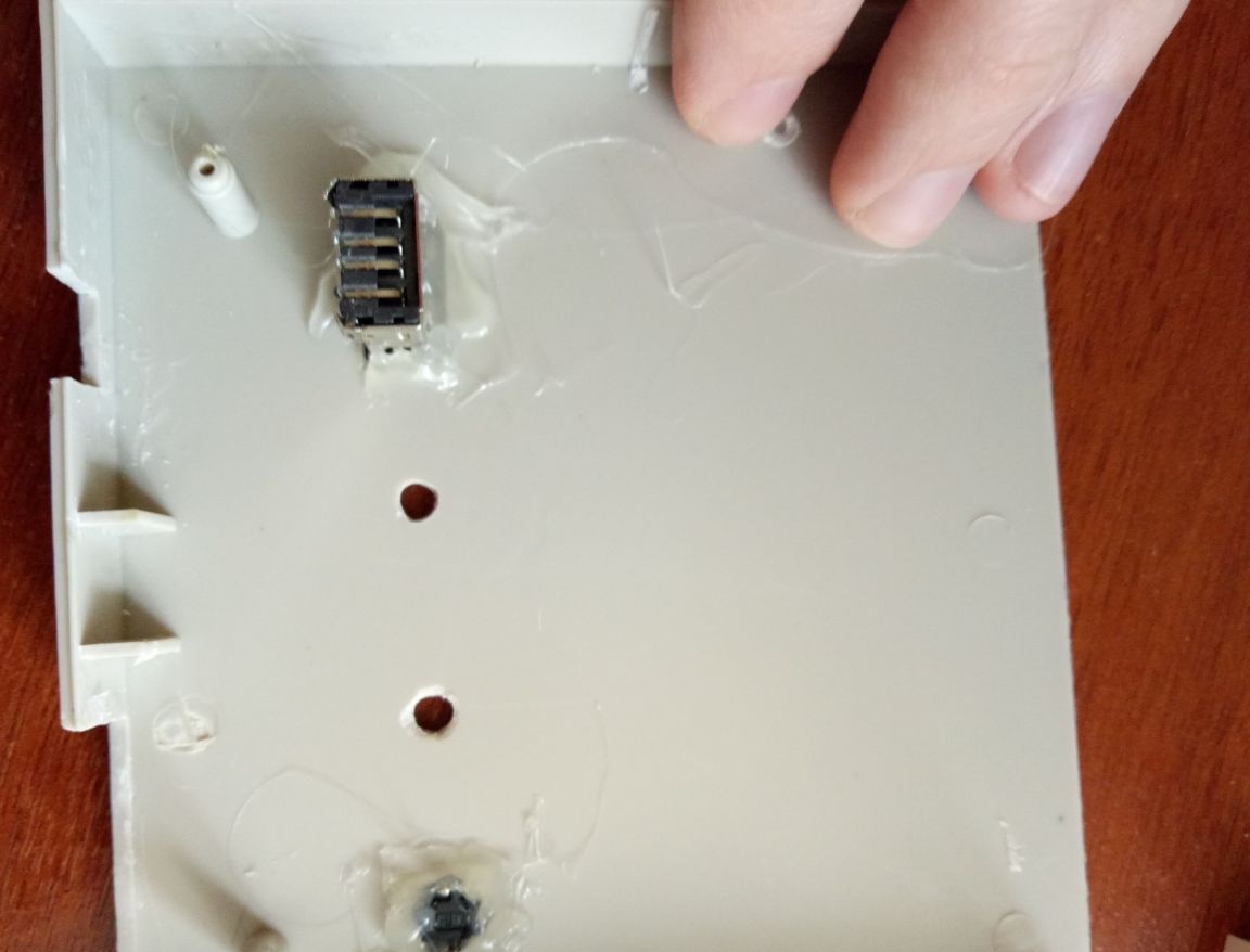
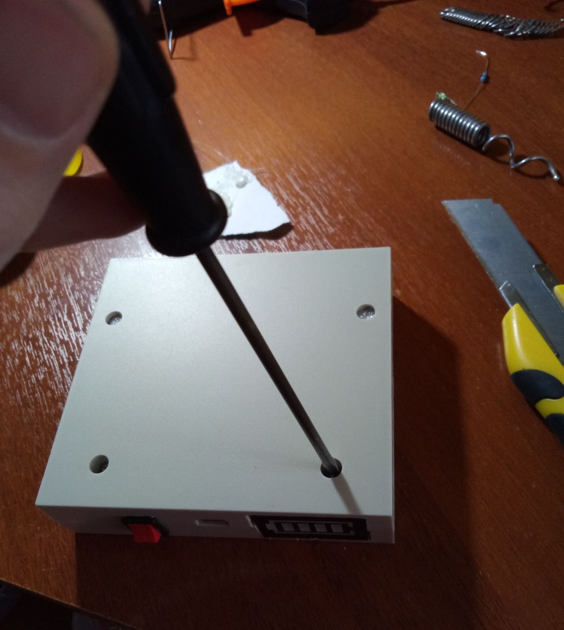
On the side I inserted a micro switch.
There was a notch in the middle and the micro usb connector on the board fit perfectly into it, a charger will be connected through it.
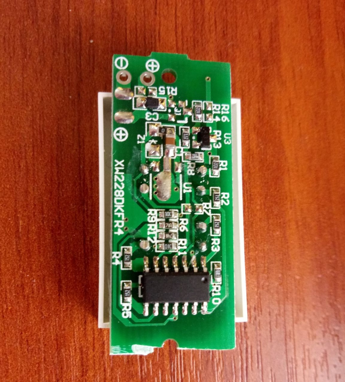
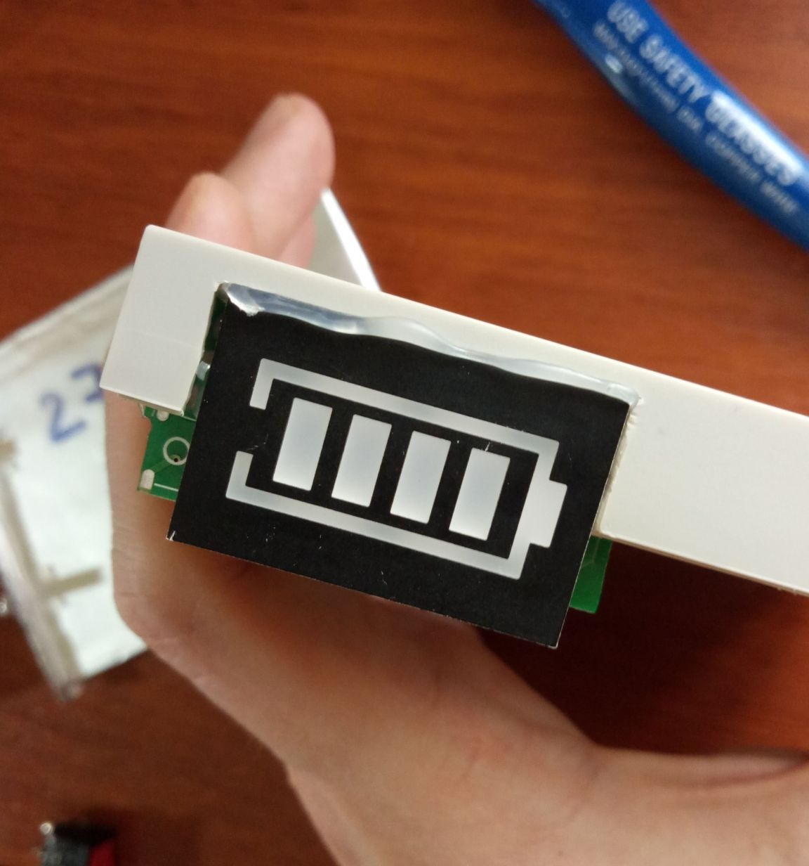
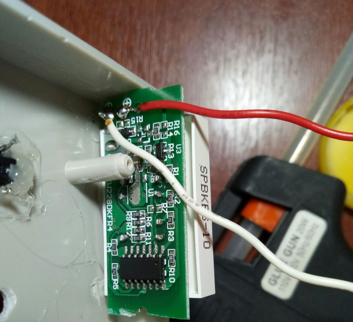
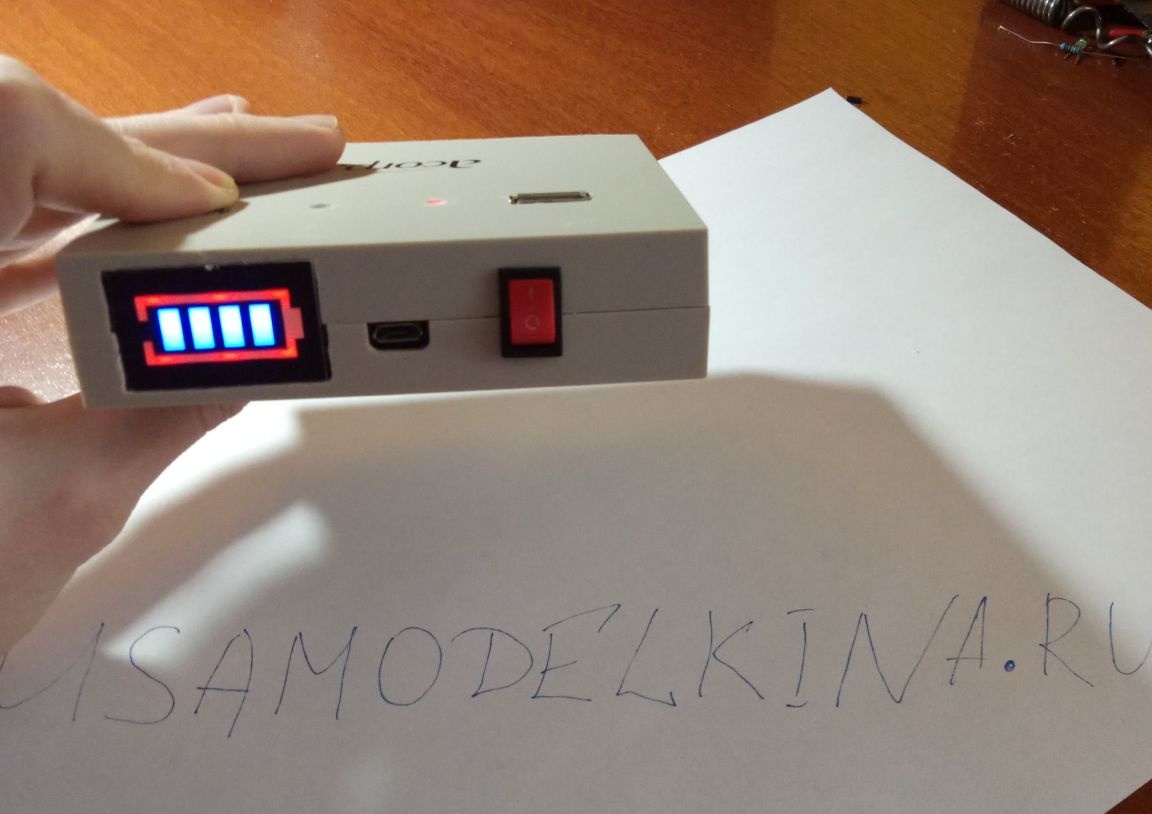
On the left, I decided to insert the battery level indicator module.
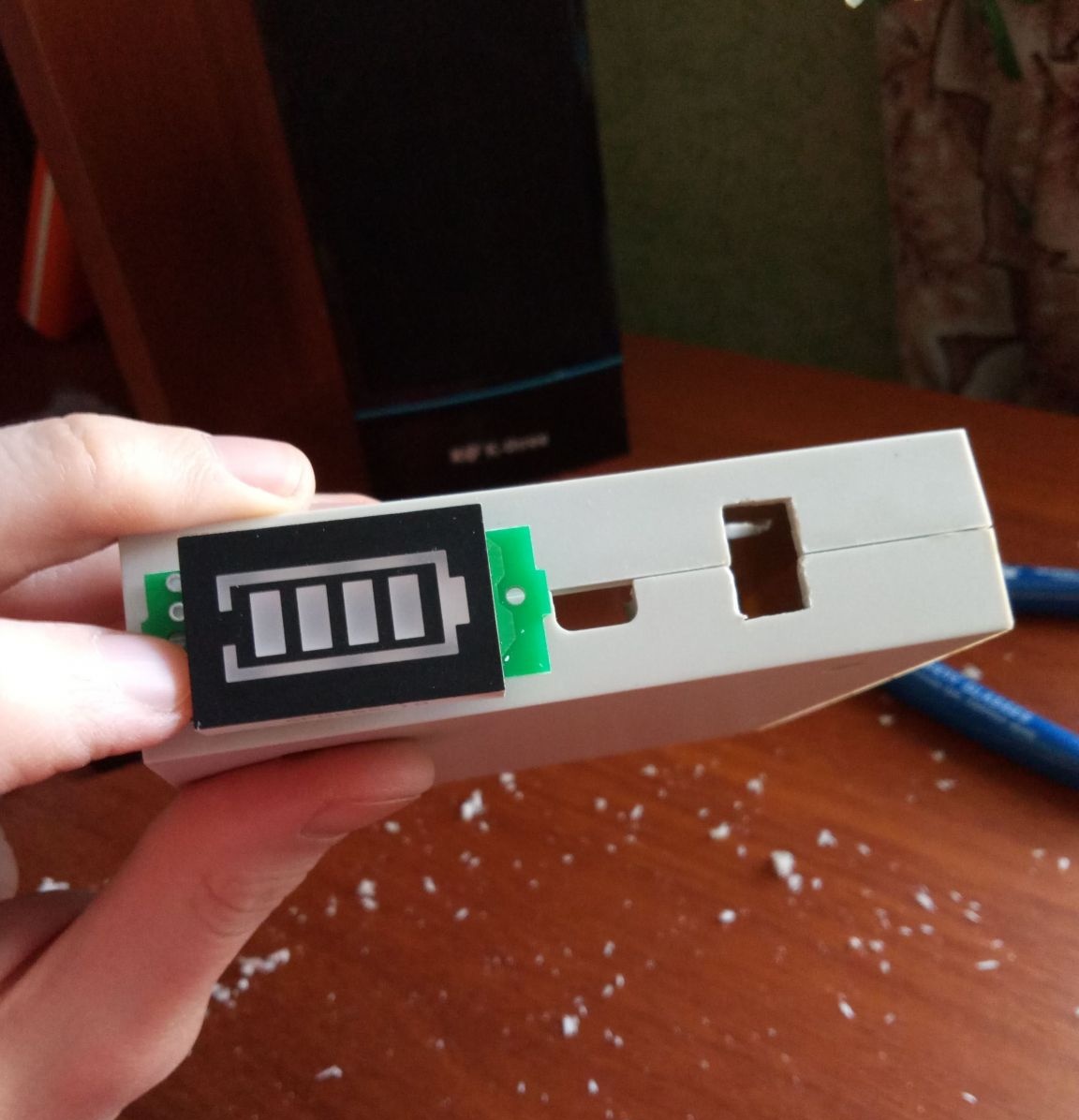
You can’t call the module compact; consider this if you decide to use one in homemade products.
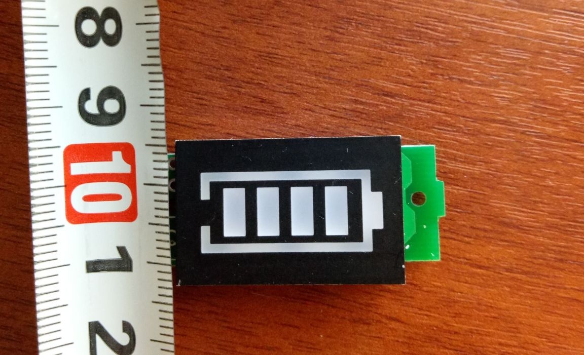
On Ali, there were several varieties of similar indicators for 3.7 Li-ion batteries, this is the largest of them.
Even in such a not-so-small case, I had difficulties with the placement of this module. I had to file a little board.
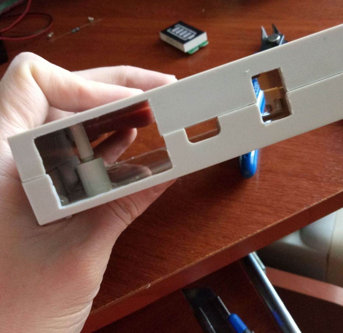
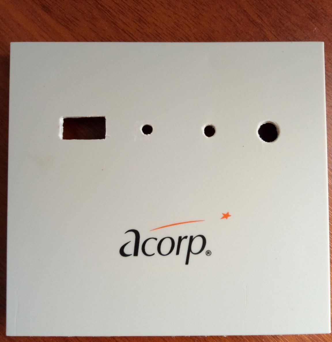
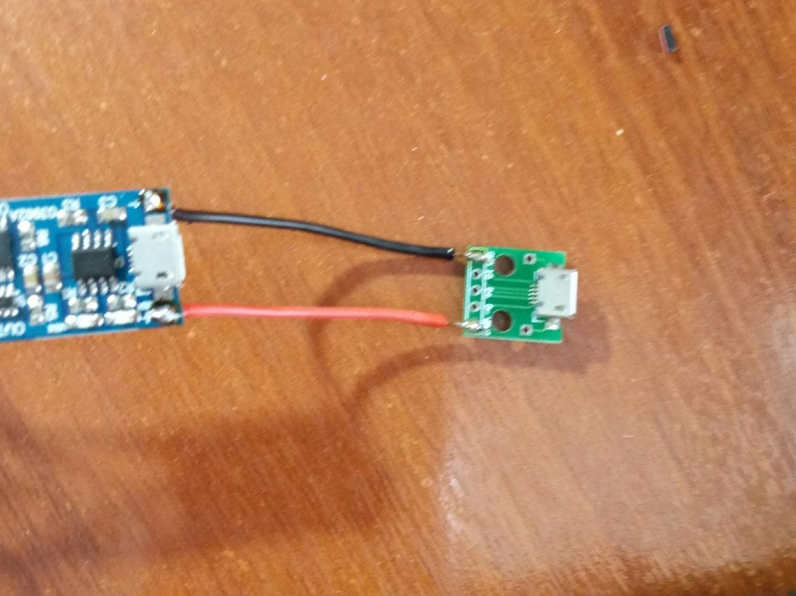
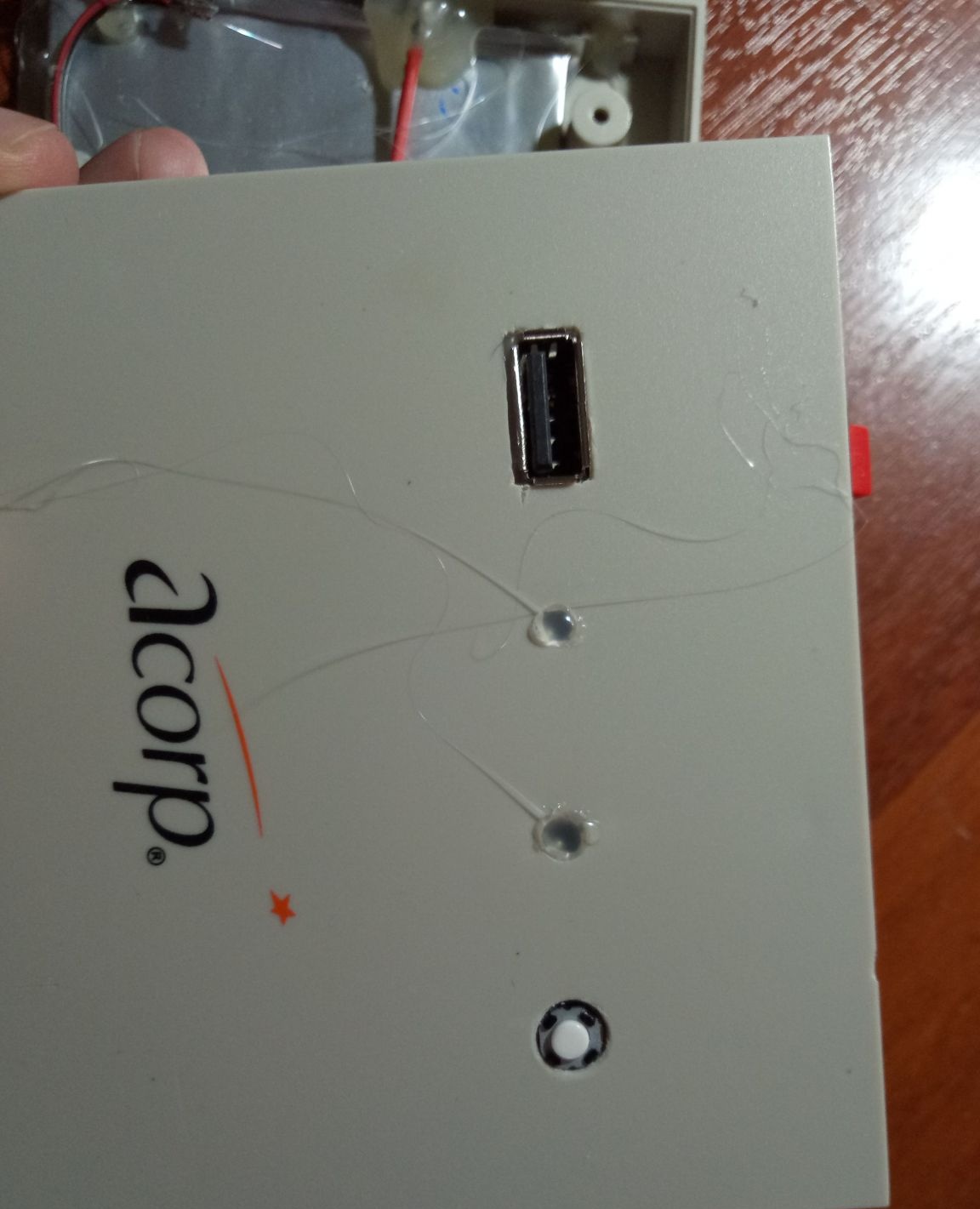
Next, I outlined the location of the boards (charge / discharge, dc-dc boost converter) and usb port. First cut a hole for the usb connector. Although the dc-dc converter board has its own usb port, it is somehow soldered in a crooked manner and the length of the board did not fit if it was placed upside down in the case with the connector. Therefore, I used a separate usb connector.

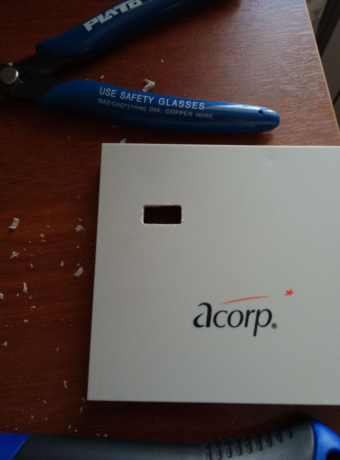
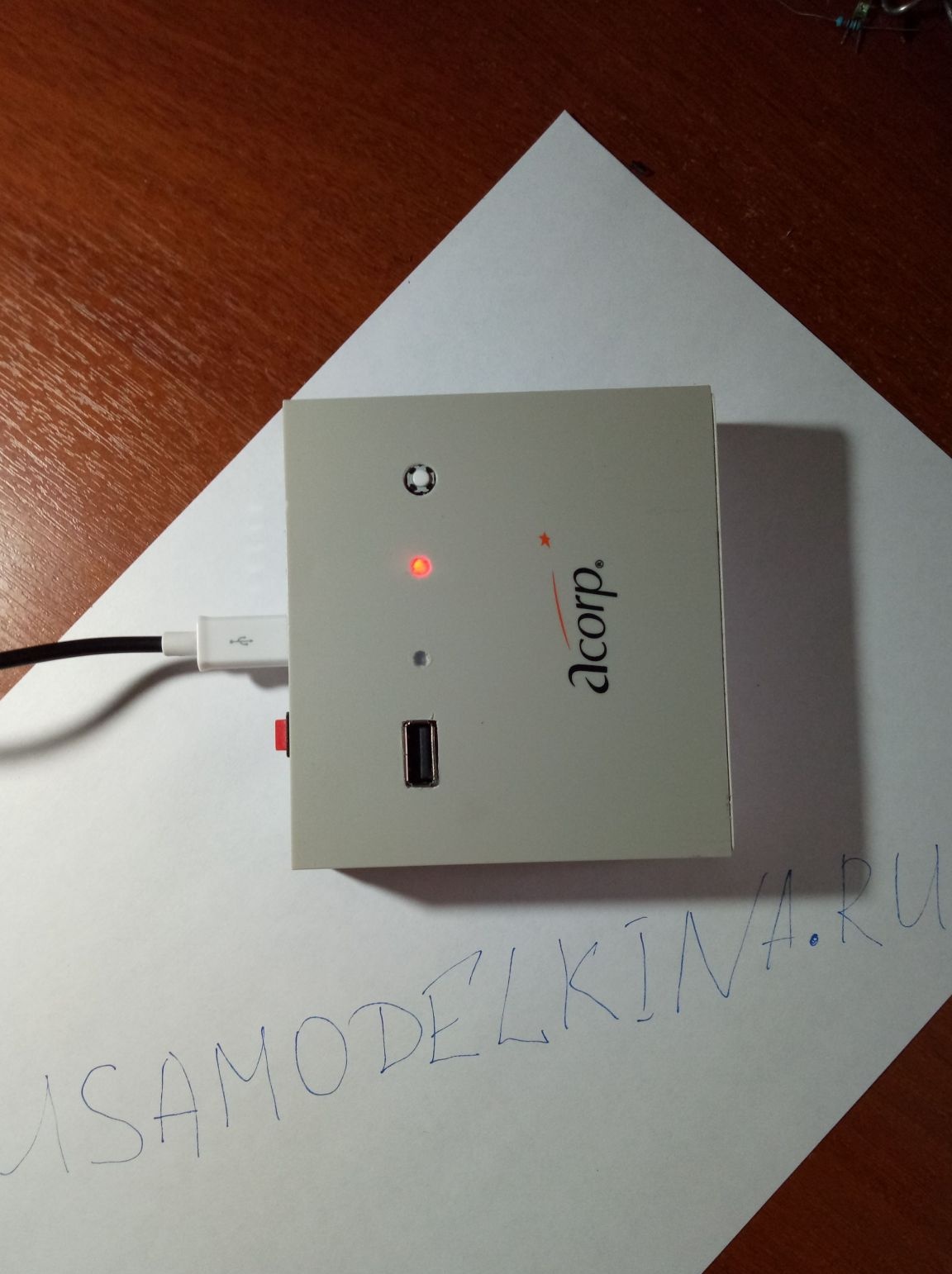
On the boards of the charge controller and dc-dc converter there is an LED indication. It was not visible through the body, so I made 2 small round holes in the body. I made another hole of a larger diameter under the button to turn on the charge level indication.
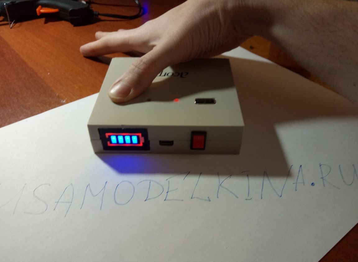
Then he put the usb port in a pre-prepared hole and fixed it with hot glue. In the same way, I installed and fixed a button with a glue gun, which will include an indication of the level of the remaining charge of the bank.
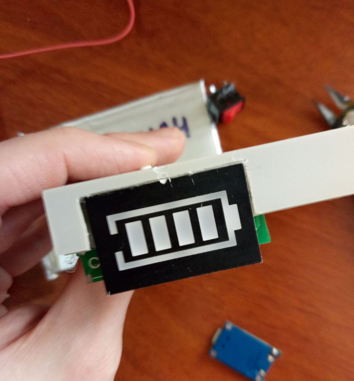
All the same hot glue, but already on the side panel, the indicator module of the remaining charge is fixed.
Then with a knife he removed the excess of hardened glue.
This is followed by soldering. We prepare soldering accessories (rosin / flux, solder).
While the soldering iron is warming up, measure and cut off the wires of the required length. I used a copper conductor with a sufficiently large cross section, since the battery charge current is about 1 ampere. The discharge current in this case will not be large. The dc-dc converter, according to a Chinese seller, can output current up to 0.6 A at the same time, while maintaining a constant voltage of 5 volts. Practice has shown that the real maximum performance of this voltage converter is 0.5 A, while the output voltage drops to 4.2-4.4 volts and the whole circuit heats up significantly. At lower loads it works stably. At the beginning of the article, I spoke in detail for what purposes I am collecting this device, so in my case such a dc-dc converter will work fine. If you want the gadget to be able to charge gadgets, such as phones, smartphones, watches, etc., use another boost converter, for example, mt3608. According to the seller, he can give a current of up to 2A, in addition, the Mt3608 has the ability to adjust the voltage.
Then it is necessary to strip the wires from insulation and tin.
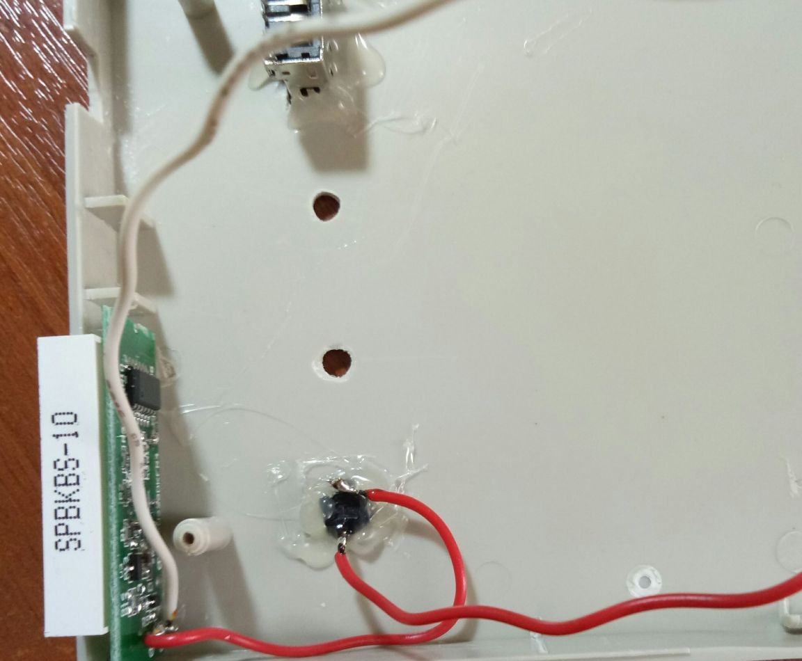
First I soldered the wires to the terminals of the battery.
He filled the joints with hot glue for reliability, so that during further manipulations everything remains in its place.
Then he decided to solder the wires to the charge indication module.It was not very convenient, since I already mounted the module on the side panel of the case and solidly poured hot glue.
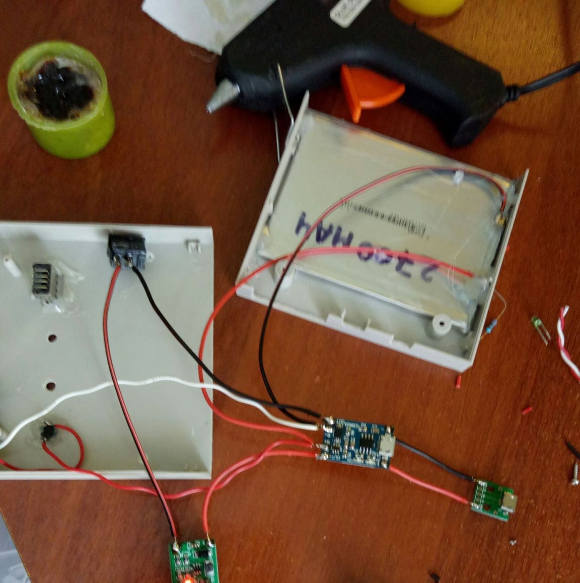
Next, the negative wire (white) was soldered to the battery minus (on the charge controller board), and the red (plus) to the gap through the button was soldered to the battery plus (also on the controller board).
The out + charge controller board output is connected to the in + dc-dc controller input of the in + controller. The out- negative output is connected to the negative input of the in + boost converter via a micro switch. In the following photos, this process is more clear and detailed.
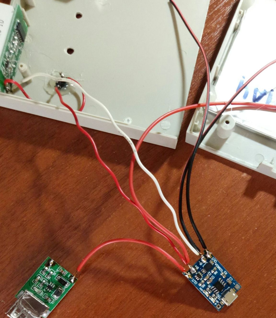
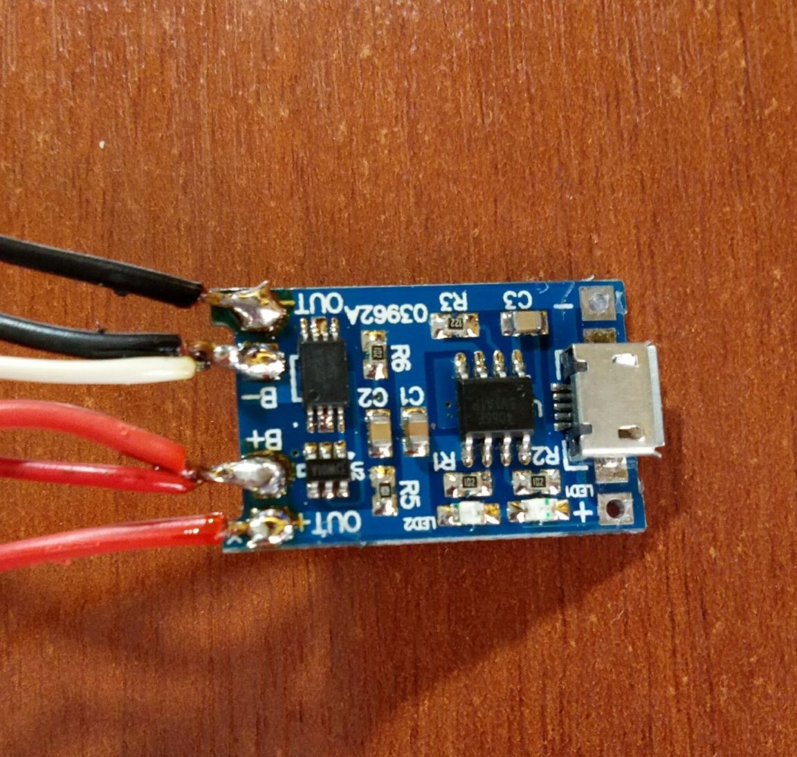
I also soldered 2 wires by connecting the micro usb input and the charging controller circuit.
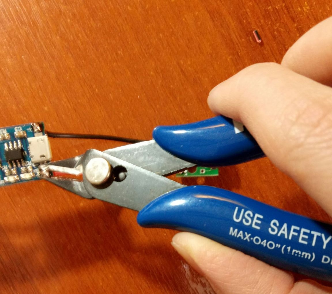
Superfluous deleted.
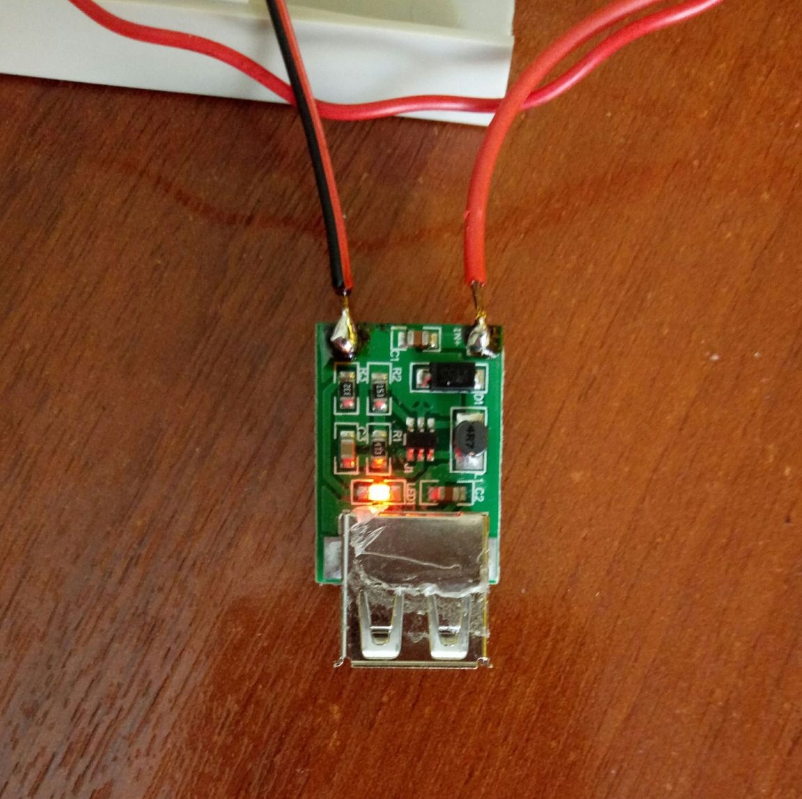
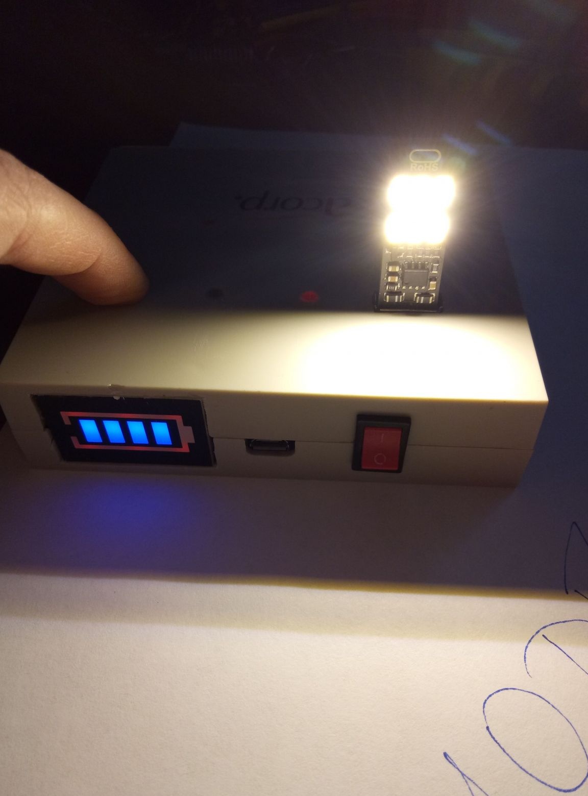
Verification Everything works, the indicator glows red, the circuit is assembled correctly.
I placed the components of the circuit on the inside of the case so that the LED indicators were visible in the specially prepared round holes in the plastic and fixed everything with glue using a thermo gun.
Holes filled with glue. It is transparent and through it the light of the indicators scattering will be perfectly visible.
Then when the glue has set, the excess can be removed.
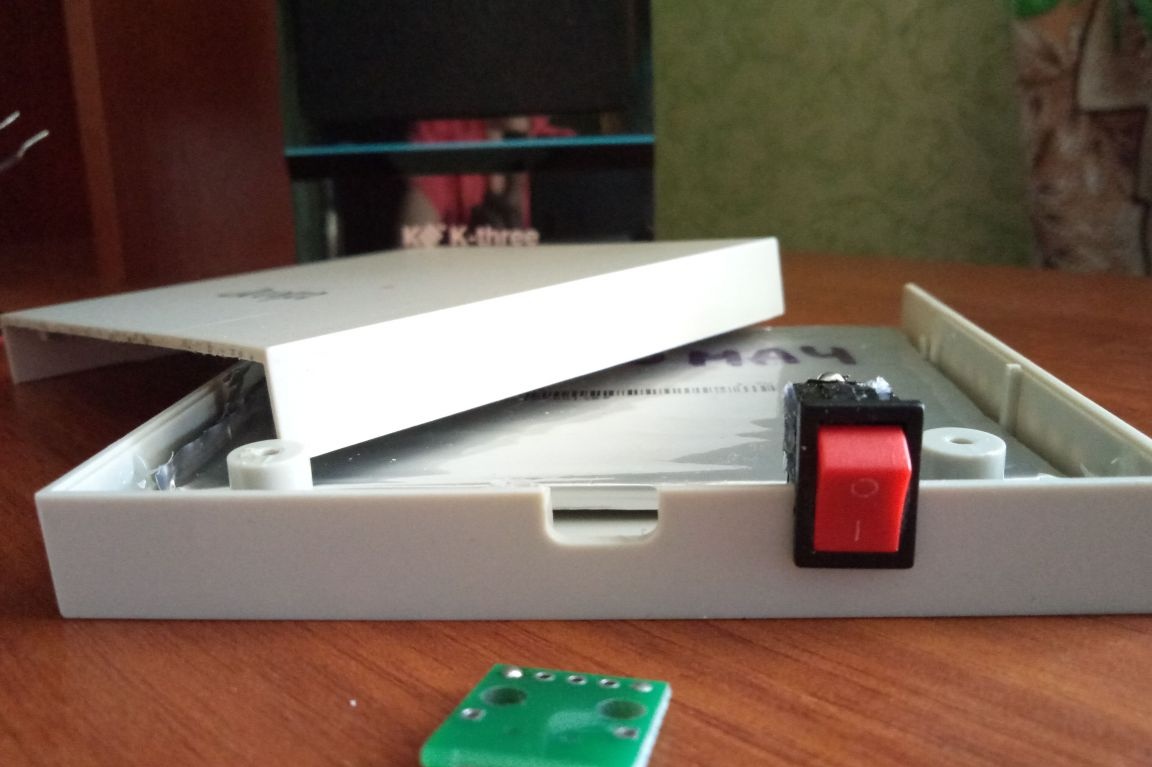
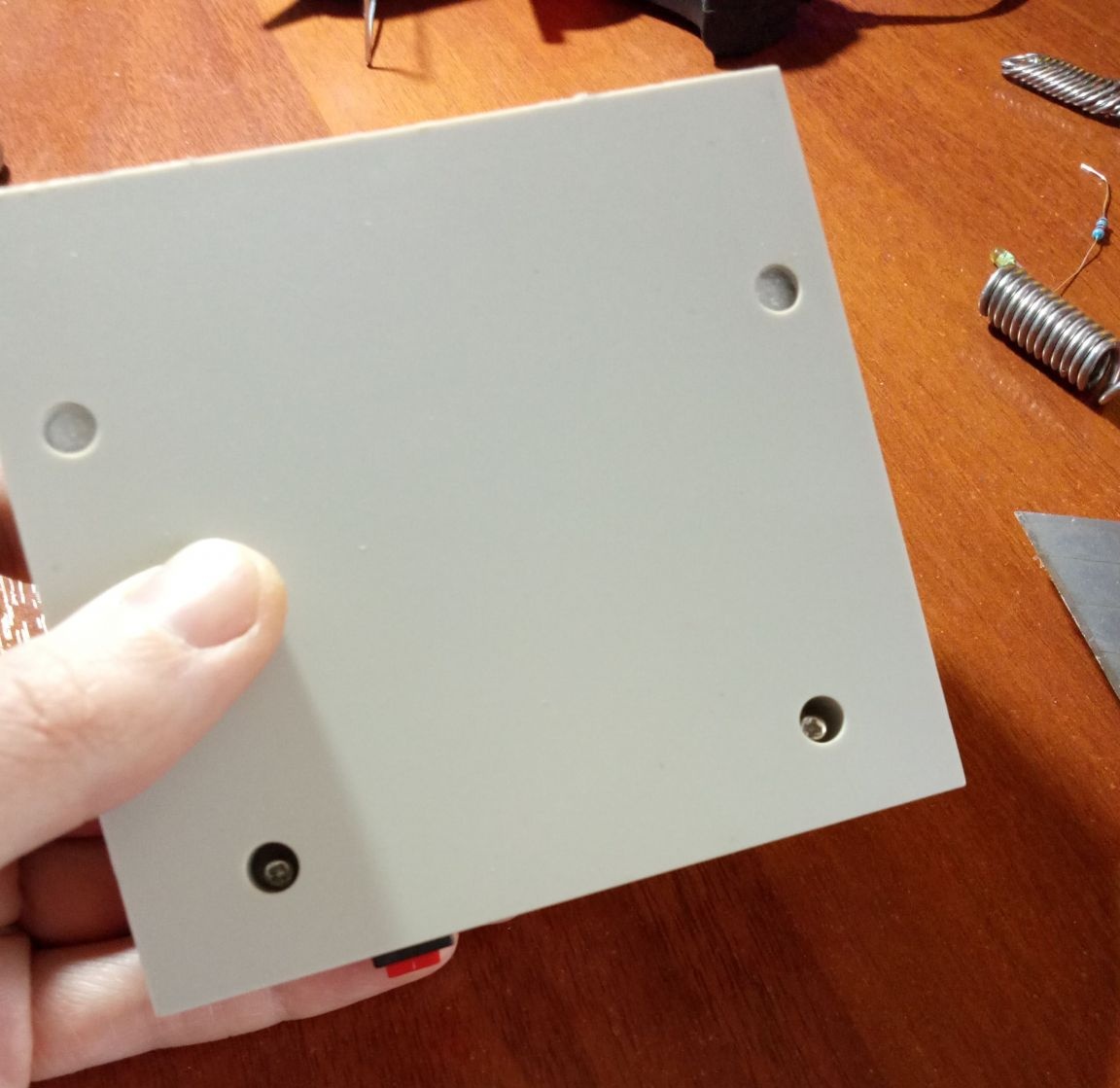
The final stage. I close the case using a screwdriver and a couple of screws.
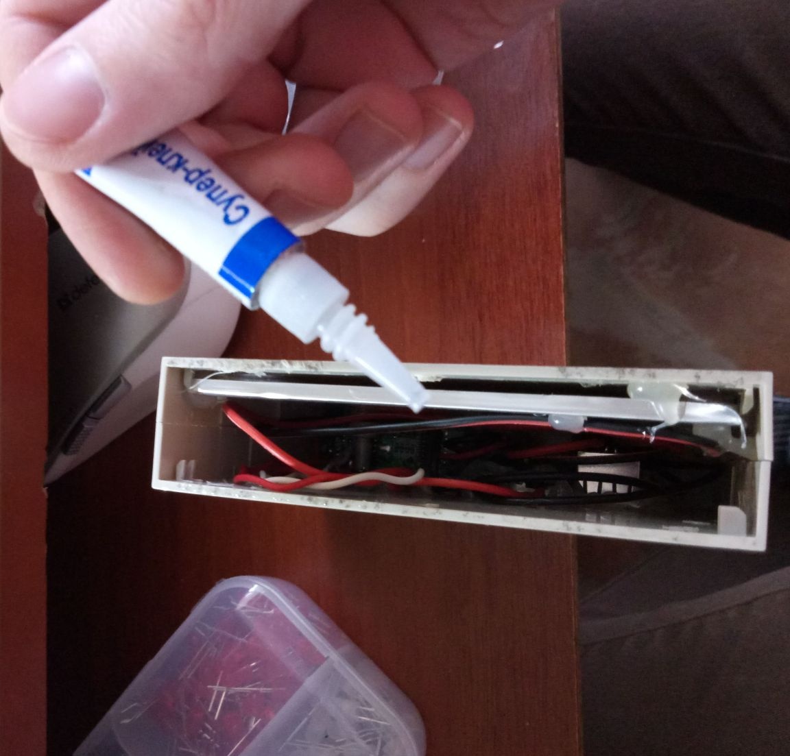
A quick-drying super glue was applied to the open wall of the box around the perimeter. I cut a suitable piece from thin plastic and glued it.

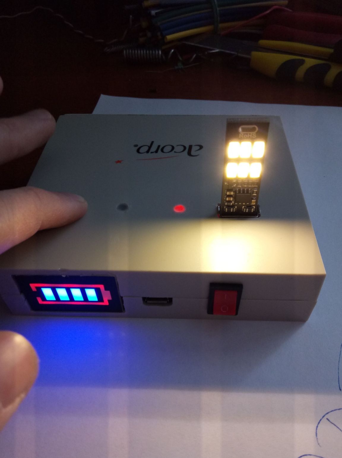
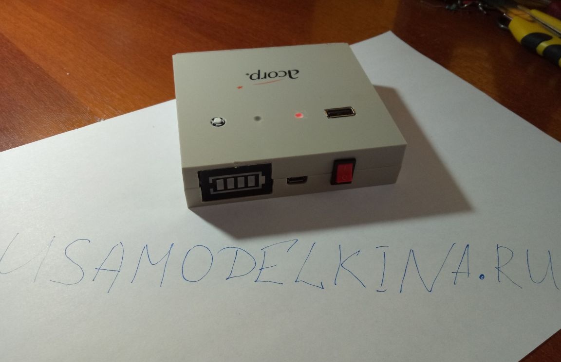
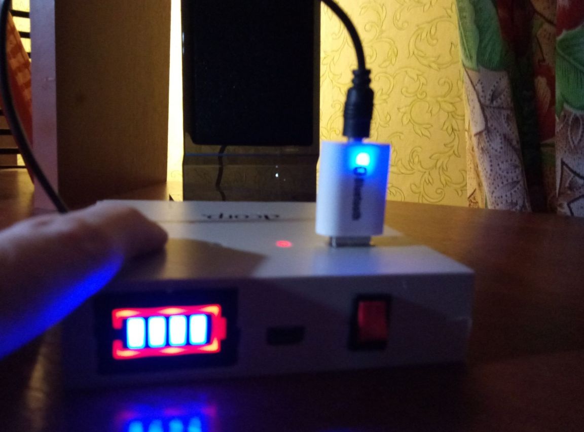
Here's what happened:
And actually with the culprit of this creation - a bluetooth adapter.
Thanks! See you soon!