

When used in the workshop of fire equipment, they feed it in the vast majority of cases with combustible gas or a mixture of them. If metal welding is omitted, then gas from the city gas network or propane is most often used. If it is necessary to obtain a higher temperature, oxygen can be added to the air blast or it completely replaces the air.
Oxygen - gas is very dangerous and not too convenient to use. When used in a workshop, it is necessary to fulfill significantly more stringent safety requirements, oxygen cylinders are designed for a pressure of 150 atm and a standard oxygen cylinder with a capacity of 40 l - it weighs about 75 kg, which does not allow it to be transported and loaded alone. Transportation of oxygen cylinders is subject to special requirements.
There is also a way, relatively simply, to slightly increase the temperature of the burner flame - to use carbonated air (gasoline vapors) to power it. Such combustible gas is prepared in special devices - carburetors and has several advantages compared to gas. This is mainly of course the increased temperature of the torch of the burner, due, inter alia, to the ideal mixing of fuel with an oxidizing agent. Compared to gas, gasoline is safer, since its vapor leaves the tank only when it is purged with air and getting it into the room in dangerous quantities, in the sense of an explosion, is practically excluded. Measures to prevent the leakage of flame inside the hoses and further into the carburetor are somewhat simpler than when mixing oxygen into the air blast - flame arresters are quite reliable in the form of a small cavity behind the burner or inside it, stuffed with a copper "muddle". The pleasant moments include the location of the adjusting valves - they are all (two) located on the carburetor, and not on the hot burner, which greatly simplifies their life. It should also be noted that the delivery of liquid fuel is easier than gas in cylinders, which is a significant advantage in the case of a remote workshop location.
However, now, glassblowers rarely use gasoline as fuel, preferring gas.These types of burners are popular in prosthetics and jewelry and are quite widespread there. Used for brazing and smelting a small amount of metals - silver or gold. These burners are manual, of various, but relatively low power. The carburetor is a metal vessel with soldered nozzles. One of which, reaches the bottom and is equipped with a different type of spray. Air is supplied to it from a small compressor, it is bubbled through a layer of gasoline poured into the container and fed through a short pipe to the burner.
A diagram of a carburetor adapted for use in a glass-blowing workshop is shown in the figure.
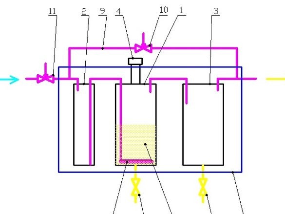
The carburetor is designed for stationary use with a tabletop glass blower. The device also has some additional conveniences - to increase safety during use and has a heating tank with gasoline (not shown in the diagram), which allows you to evaporate from it and burn heavier fractions. A carburetor of this type is described in [1].
The carburetor consists of three metal vessels 1,2,3. The main tank 1 is a bubbler, has a neck with a sealed cap 4 on the lid, designed to fill the tank with gas 5. A copper tube is soldered into the bubbler tank, reaching the bottom of the vessel and ending with an air atomizer 6. Air passing through many small holes of the atomizer is bubbled through the thickness of gasoline and saturated with its pairs. A discharge tube is also soldered into the cap of the bubbler tank to discharge air with gasoline vapors. At the bottom of the tank there is a drain cock 7, for draining heavy residues of fuel, water, possible debris.
Tank 2, serves as a trap in case of a sudden interruption in the air supply to the main tank and has half the volume than half the tanks 1,2. In this case, gasoline, due to the residual pressure of the air mixture in the tank 1, will rush into the tank 2 and remain in it. When resuming air supply, he will squeeze gasoline from tank 2 into tank 1.
The buffer tank 3 has the same dimensions as tank 1. It has two sealed short tubes in the lid. One of them delivers the combustible mixture from the tank 1, according to the second, the mixture goes to the burner. Tank 3 serves as a buffer for trapping drops, partial condensation and collecting gasoline if its evaporation in tank 1 is too rapid. This happens when filling in fresh gasoline. In the lower part of the tank there is a drain valve 8 for draining condensed gasoline. This gasoline is of quite good quality and can be returned to tank 1.
Between the inlet and outlet of the carburetor, a bypass tube 9 with a needle valve 10 is soldered, which allows smoothly regulating the concentration of fuel vapor in the combustible mixture.
At the inlet of the carburetor there is a needle valve 11 for regulating the air supply to the device.
An electric heating is installed on the main tank 1 to improve the volatility of gasoline when its most volatile fractions are carried away by an air current. Electric heating is designed to reach a temperature of 120 ... 150 ° C and captures the tank to a height of 2/3 from its bottom. Electric heating allows you to use the fuel more deeply and makes the system more economical.
Tanks are connected by rigid copper pipes, placed in box 12 and filled with dry sand. In this case, the cranes 7.8, 10, 11 and the neck of the gasoline 4 are released outside, as well as the nozzle for connecting to the burner.
Filling with sand, in addition to increasing the safety of the device, increases its heat capacity and prevents sudden changes in temperature in the device (gasoline cools during evaporation), leading to fluctuations in fuel evaporation and an unstable torch on the burner. All this makes working on a burner with such a carburetor more comfortable.
So, let's get down to manufacturing. It’s worth starting with the simplest part - the gas trap vessels.
For the conversion into the vessels of the carburetor installation, two small electric samovars, lying in the attic, perfectly approached. 4l capacity TENY, plug valves, made of brass. For a trap vessel, I asked a neighbor of the same type for a kettle, without a lid and with a dropped nose - in the garage he was lying around.
What was used in the work.
Tools, equipment.
All connections were made by soldering - you need a small gas burner. Set of bench tools. Medium size abrasive sanding pad for sanding soldering spots. For an accurate cut of copper tubes, it is convenient to use an end pendulum saw, or a miter box with a hacksaw will do.
Materials
In addition to the kettle itself, copper and brass trimmings, thin steel wire for technological fasteners, and 15 mm diameter copper tubes were used. Tin-copper solder No. 3, flux to it. Brush.
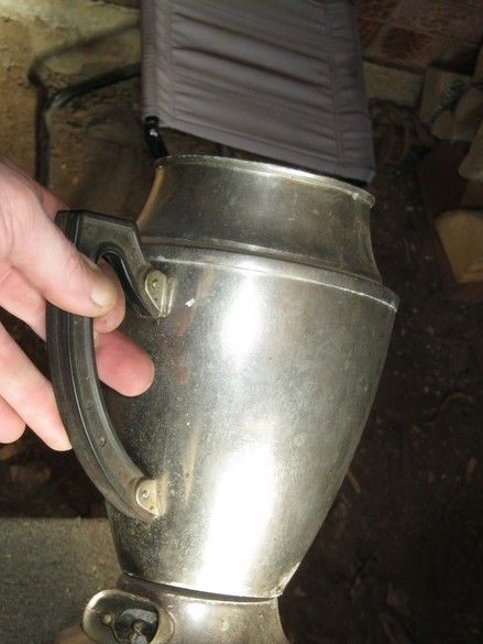
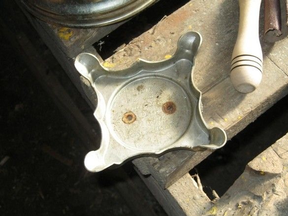
First of all, the kettle was dismantled - popshik with penetrating grease and having waited until it slightly dissipated, screwed the handle and the heater, the latter still broke inside and had to tinker.
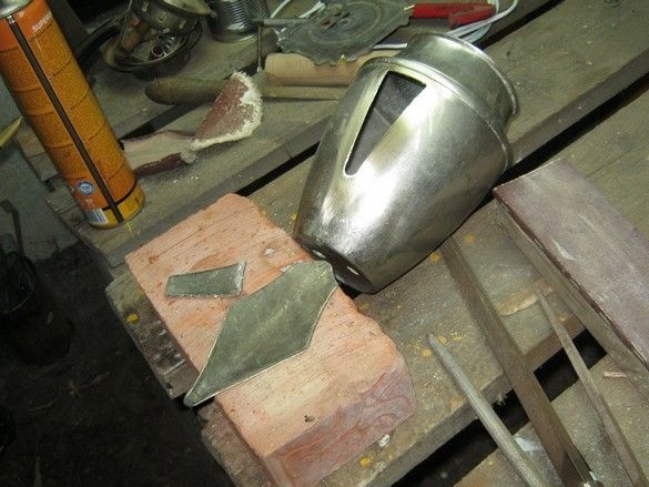
To seal the hole in the body from the nozzle, the nozzle itself, issued by the former owner in addition, was useful. It was soldered and annealed for softness, then it was leveled on the anvil and cleaned - it turned out to be an excellent piece of sheet brass, even somewhat larger than necessary. He put it on the hole, slightly bent over the shape of the case, so that it fit snugly and outlined the silhouette of the hole from the inside with a felt-tip pen.
After cutting with a “grinder”, he sawed off a bit and dulled the sharp edges with a file. I cleaned both surfaces before soldering, applied a soldering flux and fixed it with a thin steel wire. You can solder.
After soldering, he removed the wire, washed off the rest of the flux with water using a paint brush.
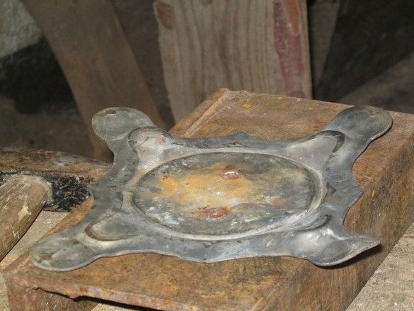
Similarly, he sealed the holes from the heater in the bottom. I picked up a piece of copper of suitable thickness in the scraps.
My samovars from which the remaining parts of the carburetor will be made, slightly higher than our teapot, and in order not to make too long tubes of expensive copper, I made a small stand a glass of vulgar galvanized, fortunately, it is perfectly soldered by the same means. The cup itself rolled up and tapped with a mallet on a wooden disc, tied with wire from above. I pulled out a blank from one edge so that it would not burn during soldering, cleaned it up, soldered at three points.
Now the pipes. The tubes that were used in this design are 15mm copper, from the copper water supply. It would be more correct to use regular angles-couplings-adapters, this would greatly simplify and strengthen the design. But it all hurt far from me and a decision was made to get by with what is - tubes of several diameters and several types of connecting parts were available, remaining from a different design.
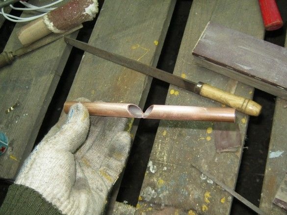
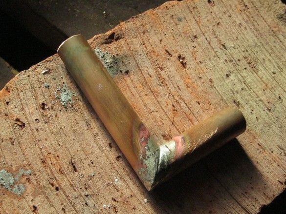
When bending even an annealed tube of such a diameter, it is difficult to achieve an acceptable quality of bending. It was decided to make a "corner" of 90 degrees by soldering. The ends of the tube blanks were trimmed at the end saw. Neatly, with glasses and headphones, with a small pitch.
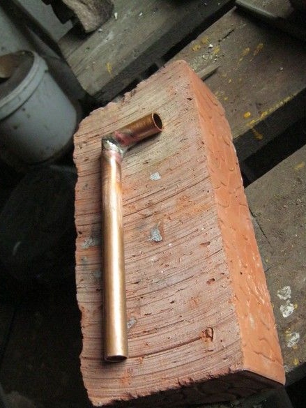
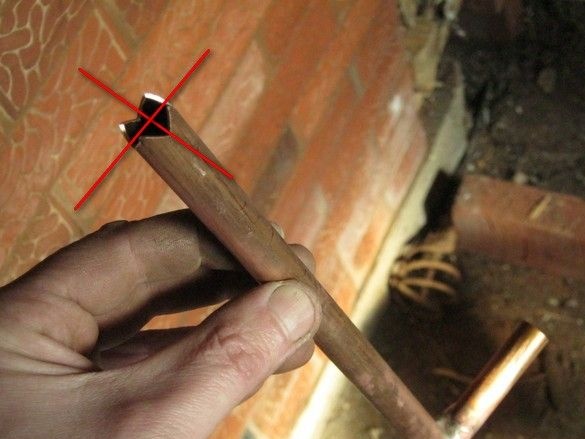
The tube reaching almost to the bottom should not overlap when touching the bottom, but also be very close to it so that the gasoline caught is pumped back as much as possible. To set this distance to the blind, I made such distance elements, holding the tube in a vice and sawing the grooves with the corner of a small square file.
The regular lid of the teapot that I got was, unfortunately, absent, I had to invent my own. A large piece of thick brass was very sorry and decided to straighten the stand from one of the samovars. To do this, annealed it on the burning coals in the stove.
Evened out but not completely - still annealing.
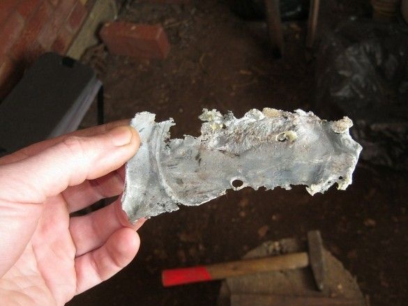
He decided to anneal, as it should, and buried it in well-burning coals. Oh you to me! Everything was gone chef. I had to use the delivery from the second samovar and be careful with annealing.
Cutting out the necessary workpiece from the resulting plate, he drilled and bored holes for pipes with a round file. Thoroughly cleaned it and neck, sealed.
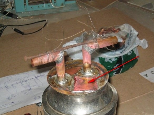
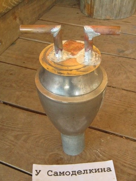
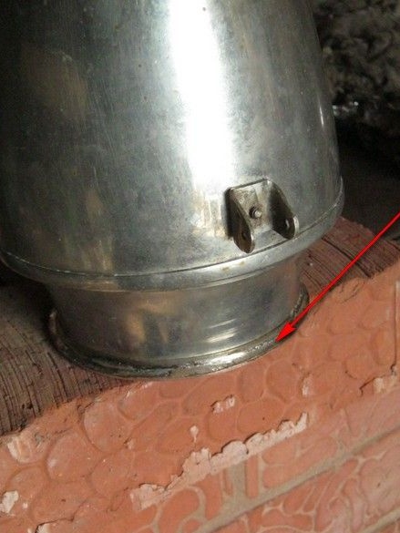
I first soldered a long tube, then, with a pipe, at the same level with it, soldered a short one to fix the pipes during soldering, wrapped a long nail with wire.The arrow shows the patch, which still had to be put in the hole from the electric block of the samovar.
Washed off the flux residues with water. Voila!
Part 2. The bubbler
Literature.
1. Veselovsky S.F. Glassblowing business. 1952
2. Bondarenko Yu.N. Laboratory technology. Production of gas discharge light sources
for laboratory purposes and much more.