

About five years ago, I purchased a Nikon Coolpix L320 camera that runs on four AA batteries. At first I used only alkaline batteries, but they lasted for a couple of dozen shots, and then the camera refused to work, so in order to save money and stable operation, I decided to buy high-quality Ni-Mh batteries Fujitsu 2000 mAh HR-3UTC EX without memory effect with LSD technology (low self-discharge) and high current efficiency, which is ideal for charging the flash.
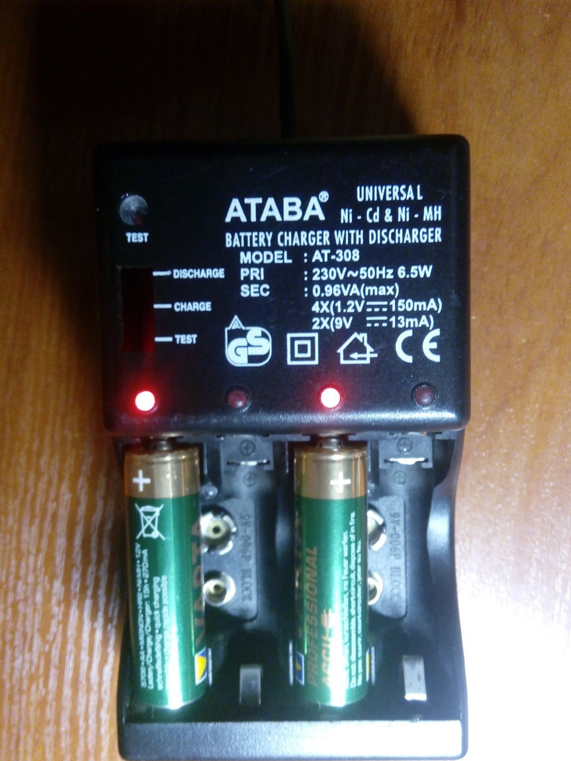
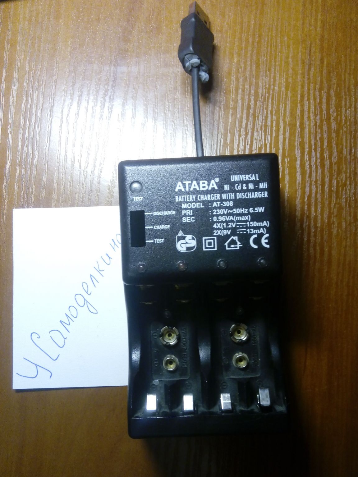
To charge the batteries, I first used the ATABA AT-308 charger, which was bought for a very long time, but the quality of the charger did not suit me.
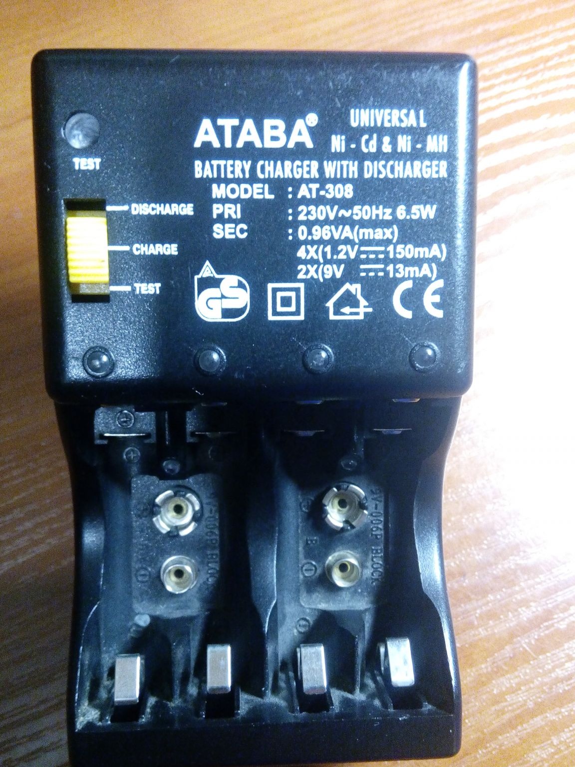
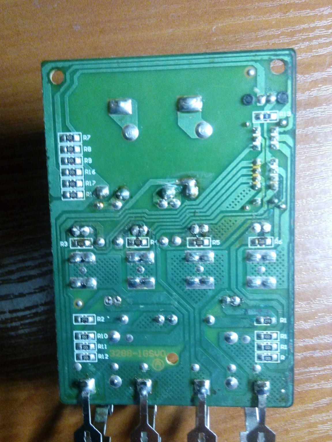
The principle of charging was to limit the charging current from the transformer power source by means of current-limiting resistors, in addition, the declared charge current of 150 mA did not correspond to reality and was much less, the same situation was with charging 6F22 (Krona) the charge current was less than 10 mA.
It was decided to make their own charger in the ATBA AT-308, but with a different circuit diagram, which would include battery charge control and visual control of the end of charge
Materials:
microcircuit LM324;
microcircuit MC34063;
microcircuit TL431 (adjustable precision zener diode);
microcircuit LM317;
KT815 transistor (NPN transistor);
LEDs 5 pcs;
0.5 ohm resistor;
10 ohm 2W resistor;
27 ohm resistor;
resistor 39-51ohm;
180 ohm resistor;
470 ohm resistor;
750 ohm resistor;
1 kΩ resistor
2 kΩ resistor
3 kΩ resistor
8.2 kΩ resistor
10 kΩ resistor
36 kΩ resistor
diode 1N4007;
Schottky diode 1N5819;
throttle;
non-polar capacitor 0.1 uF;
non-polar capacitor 470 pF;
100 μF oxide capacitor;
470 μF oxide capacitor.
Instruments:
soldering iron, solder, flux;
electric drill;
jigsaw;
drill.
Step-by-step instructions for making a charger for Ni-Cd and Ni-Mh batteries
The heart of the charger is the LM324 chip, in the housing of which there are four independent operational amplifiers.
The circuit is designed to charge one battery, so I will assemble the device into four channels on the LM324 chip, while the R5-R6-R7-R8-TL431 chain will be common to all channels. The inverted inputs of the LM324 are combined and connected to R5. The output voltage (on the batteries when charging) is set to 1.46 V using an adjustable precision zener diode TL431 and resistors R6 and R7.
The charge current is set by the resistor R3 and at a value of 5 ohms, it is about 260 mA, which is slightly higher than 0.1C for my case. Decreasing the R3 rating will increase the charge current proportionally. To obtain the required current, I connected in parallel two 10 Ohm resistors (there was no desired rating). Power resistors 2W.
The KT815 transistor can be replaced with a complete foreign analog BD135 or another, having selected according to the characteristics. I got 2 pcs. KT815, KT817 and BD135
The end of battery charge is indicated by an LED. As the charge progresses, the LED will shine more weakly until completely attenuated at the end of the charge. LEDs set superbright 5 mm.
In addition, the ATABA AT-308 charger involved charging 2 pcs of 6F22 batteries (Krona), and since I use one of these to power the multimeter, I decided to create a simple circuit for charging 25-30 mA in parallel.
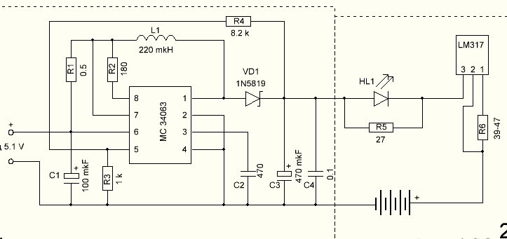
The first part of the circuit is based on the MC34063 chip, which will convert 5V from the power supply, which I will use for my charging, to 10.5-11V. This is the simplest solution in my case, especially with limited space for mounting radio components.
To obtain the required output voltage, it is necessary to select the voltage divider resistors. The network is full of online calculators for this chip, if you do not want to manually recount.
The second part of the circuit is assembled on an integrated linear voltage regulator, and in my case, a current, LM317L with an output current of up to 100 mA. The stabilizer assembled according to this scheme performs the function of stabilizing the current, which is important when charging the battery. The charging current is adjusted by selecting the resistor R6, the calculation of which can be viewed in the datasheet on the chip or calculated on the online calculator. I set 51 Ohms for a charge current of 25 mA. LED HL1 and resistor R5 act as a unit for indicating the charge process.
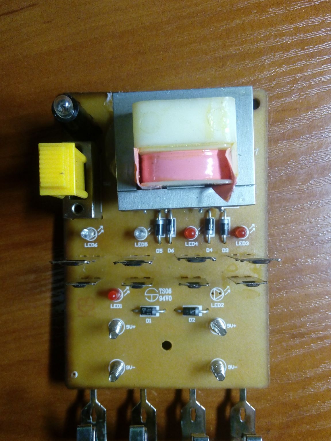
Since the circuit was supposed to fit in the ATBA AT-308 case, it was necessary to lay the circuit board taking into account the "features" of the case, namely, the battery pads, mounting holes and indicator LEDs should remain in their places.
He drew the circuit board in the program SprintLayout_6.0.
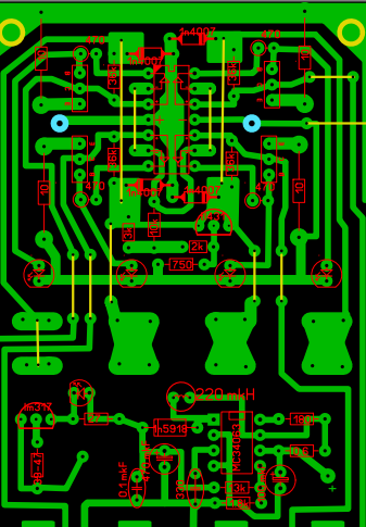
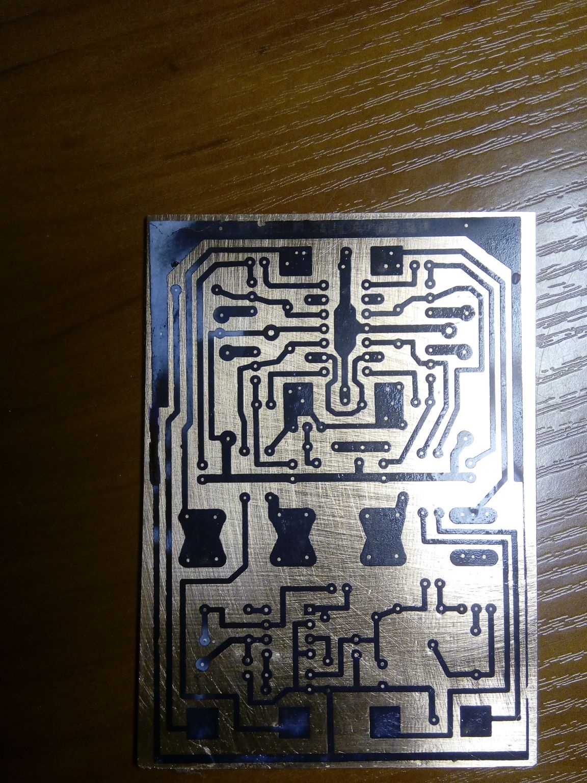
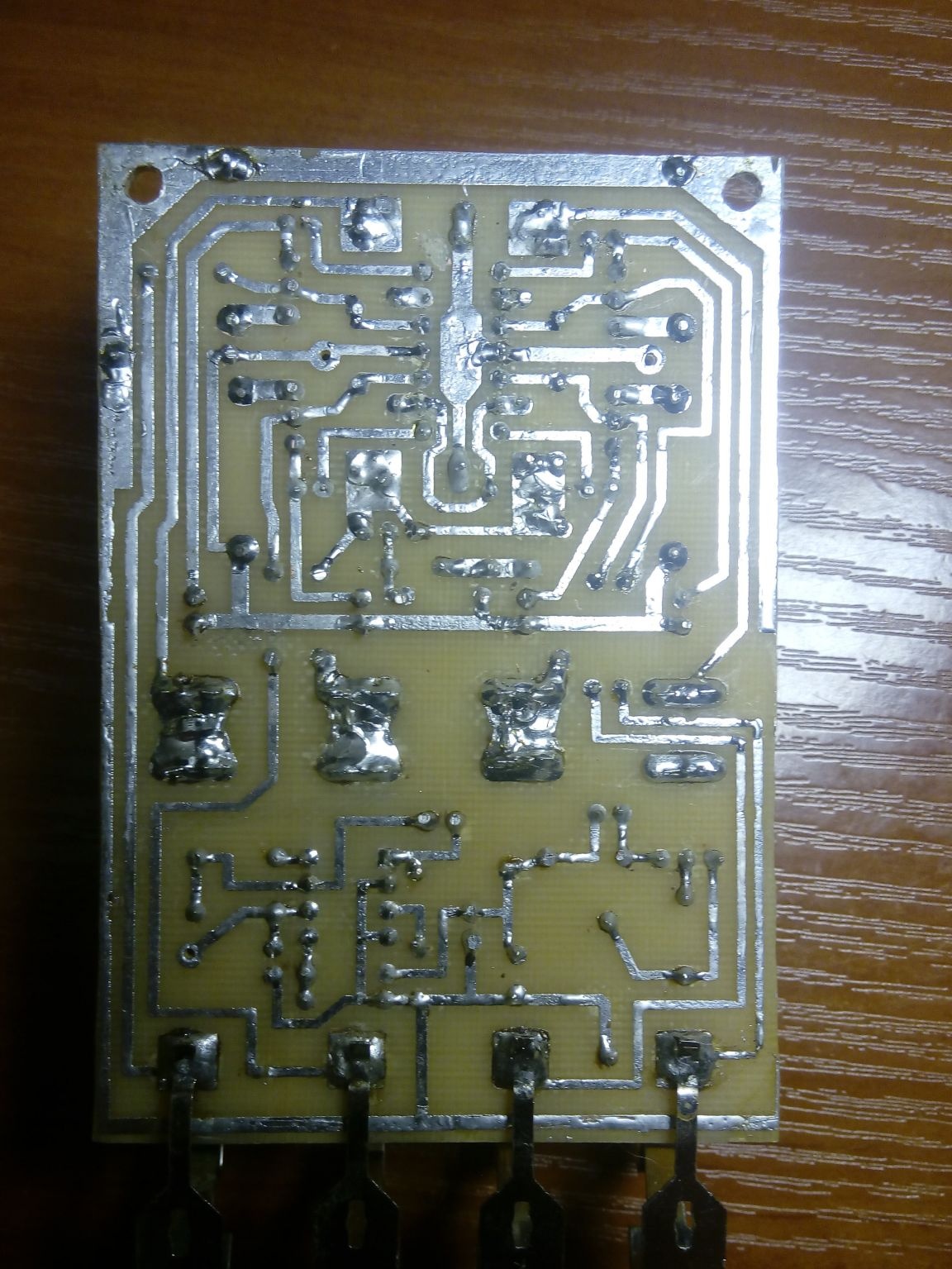
He transferred the image to the foil textolite according to the LUT method, etched, drilled holes on the printed circuit board and tinned printed current paths with tin-lead solder. Well, here, as usual, there is nothing to tell.
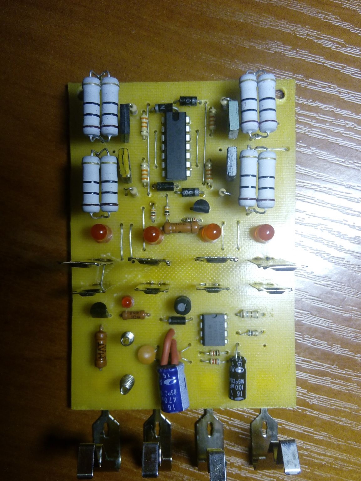
I soldered the radio components on the printed circuit board in accordance with the circuit diagram. R3 resistors raised above the printed circuit board to improve thermal conditions.
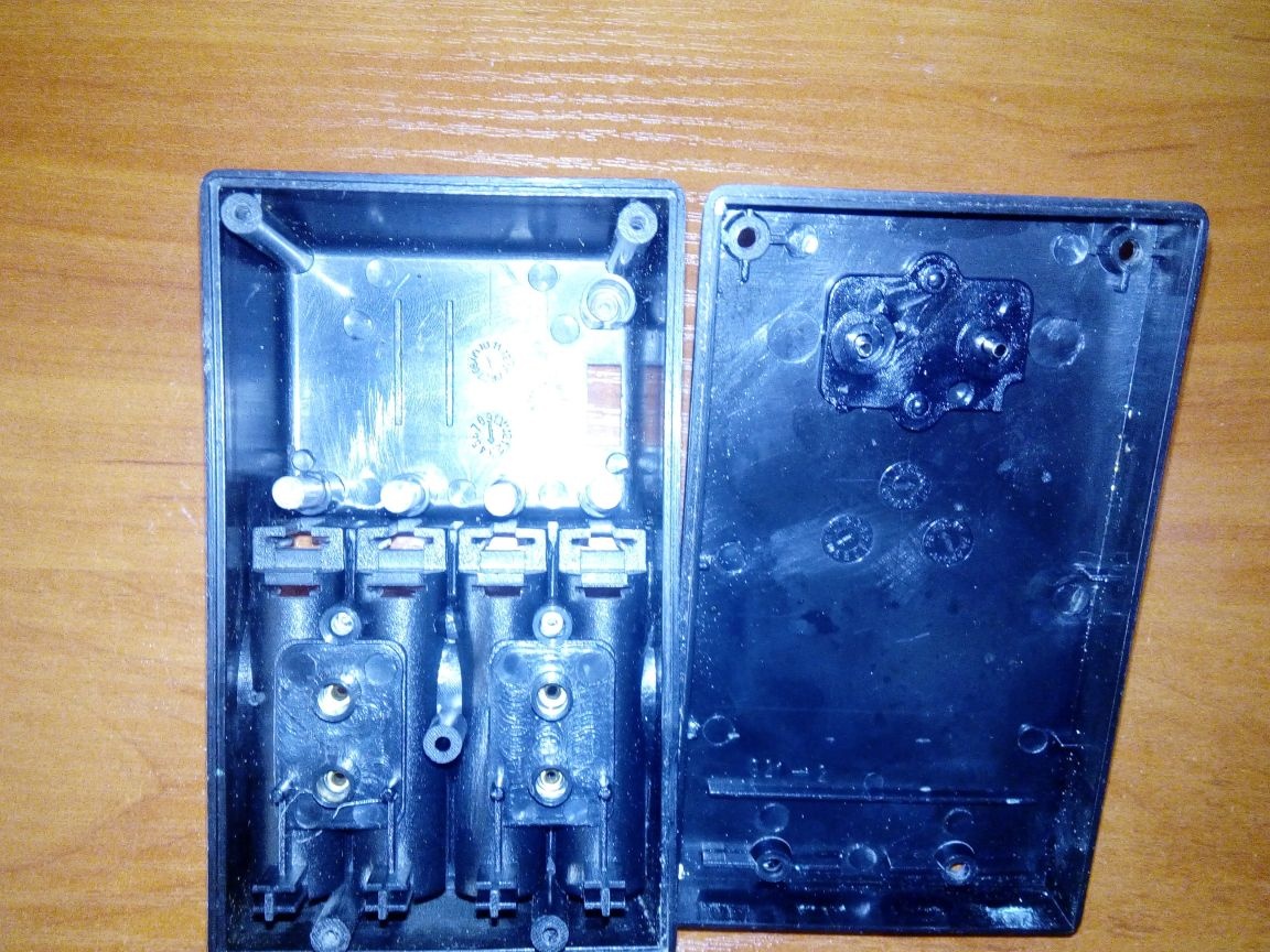
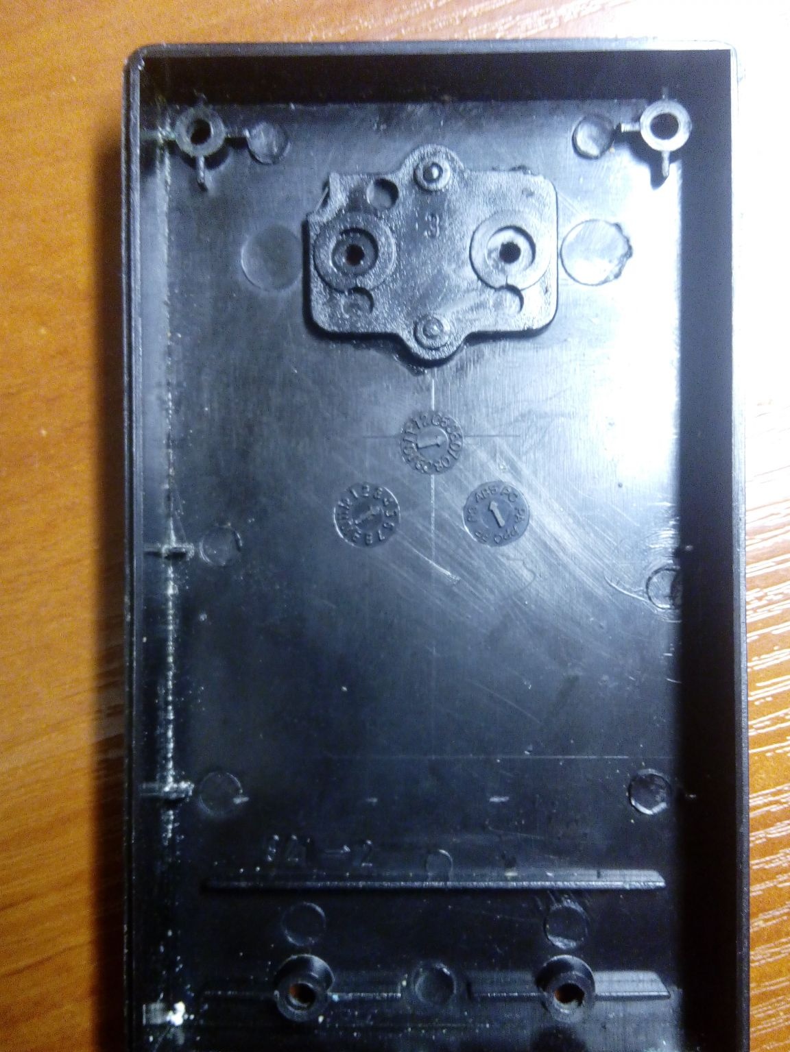
The case of the former ATABA AT-308 was slightly redone, cutting off the plug for mains power and sealed the hole formed with a plastic insert.
To connect the charger to the power supply made a short USB cable. I use the power supply with the characteristics of 5V 2.5A, which is obtained with a margin for the charger.
Conclusion
The charger performs its function - it charges batteries with a current of approximately 0.15C, which is recommended (allowed) by most manufacturers of Ni-Mh and Ni-Cd batteries. For AA type, the charging current is 260 mA, for 6F22 ("Krona") - 25 mA.
As a refinement of the circuit, it is possible to provide for the installation of an additional resistor R3 of a different nominal value with a switch to select the required charge current. Well, this is for those who will charge batteries of a different capacity or are not ready to charge for 10 hours, I didn’t have much choice - the space in the case was limited! In addition, Ni-Mh and Ni-Cd do not really like overheating when charging, so I recommend that this feature be taken into account when choosing the value of the charging current.
The undoubted advantage of this charger is the independent charge of each battery separately, which ensures its full charge, which cannot be stated when charging batteries connected in series.