

How to protect your house, cottage, apartment, garage from fire due to wiring malfunctions?
According to the Statistical Data on Fires, due to violations of the rules for the design and operation of electrical equipment, 40,390 fires occurred, in which 1,756 people died.
I. Description of the design of the device
How to protect your house, cottage, apartment, garage from a fire due to a fault in the wiring? To protect the wiring from overload and short circuits, circuit breakers, automatic plugs, ordinary plugs with fusible inserts are used. With correctly selected circuit breakers during overload, that is, when many consumers are plugged in, extension cords, tees, whose total current consumption exceeds the permissible current in the wires will occur (after a set time by the manufacturer of the circuit breaker, usually not more than 60 sec.) Thermal shutdown automatic release circuit breaker protected by this device. With a short circuit in consumers e. energy (if for some reason their internal protection fuses did not work) and in the wiring protected by this circuit breaker will happen (after a factory-set time by the manufacturer of the circuit breaker, usually no more than 0.1 sec.), the circuit-breaker will be switched off by an electromagnetic release circuit breaker protected by this device. The reliability of the wiring in the house depends on the quality of installation, a competent selection of wire and cable sections, a competent selection of protection devices. There is a lot of information on the Internet about the selection of wire and cable sections and I will not dwell on this in this article. See in more detail.
In this article, I propose for electricians, installers, and simply craftsmen who take care of their near and dear ones a simple device for checking the health of circuit breakers. Why it is a sin to conceal, in most apartments, houses, garages no one has carried out and does not check the health of circuit breakers (p. 28.4 of Appendix No. 3 PTEEP - checking the operation of protection with a power supply system with grounded neutral TNC, TNCS, TNS). Faulty, incorrectly selected author. switches are a sure way to a fire in an apartment, because in case of short circuit or overload, the wiring will not be disconnected in a timely manner.The wires will heat up due to an unacceptable current flowing through them, the insulation will light up, further igniting everything in its own way.
The reasons for which do not conduct a health check ed. there are several switches.
1. The inspection should be carried out by specially accredited electric laboratories equipped with the necessary devices and competent specialists, but this “pleasure” costs a lot of money.
2. People do not know that it is necessary to check the health of the author. circuit breakers.
3. People know, but as they say “burn it with blue fire”, maybe it will cost (But it does not cost! See the beginning of the article!).
4. Management companies do not want to conduct an audit, and residents do not require this from them.
The surest way is to conclude an agreement with the electric laboratory and the specialists will carry out the necessary checks, issue inspection protocols indicating the shortcomings. If there is money for this, then the flag is in your hands.
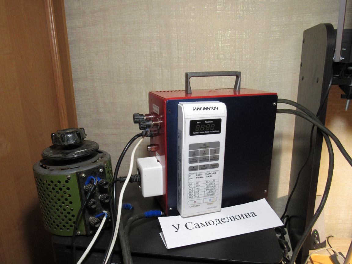
I bring to your attention the MISHINTON device made by me for checking the serviceability of circuit breakers with a rated current of up to 25A (this is almost all the circuit breakers of apartment shields, garages, cottages, houses). I foresee criticism that it is simple, primitive, etc. By the way, it will be said that RETOM -21, the device with which the author is checked. circuit breakers costs 860000 rubles (eight hundred sixty thousand rubles). Those who have that kind of money can not read further. The current source for loading can be: a power transformer from a faulty microwave, a power transformer from an old tube color TV, a step-down transformer 220 / 36V 300-400W., A home-made welding transformer.
I had a faulty microwave - the magnetron failed. Throwing away was a pity and I used electronic unit (with buttons and display) and power transformer. In the well-known circuit (see Fig. 1), the relay contacts on the circuit board of the microwave electronic unit are used as a control key, through which the LATR (laboratory autotransformer) or power (current) regulator is fed, and through it the primary winding of the power transformer. As a current regulator (instead of LATR), a power regulator is used (for 400 rubles. I bought in a radio store) a VM246 power regulator (1000W. / 220V). Maybe someone has a RT-4 regulator (previously used to adjust the brightness of the fixtures). In general, who has what. It is more convenient to use a 500W LATR for these purposes. Instead of one standard variable resistor of the power regulator 470kOhm. sequentially soldered to it at 47kOhm. (“Smoothly” and “rudely”). It is easy to set the loading current more precisely when using an additional LATR. The power regulator triac must be installed on the cooler (radiator), isolating either the radiator itself, or place a mica pad under the triac (see photo 5). Do not forget that on the insulated cooler of the triac relative to the ground there will be a phase potential! Instead of a current transformer (CT) and an ammeter I used (I just don’t have them) an M266F CLAMP METER multimeter with current clamps (I asked my son for a while).
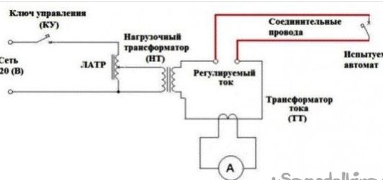
Fig 1
Instead of an electronic microwave unit, you can use an ordinary switch.
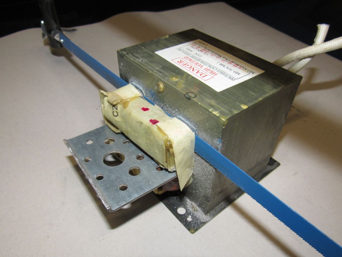
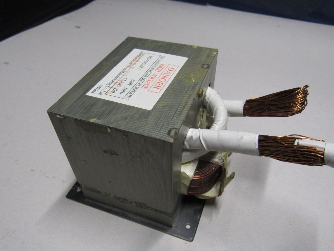
At the power transformer, it is necessary to cut the high-voltage winding with a hand hacksaw, first inserting a metal plate between the main winding and the incandescent winding so as not to damage the main winding during sawing (see photo 1).
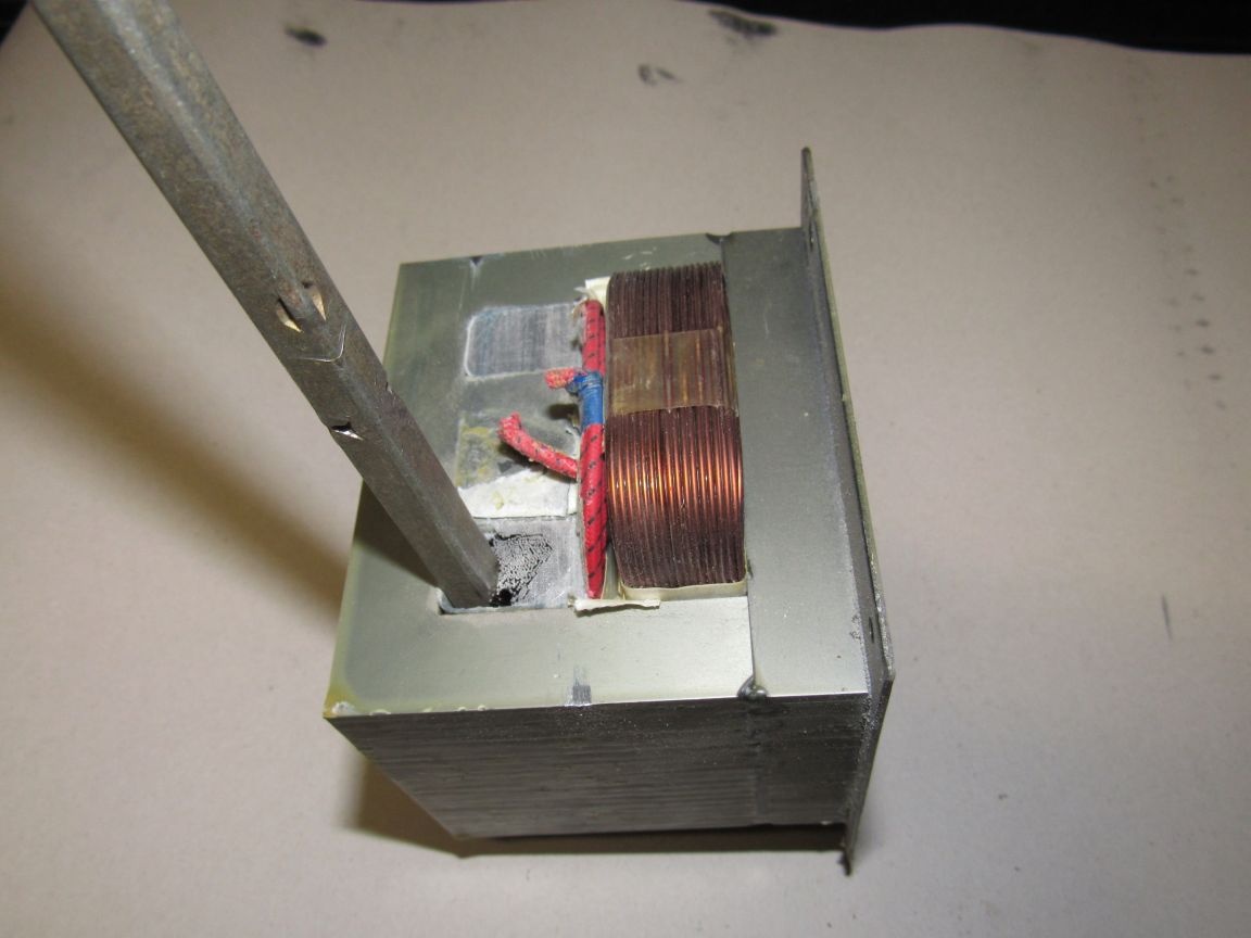
Next, knock out the remains of the winding with a punch (see photo 2)
To test the capabilities of the transformer, I brought the demagnetizing winding from the old tube TV into the open windows, folding it in half (a total of 200 wires with a diameter of 0.4 mm.). It turned out two turns (see photo 3).
The short circuit current of the secondary winding is 360A (with U-network = 220V), which is more than enough to load the author. circuit breakers. I used the box from a faulty fan heater. I recommend making homemade from 10mm. plywood, getinaksa, textolite, becauseI had to isolate the transformer and the current regulator from the case so that there was double insulation (in this case there is no need to ground the device), otherwise grounding is necessary. We immediately make a reservation to honor the rules on labor protection during the operation of electrical installations, as Ostap Bender honored the criminal code. As load cables I used stranded wires from a hose cable in rubber insulation (I had a piece of cable from a crane cable) with a cross section of 25mm.². Two fuses are installed in the MISHINTON case. One at 8A in the power supply circuit of the first winding of the power transformer, the second at 1.0A in the power supply circuit of the electronics. If you do not have a faulty microwave, then you can count the time to turn on the transformer either by the clock or by any suitable timer. You can even apply the mechanism from an old washing machine of the Volga type, it counts the time down to 6 minutes (see photo No. 4).
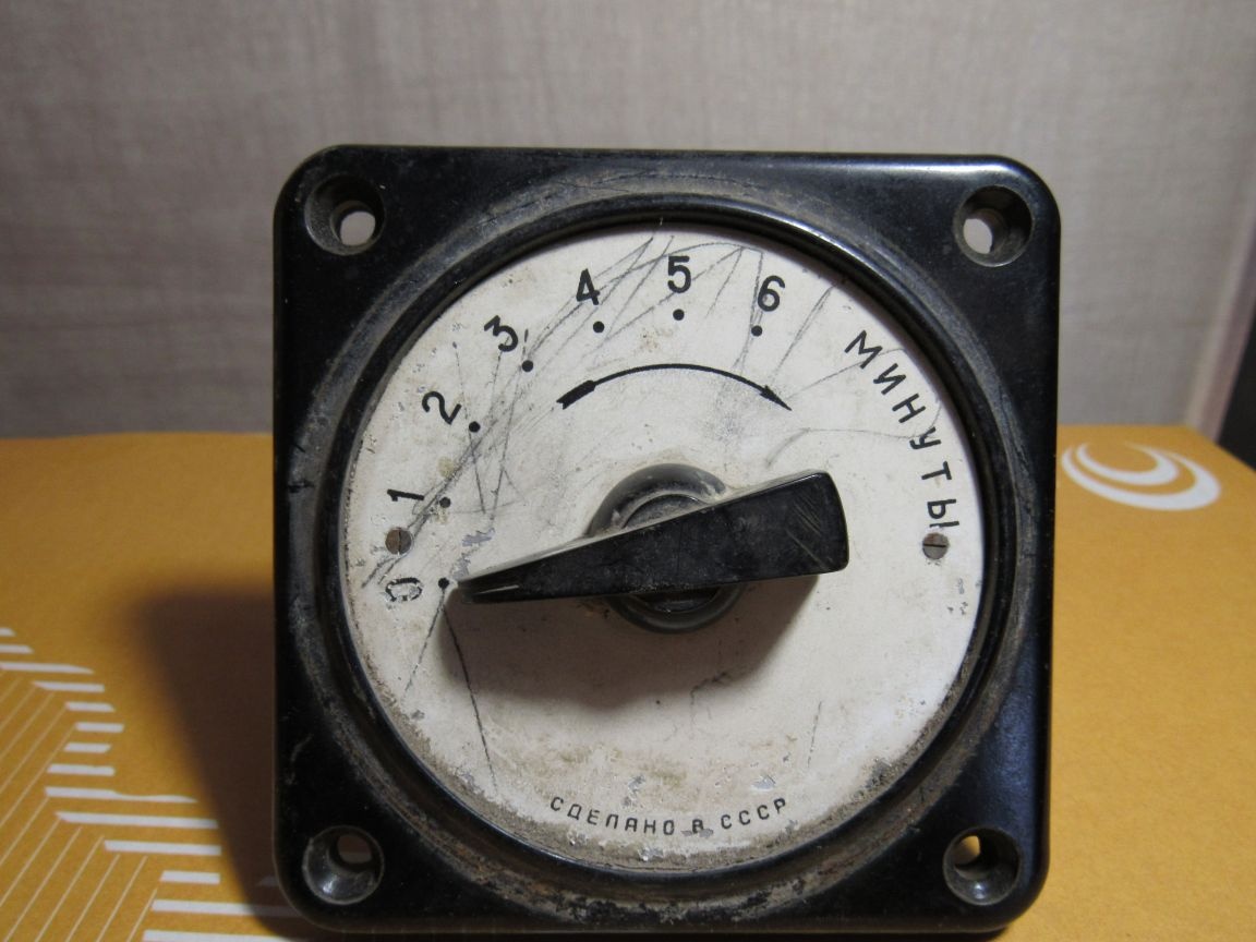
Photo 4. Clockwork from an old washing machine
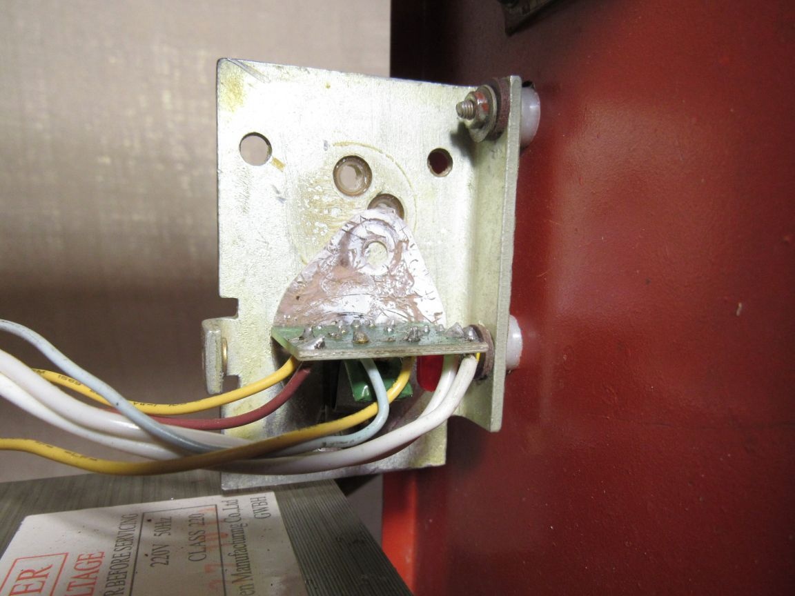
Photo 5. Isolation of a cooling cooler (radiator) together with a power regulator from the device case.
Microwave electronic unit (see photo 6)
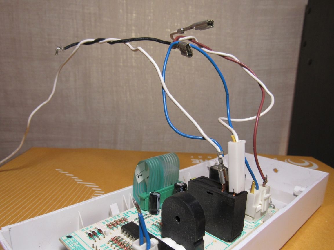
Photo 6
It serves only to establish the required operating time of the transformer and cannot turn off the transformer when the auth. switch (I bit off all unnecessary wires, I left it: 1. I soldered two blue wires on the leftmost connector. 2. At the farthest contact from the viewer, the relay left the mains cable (white) and jumper (blue), blue and white together on one contact. 3 4. At the contact near the viewer, the relay left a wire (white) that goes to power the power regulator 4. Left on the right connector are a blue jumper with a relay and a brown wire to power the power regulator, to which the black wire is soldered - the second network wire. circuit breaker (at passage through it of the loading current) I look with a glance either on the display of the microwave electronic unit, or by the clock, or on some other timer. This accuracy is quite enough in practice, because we remember that the thermal release should not work later than 1 minute. There is no difference if it worked after 20 seconds or after 35 seconds. It is important that it works !!! If someone is well versed in electronics and can modify the circuit for stopping the microwave display timer and turning off the relay when the author works. switch, then it will generally be a class. When checking the electromagnetic release ed. circuit breaker to operate on short-circuit currents time does not interest us at all, because it should work almost instantly !!!
He terminated the power wires with lugs (he used the pins (male) from the SR connector, and I use the SR connectors (mothers) for closing when setting the required current for loading) (see photo 7,8,9).
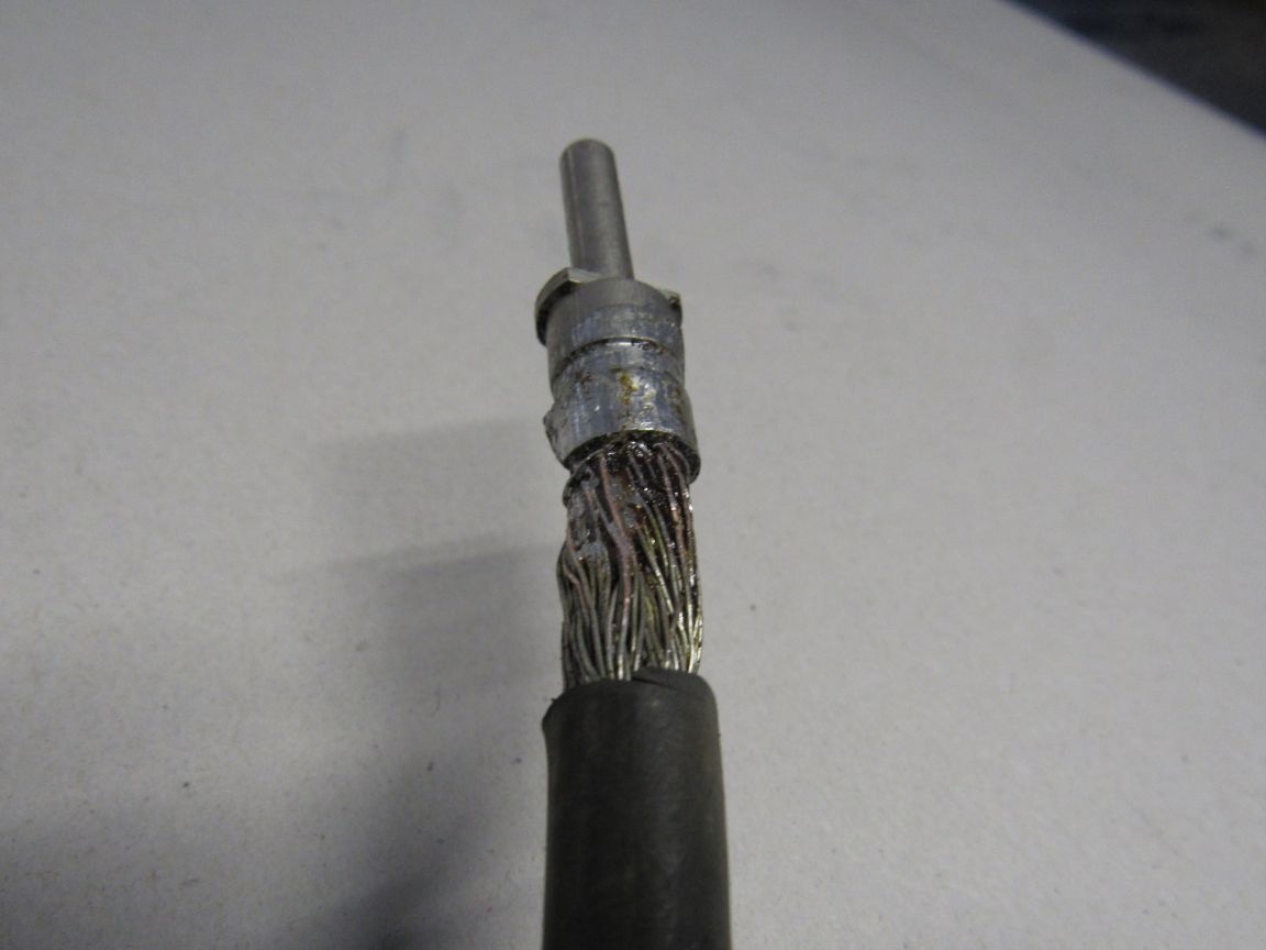
Photo 7 Terminated power wire
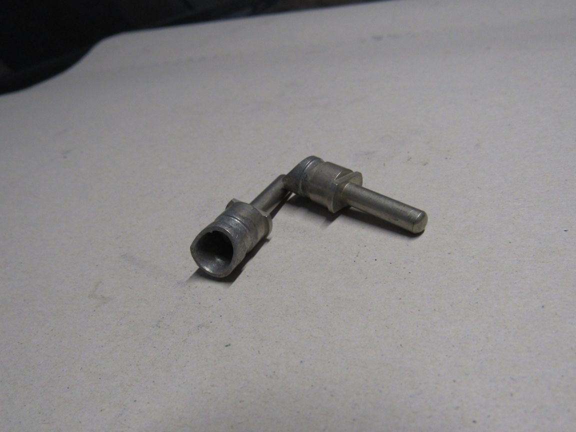
Photo 8. Pins from the connector SR (dad)
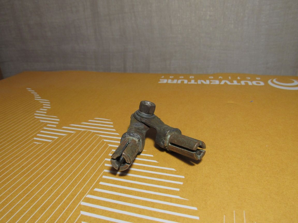
Photo 9. Closure from the SR connectors (moms)
For a smoother (and therefore more accurate) adjustment of the load current, it is better to tap from the middle of two turns. It turns out: one common wire, a tap from the middle for loading the thermal releases, because at 2 turns, the short-circuit current is 360A, and with one turn of -220A, and for this reason there will be no sharp jumps in the current during setup, and the third output for tuning the electromagnetic releases where large currents are needed.
Necessary materials for the manufacture of the device:
- power transformer from a faulty microwave, power transformer from an old tube color TV, step-down transformer 220 / 36V 300-400W., home-made welding transformer;
- timer, clock, electronic unit from the microwave;
- a finished box of suitable sizes or plywood, textolite, getinaks, etc.
- multi-wire single-core wire with a cross-section of 25mm.² (2pcs. 2 meters);
- lugs for the wire (copper or brass tubes), I used the pins and sockets from the connector SR, you can grind specially for this lugs;
- fuse holder with fuse box for 10A - 1 pc., 0.25A - 1 pc.;
- power (current) regulator 1000W .;
- if anyone has a LATR 500W .;
- a variable resistor with a nominal value less than 10 times than the standard one in the power (current) regulator;
- nuts, washers and other trifles.
I will not dwell on the small details of the design, because everyone will still do it his own way, because there is no limit to improvement.
II. The process of checking circuit breakers.
Checking the health of circuit breakers can be carried out before installing them in the shields, as well as installed in the shields of lighting.
In the case of checking author. of the switches in the lighting panels, it is necessary to de-energize the panel, check the absence of voltage and hang out the poster “Do not turn on!” on the switching device supplying this panel; People work! ”, Fold the ends of the cable that feeds the lighting shield, twist all the ends together and ground it! This work should only be done by an electrician! We agreed to comply with the requirements of labor protection rules during the operation of electrical installations, as otherwise, instead of constructing the device, you will construct a wooden box!
The question may arise: what to power the device from if there is no voltage in the shield. You can power the device from a neighbor, from a gas generator, from an uninterruptible power supply unit for a personal computer. Wires from the bus circuit breakers do not need to be disconnected, as then you can mix them up, break them off, break the switch itself.
For convenience, I pasted on the electronic unit a table of loading currents depending on the time-current characteristic and the rated current of the circuit. circuit breakers (see Fig. 2).
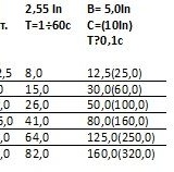
Fig. 2
It is necessary to check together. One presses the ends of the cables to the screws of the author. circuit breakers, and the other turns on the load current and monitors the time off the author. circuit breaker. Press the cable ends onto the screws of the author. circuit breakers must be with sufficient effort, but certainly not with such that to squeeze the shield into the next apartment. For the convenience of pre-setting the load current, I drilled the rivets of the faulty switch, disconnected the halves of the case and blocked the on-off lever of the switch with a paper stopper (see photo 10), then put everything back in place and connected the halves with screws. The fountain pen shows the place where the plug is inserted to lock the switch.
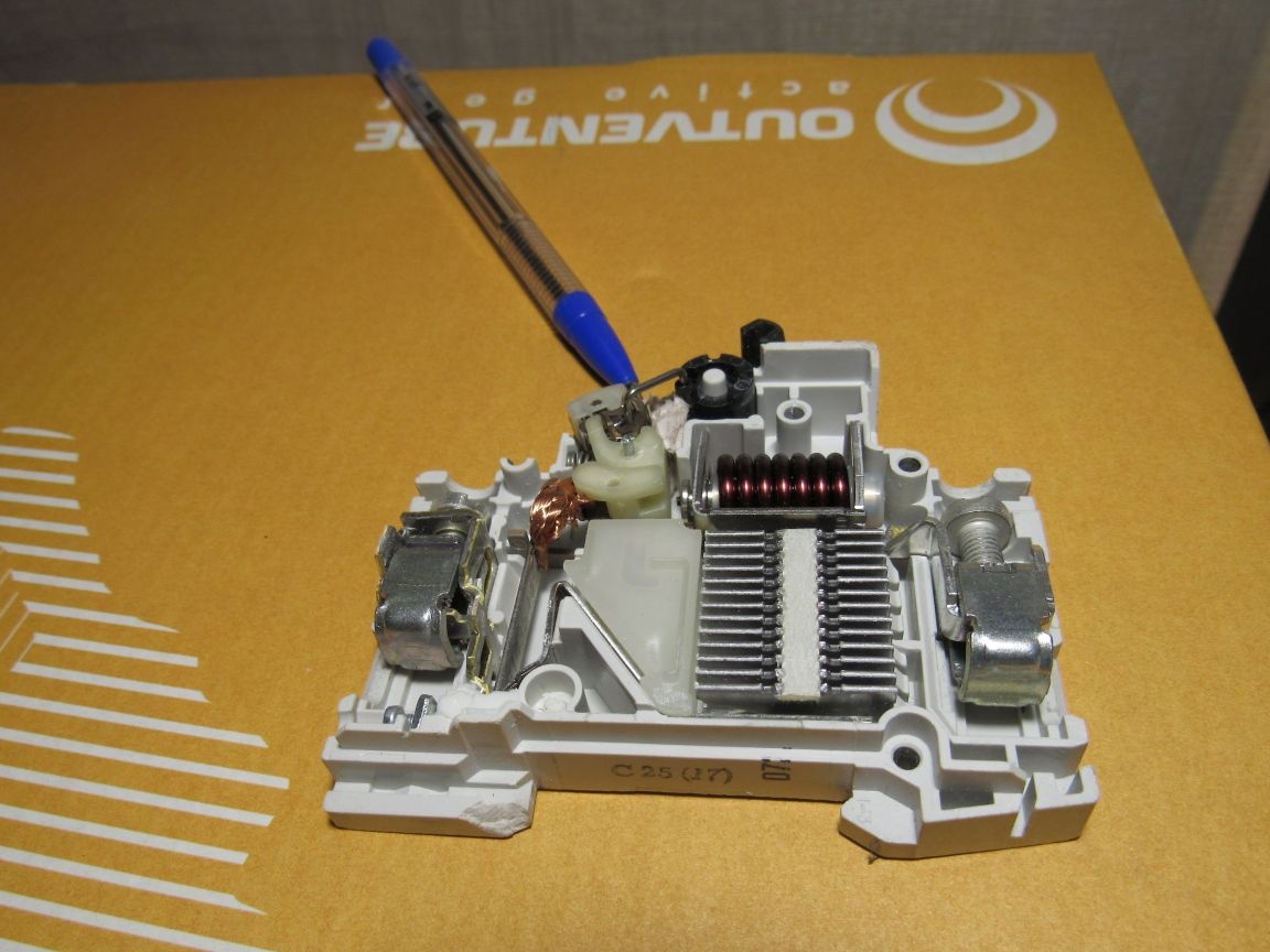
Photo 10
Of faulty auth. circuit breakers, it is necessary to select typical representatives: 2.5A, 6A, 10A, 16A, 25A and lock the switch with them, so that when the current is set, the releases will not work. These "loads" are used to preset the required current, then we connect the tested auth. switch and, without breaking the settings, turn on the load, immediately correcting the current.
Watch the video in more detail: