

I will continue the story about the design of a liquid fuel carburetor for a glass-blowing workshop. I recommend that you familiarize yourself with the detailed description of the system and the manufacture of a gas trap:
Part 1. System Description, gas trap
I turn to the heart of the installation - the bubbler. In principle, this part of the described carburetor can well be used as a simple independent carburetor, very often they do just that, but at the same time, the operation of the device becomes more complicated and only fresh gas has to be used (in the absence of heating). It is possible to slightly improve the consumer properties of the bubbler with independent use by supplementing the design with a bypass with a regulating (needle) tap. This will allow you to adjust the saturation of the resulting combustible mixture with gasoline vapors.
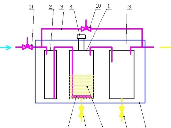
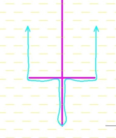
A diagram of the bubbler device is shown in the figure. The bubbler 1 has the form of a sealed vessel with a neck for filling gasoline with a screw cap 4. Two tubes are soldered into the vessel - a long one, reaching the bottom and ending with an air atomizer 6 and a short one, for air to escape with gasoline vapors. A drain cock has been soldered to the bottom of the vessel, allowing draining heavy fuel residues with water.
There are various, including much simpler devices for atomizing air, it is useful to mention them. Gasoline is a solvent and many adhesives and plastics break down in it. The design should be made of metal, copper is most often used - it is easy to solder and bend. Typically, an air atomizer has the form of a spiral or ring from a copper tube parallel to the bottom, with many small holes. This design allows you to increase the area of contact of air with gasoline and increase its evaporation. However, simpler constructions are often used - a vertical tube, somewhat not reaching the bottom with a narrowed hole. The simple and technological design of the sprayer, which has slightly better efficiency, has the appearance of a vertical tube, the end of which reaches the bottom and is plugged. At the end of the tube there are several small holes, above them, a large washer is soldered to the tube.
There is an alternative way to increase air saturation with gasoline vapors in a bubbler.To do this, a large number of small glass balls or pipe scraps are laid in a vessel with gasoline, which increases the path of air bubbles and allows them to contact the liquid longer.
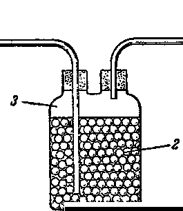
Sometimes, instead of glass filling, large metal shavings are used.
What was used in the work.
Tools, equipment.
All connections were made by soldering - you need a small gas burner. Set of bench tools. Medium size abrasive sanding pad for sanding soldering spots. For an accurate cut of copper tubes, it is convenient to use an end pendulum saw, or a miter box with a hacksaw will do. It came in handy electric grind, bench vise.
Materials
In addition to the samovar itself, scraps of sheet copper and brass, copper tubes of 15 mm, 6 mm diameter were used. Tin-copper solder No. 3, flux to it. Brush.
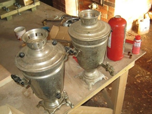
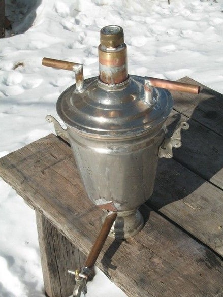
The bubbler was made from an old electric samovar. Capacity 4l, body made of nickel-plated brass. Or chrome plated.
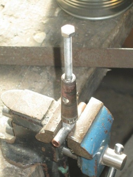
After disassembling using penetrating grease to unscrew heavily rusted fasteners, the samovar was scrubbed as far as possible. The crane cut off with a hacksaw leaving a small thick-walled pipe soldered into the wall of the body. The wall thickness made it possible to drill an internal channel for the passage of a copper 6mm tube, plugged at the end. In a tube in grinding, the digital temperature sensor DS18B20 in the TO-92 case was located.
Initially, it was decided, as a gasoline heater, to use a standard TEN of a samovar, fortunately, one of them turned out to be intact. The threads were cut and replaced by soldering. Unfortunately, the heater turned out to be defective - its brass shirt was leaking in several places and had to be replaced with a four less powerful heater from the “glass” boiler soldered into the side wall of the case, so that the heater would hide in the thickness of the liquid, even with a small amount fuel.
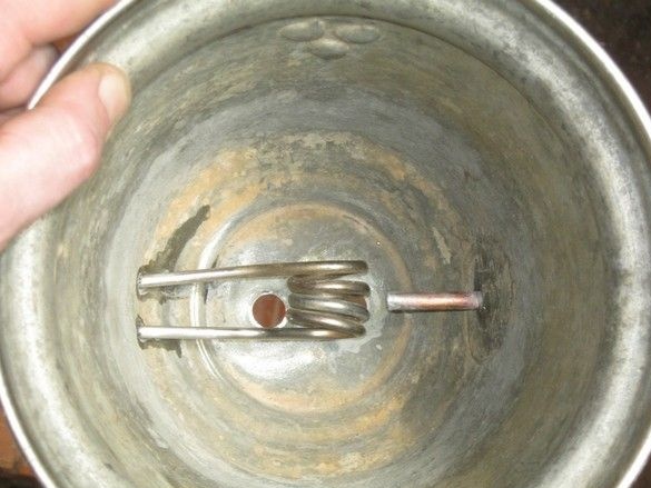
During the tests, a leak was detected on the heater body - the whole structure was beating current and also had to be abandoned in favor of an external heater from the heating cable. The heater was removed, the holes were sealed with a copper plate.
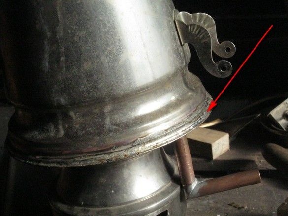
To drain heavy non-volatile residues of fuel and water, a descent was organized. An 18mm copper pipe was cut off at the end saw, so that the cut covered both holes at the bottom of the standard heater and the drain was slightly inclined towards the faucet. Among other things, such a slice made it possible to make the place of soldering very durable mechanically.
At the end of the tube, a clipped crane from the same samovar, a cork type, was soldered. Some disagreement between the diameters of the tube and the faucet nozzle was neutralized by winding from stripped copper wire.
All the soldering was performed with soft tin-copper solder No. 3, used for the installation of copper water supply, and a special flux paste for it. Soldering is carried out by a gas burner.
The cork faucet was finalized - a regular "samovar" handle, was replaced by a piece of copper tube, the faucet plug, spring-loaded. To install the spring, a small socket was drilled in the cork, where a piece of the M5 bolt was soldered.
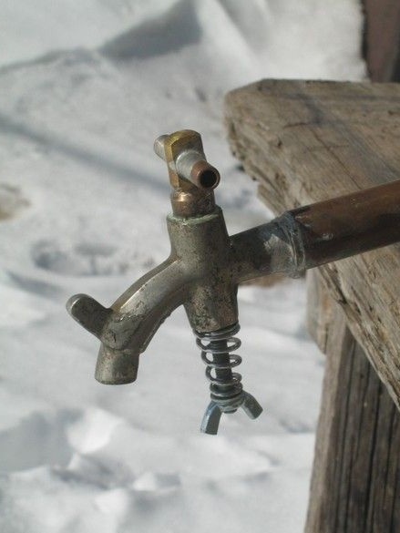
The crane assembly. Cone spring, perfect fit from the powder fire extinguisher valve. With minimal tightening, the crane turns tightly and with some effort. For a larger adjustment range, the stiffness of the spring can be slightly reduced by etching it in acid.
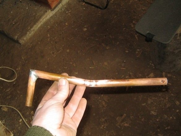
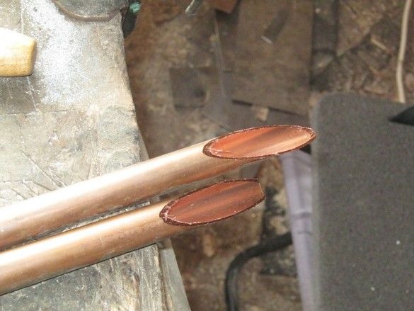
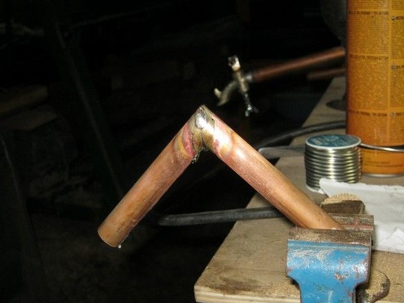
A long tube ending with an air atomizer on the lid of the tank should reach the bottom and be close to the inclined wall. I had to bend it a little. In order not to get involved with bending and packing with sand, the pipe was bent by making a few incomplete cuts with a hacksaw for metal, closing their edges and sealing this place. He made an angle of 90 degrees by cutting off the ends of the tube blanks at 45 degrees on the end saw, folding and soldering them.
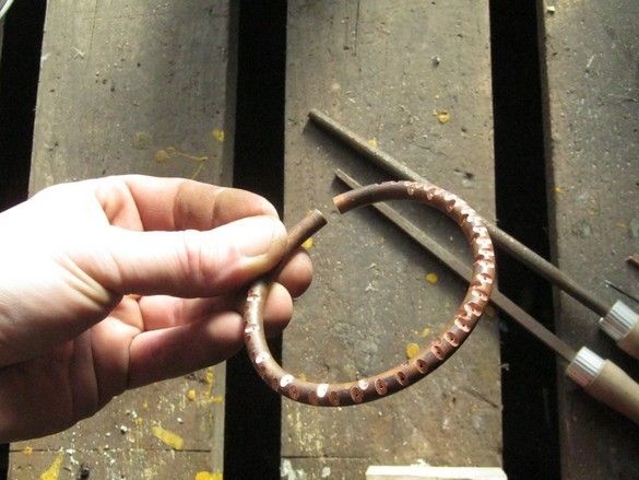
The atomizer itself, inserted into the lower end of the muffled curved tube, was made from a thin copper tube. Pre-annealed tube, bent a ring on a machined wooden blank. He made the holes, punctured with a thin awl, the tube wall previously thinned with a file. In two rows over the entire diameter of the ring.
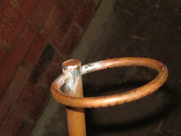
I soldered the spray into the side walls of a long tube, drowning out the end simultaneously with a large piece of copper plate of suitable thickness. Washed off the flux, sawed off the excess.
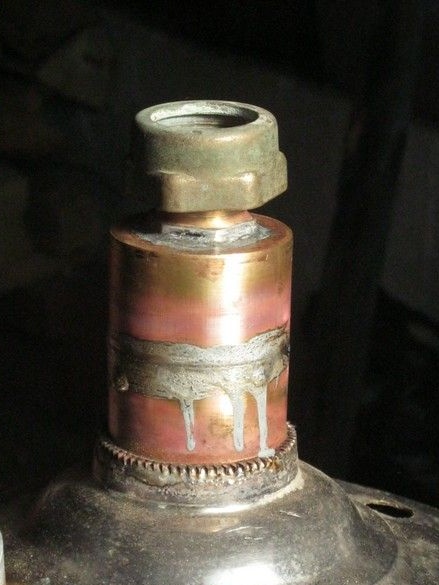
After thoroughly cleaning the adjacent surfaces and applying flux, the tank cap was sealed. Previously, holes of significant diameter were drilled in the lid, so that a round file passed through them, then the holes were bored to the desired diameter - two for 15 mm copper tubes, one large, in the middle, for the filler neck.
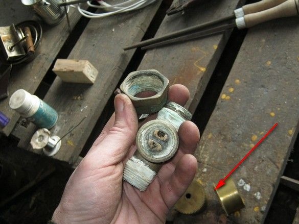
For the filler neck with cork, several suitable pieces of bronze and brass were selected. The neck itself must be high enough to protrude from the sand filling of the apparatus. The threaded inch plug was made of parts from the water supply system, the neck was welded from two cases of factory springs, from dismantled desktop mechanical watches.
Cork blank, plugged. I soldered a piece of a thick brass plate into it. Another brass circle of the same diameter is simply inserted into the cork and will not allow the rubber gasket to wrinkle when twisting.
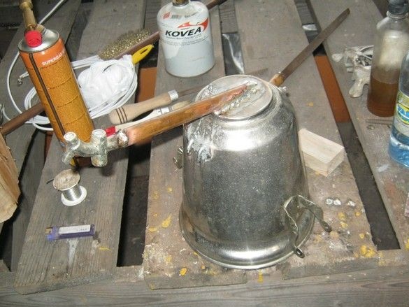
I made a short tube for the exit of the finished combustible mixture in a similarly long way - the edges of the workpieces are cut at 45 degrees on a low-feed end saw, folded, greased with flux paste and soldered with a gas burner. You can on a brick, you can like that in a vice. Yes, you need to cut the coppers on the pendulum saw with glasses - the flying particles of copper are much heavier than the wooden ones and fly quite far.
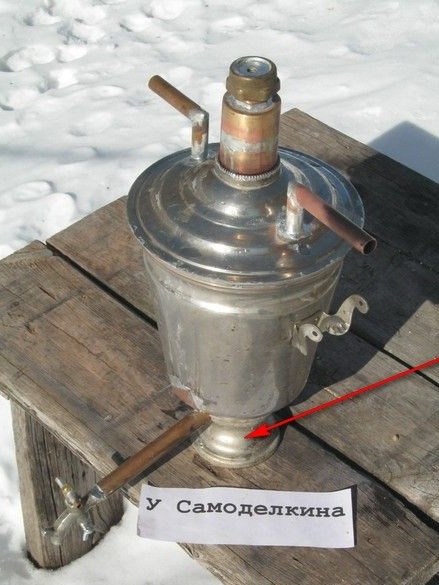
After sealing the gas pipes and checking the tightness with soap foam, a stand was installed on the bubbler tank (part from the samovar). The angle grinder was cut in it for the outlet of the drain pipe, the edges were cleaned with a sandpaper, the stand was soldered to the body at three points.
Finally, the finished bubbler is thoroughly washed once again from the flux, including inside. The sprayer is blown, and the solder droplets that have got inside are removed. Before use, the valve plug should be lubricated.
In conclusion, it should be said that for angular joints, it is better to use standard parts - parts of a copper water supply, this will make the structure somewhat stronger and more technologically advanced.
Part 3. Buffer tank assembly.