
1 Device concept
The purpose of this development is to collect data from local sensors, send this data to the Internet. The user will be able anywhere in the world to view the data coming from the sensors and remotely make a decision on the activation of certain actuators that will be located locally, next to the sensors
The project uses Arduino UNO and WiFi module ESP8266-01. Data will be transmitted to the cloud through the ThingSpeak.com web service, and devices will be activated through the android application developed using the MIT AppInventor.
IoT is a concept of a computer network of physical objects (“things”) equipped with built-in technologies for interacting with each other or with the external environment, considering the organization of such networks as a phenomenon that can rebuild economic and social processes, eliminating the need for human participation from part of actions and operations.
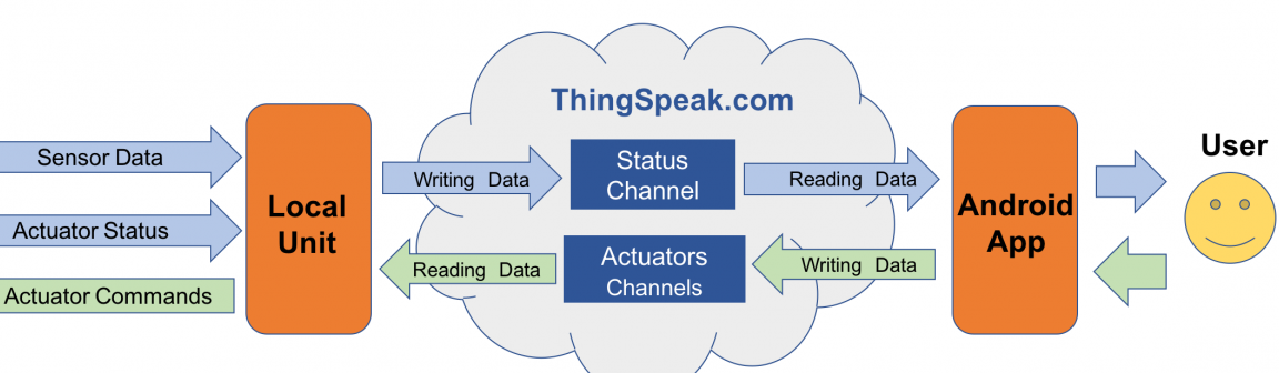
The main focus of this IoT project will be the ThingSpeak.com service. The local UNO / ESP-01 device receives data from sensors and data on the status of actuators, sends it to the Internet “recording” through a specific ThingSpeak.com status channel (ThingSpeak.com Status Channel), the same local device receives data, " reading ”them from another data channel -“ the channel of executive devices ”(ThingSpeak.com Actuator Channels).
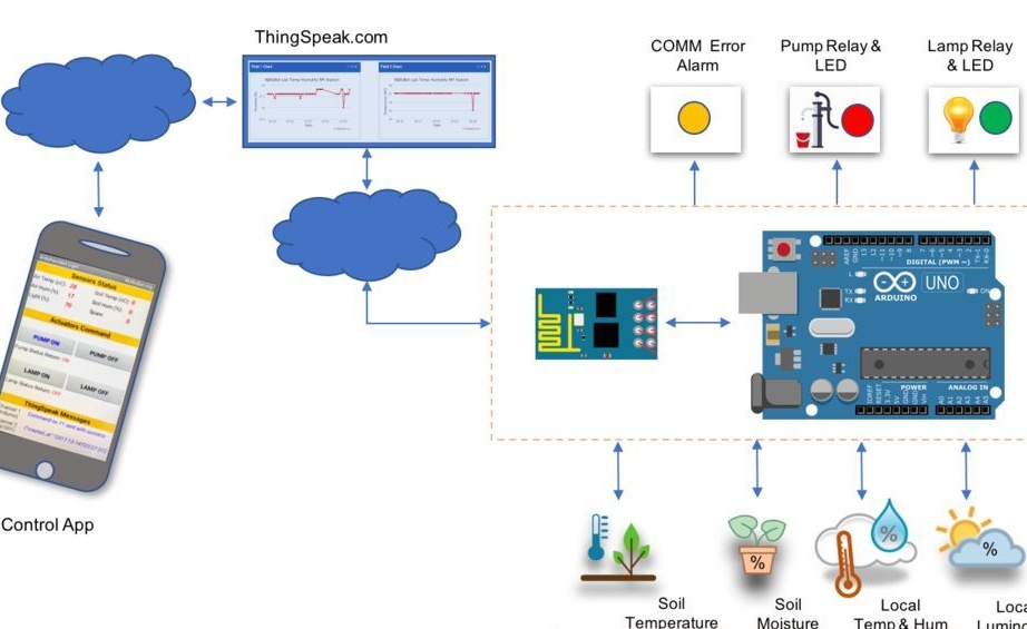
Data will be collected using a temperature and relative humidity sensor, soil temperature and humidity, and an ambient light sensor. This data will be sent to the ThingSpeak service cloud.
There will be two executive devices - this is a water electric pump and a lamp. Their ON / OFF status will also be sent to the cloud. Data from sensors, for example, can display the current state of a greenhouse or greenhouse. The user will control the executive devices using the android application.
2 List of required components
All links are for informational purposes only.
2 x LEDs (red and green)
1 x
- $3.00
220V lamp
2 x 330 ohm resistor (used with LEDs)
2 x 10K ohm resistor (used with DHT22 and LDR)
1 x 4K7 ohm resistor (used with DS18B20)
Bread board
Jumpers
External power supply for relay 5V DC
3 Iron part
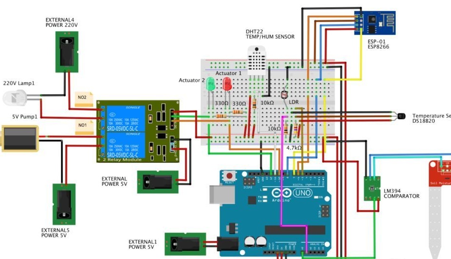
Now you need to connect all the sensors, as shown in the diagram.
The ideal solution would be to assemble and test the project in parts.
In the following sequence:
1. Install and test all sensors
2.Install and minimum configure ESP-01
3. Change the ESP-01 setup to the final configuration and test
4. Configure ThingSpeak Status Channel
5. Install ThingSpeak code on Arduino and check the status of sensors on the cloud
6. Develop the first version of the program on android to check status messages from sensors
7. Install actuators
8. Configure ThingSpeak Actuators channels
9. Install and test code for executive devices on Arduino
10. Make the second version of the program on android for the entire device assembly.
4 Sensor Connection
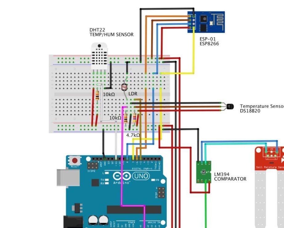
The project uses some libraries that are included in. It is necessary to check their availability. The initial configuration of these libraries is as follows:
// DS18B20
#include
#include
#define ONE_WIRE_BUS 5 // DS18B20 on pin D5
OneWire oneWire (ONE_WIRE_BUS);
DallasTemperature DS18B20 (& oneWire);
int soilTemp = 0;

// DHT
#include "DHT.h"
#include
int pinoDHT = 11;
int tipoDHT = DHT22;
DHT dht (pinoDHT, tipoDHT);
int airTemp = 0;
int airHum = 0;

// LDR (Light)
#define ldrPIN 1
int light = 0;

// Soil humidity
#define soilHumPIN 0
int soilHum = 0;
Now we initialize our sensors and display them in the terminal:
void setup ()
{
  Serial.begin (9600);
  DS18B20.begin ();
  dht.begin ();
}

void loop ()
{
  readSensors ();
  displaySensors ();
  delay (10000);
}
And finally, we will write two functions: one reads the readings from the sensors, and the other displays them on the screen:
/ ********* Read Sensors value ************* /
void readSensors (void)
{
airTemp = dht.readTemperature ();
airHum = dht.readHumidity ();
DS18B20.requestTemperatures ();
soilTemp = DS18B20.getTempCByIndex (0); // Sensor 0 will capture Soil Temp in Celcius
soilHum = map (analogRead (soilHumPIN), 1023, 0, 0, 100);
light = map (analogRead (ldrPIN), 1023, 0, 0, 100); // LDRDark: 0 ==> light 100%
}
/ ********* Display Sensors value ************* /
void displaySensors (void)
{
Serial.print ("airTemp (oC):");
Serial.println (airTemp);
Serial.print ("airHum (%):");
Serial.println (airHum);
Serial.print ("soilTemp (oC):");
Serial.println (soilTemp);
Serial.print ("soilHum (%):");
Serial.println (soilHum);
Serial.print ("light (%):");
Serial.println (light);
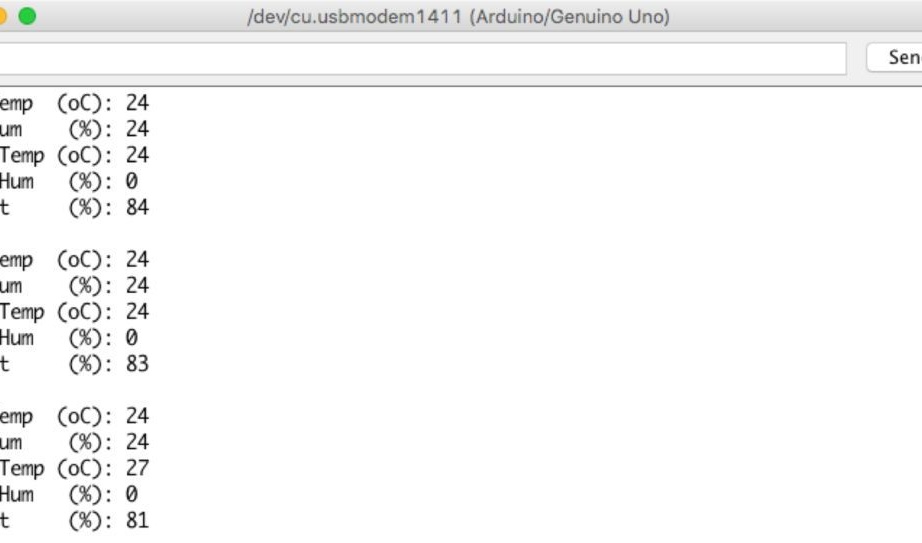
Serial.println ("");
}The photo shows how the data is displayed on the screen.
Source code can be downloaded from the author.
4 ESP8266-01 basic configuration
The fastest way to "talk" with the module is the AT command. The processor already has an AT command processor. By default, the module comes with factory settings of 115200 baud, you need to set 9600 baud in the settings.
Firstly, you need to connect the module, as shown in the photo
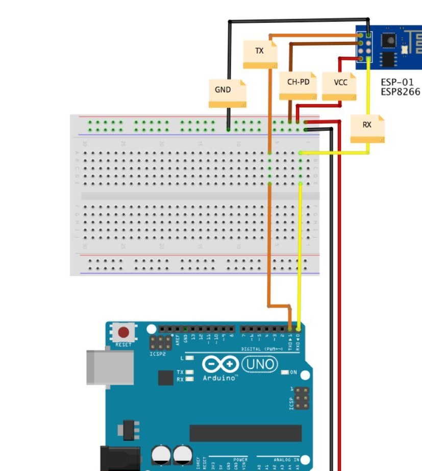
( Note that the Tx terminal of the ESP-01 is connected to the Tx terminal of UNO, just like the Rx terminals are connected to each other. This connection will be changed later. ).
Then connect UNO to the computer, open the IDE and download the example that is located. This is empty code so that there are no conflicts between ESP-01 and UNO. This code was uploaded to Ardunio before connecting the ESP-01 to it, in order to be sure that Ardunio will not use the Tx and Rx pins for anything else.
Now you need to open the IDE Serial Monitor, set the baud rate to 115200 in the settings and send the AT command to the IDE Serial Monitor. ESP-01 should send an answer OK
Now you need to change the data rate in the ESP-01 module. To do this, in the IDE, give the command
AT + CIOBAUD = 9600It may happen that the ESP-01 returns to the factory settings, then you will need to use another command:
AT + UART_DEF = , , , , For instance 9600 baud / 8 data bits / 1 stop bits and none parity and flow control
AT + UART_DEF = 9600,8,1,0,0Now change the data transfer rate in the IDE settings to 9600 and send the AT command, the OK response should come.
Next, you need to switch the module to STA mode so that it can connect to the access point of your network.
AT + CWMODE = 1For the module to connect to the network, enter the command AT + CWJAP = "network_name", "network_name_1"where network_name Is the name of your network, and network_name_1 - password for your network (password and network name must be in quotation marks)
If you see the answer WIFI CONNECTED WIFI GOT IP, then the connection is established. Verify the IP address with the command
AT + CIFSRThe address that appears in your monitor, you can use in the future. Once you have configured the module, you can connect it permanently, but for this you need to change its switching circuit, as shown in the figure.
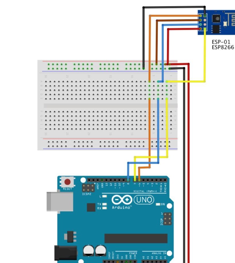
• ESP-01 RX (Yellow) -> UNO Pin D7
• ESP-01 TX (Orange) -> UNO Pin D6
• ESP-01 Ch-Pd (Brown) -> Vcc (3.3V)
• ESP-01 Reset (Blue) -> UNO Pin D8
• ESP-01 Vcc (Red) -> 3.3V
• ESP-01 Gnd (Black) -> UNO GND
Note that the Software Serial library uses the UNO Pin D7 pin like tx and it connects to the output of ESP-01 Rxwhile UNO Pin D6 like rxconnected to ESP-01 TX.
Enter a small code in order to check the correct connection and configuration of the ESP-01 module
#include
SoftwareSerial esp8266 (6.7); // Rx ==> Pin 6; TX ==> Pin7

#define speed8266 9600

void setup ()
{
  esp8266.begin (speed8266);
  Serial.begin (speed8266);
  Serial.println ("ESP8266 Setup test - use AT coomands");
}

void loop ()
{
  while (esp8266.available ())
  {
    Serial.write (esp8266.read ());
  }
  while (Serial.available ())
  {
    esp8266.write (Serial.read ());
  }
}
Now a few AT teams. See the results in the Serial Monitor.
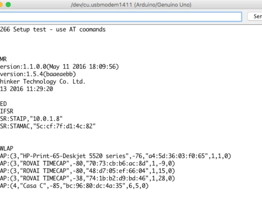
* AT =====> ESP8266 returns OK
* AT + RST =====> ESP8266 restart and returns OK
* AT + GMR =====> ESP8266 returns AT Version; SDK version; id; Ok
* AT + CWMODE? => ESP8266 returns mode type
* AT + CWLAP ===> ESP8266 returns close access points
* AT + CIFSR ===> ESP8266 returns designided IP
Program code can be downloaded at
6 connection of sensors and ESP-01
After all the sensors are connected and checked, as well as the ESP-01 module is checked, it is necessary to prepare the data for sending to the Internet.
7 ThingSpeak
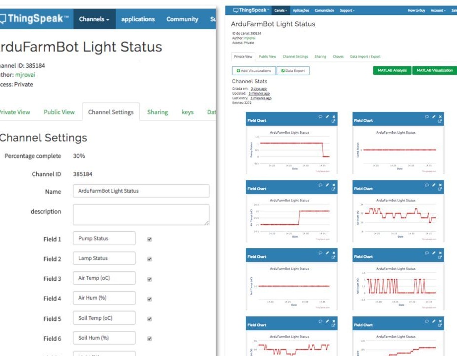
One of the most important parts of the project is the open IoT platform, which will allow you to collect data from sensors, process and analyze them. To do this, go to and create your account. Next, you need to create a channel where there will be 2 actuators, 5 sensors and one backup field.
• Field 1: Actuator 1 (device 1)
• Field 2: Actuator 2 (device 2)
• Field 3: Air Temperature in oC (air temperature in degrees Celsius)
• Filed 4: Air Relative Humidity in% (Relative humidity in%)
• Field 5: Soil Temperature in oC (Soil temperature in gr. Celsius)
• Field 6: Soil Humidity in% (soil moisture in%)
• Field 7: Luminosity in% (illumination in%)
• Field 8: Spare
Field 8 is reserved for future expansion or for debugging. In this project, it is used as a communication error counter between Arduino / ESP-01 and ThingSpeak.com.
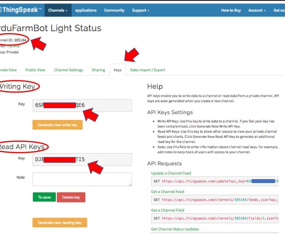
Once you have created the Status Channel, you need to record the keys, as shown in the photo.
8 Sending sensor status to the cloud
At the moment, we have a configured cloud service and our sensors collect data locally. Now you need to take this data and send it to the cloud on ThingSpeak.com.
In order to write data to the ThingSpeak channel, you need to send a GET string. This will be done in three stages.
Send the command "Start cmd"
AT + CIPSTART = "TCP", "184.106.153.149", 80
Further string length
AT + CIPSEND = 116And finally, a GET string that will write our data in the reserved Status Channel fields.
GET / update? Api_key = your_saved_key_here & field1 = pump & fieldlamp = 0 & field3 = airTemp & field4 = airHum & field5 = soilTemp & field6 = soilHum & field7 = light & field8 = sparePlease note that we should not write data to the channel more than 1 time in 16 seconds.
The submitted code will do all this.
// Thingspeak
String statusChWriteKey = "YOUR WRITE KEY HERE"; // Status Channel id: 385184

#include
SoftwareSerial EspSerial (6, 7); // Rx, Tx
#define HARDWARE_RESET 8

// DS18B20
#include
#include
#define ONE_WIRE_BUS 5 // DS18B20 on pin D5
OneWire oneWire (ONE_WIRE_BUS);
DallasTemperature DS18B20 (& oneWire);
int soilTemp = 0;

// DHT
#include "DHT.h"
#include
int pinoDHT = 11;
int tipoDHT = DHT22;
DHT dht (pinoDHT, tipoDHT);
int airTemp = 0;
int airHum = 0;

// LDR (Light)
#define ldrPIN 1
int light = 0;

// Soil humidity
#define soilHumPIN 0
int soilHum = 0;

// Variables to be used with timers
long writeTimingSeconds = 17; // ==> Define Sample time in seconds to send data
long startWriteTiming = 0;
long elapsedWriteTime = 0;

// Variables to be used with Actuators
boolean pump = 0;
boolean lamp = 0;

int spare = 0;
boolean error;

void setup ()
{
  Serial.begin (9600);

  pinMode (HARDWARE_RESET, OUTPUT);

  digitalWrite (HARDWARE_RESET, HIGH);

  DS18B20.begin ();
  dht.begin ();

  EspSerial.begin (9600); // Comunicacao com Modulo WiFi
  EspHardwareReset (); // Reset do Modulo WiFi
  startWriteTiming = millis (); // starting the "program clock"
}

void loop ()
{
  start: // label
  error = 0;

  elapsedWriteTime = millis () - startWriteTiming;

  if (elapsedWriteTime> (writeTimingSeconds * 1000))
  {
    readSensors ();
    writeThingSpeak ();
    startWriteTiming = millis ();
  }

  if (error == 1) // Resend if transmission is not completed
  {
    Serial.println ("<<<< ERROR >>>>");
    delay (2000);
    goto start; // go to label "start"
  }
}

/ ********* Read Sensors value ************* /
void readSensors (void)
{
  airTemp = dht.readTemperature ();
  airHum = dht.readHumidity ();

  DS18B20.requestTemperatures ();
  soilTemp = DS18B20.getTempCByIndex (0); // Sensor 0 will capture Soil Temp in Celcius

  light = map (analogRead (ldrPIN), 1023, 0, 0, 100); // LDRDark: 0 ==> light 100%
  soilHum = map (analogRead (soilHumPIN), 1023, 0, 0, 100);

}

/ ********* Conexao com TCP com Thingspeak ******* /
void writeThingSpeak (void)
{

  startThingSpeakCmd ();

  // preparacao da string GET
  String getStr = "GET / update? Api_key =";
  getStr + = statusChWriteKey;
  getStr + = "& field1 =";
  getStr + = String (pump);
  getStr + = "& field2 =";
  getStr + = String (lamp);
  getStr + = "& field3 =";
  getStr + = String (airTemp);
  getStr + = "& field4 =";
  getStr + = String (airHum);
  getStr + = "& field5 =";
  getStr + = String (soilTemp);
  getStr + = "& field6 =";
  getStr + = String (soilHum);
  getStr + = "& field7 =";
  getStr + = String (light);
  getStr + = "& field8 =";
  getStr + = String (spare);
  getStr + = "\ r \ n \ r \ n";

  sendThingSpeakGetCmd (getStr);
}

/ ********* Reset ESP ************* /
void EspHardwareReset (void)
{
  Serial.println ("Reseting .......");
  digitalWrite (HARDWARE_RESET, LOW);
  delay (500);
  digitalWrite (HARDWARE_RESET, HIGH);
  delay (8000); // Tempo necessário para começar a ler
  Serial.println ("RESET");
}

/ ********* Start communication with ThingSpeak ************* /
void startThingSpeakCmd (void)
{
  EspSerial.flush (); // limpa o buffer antes de começar a gravar

  String cmd = "AT + CIPSTART = \" TCP \ ", \" ";
  cmd + = "184.106.153.149"; // Endereco IP de api.thingspeak.com
  cmd + = "\", 80 ";
  EspSerial.println (cmd);
  Serial.print ("enviado ==> Start cmd:");
  Serial.println (cmd);

  if (EspSerial.find ("Error"))
  {
    Serial.println ("AT + CIPSTART error");
    return
  }
}

/ ********* send a GET cmd to ThingSpeak ************* /
String sendThingSpeakGetCmd (String getStr)
{
  String cmd = "AT + CIPSEND =";
  cmd + = String (getStr.length ());
  EspSerial.println (cmd);
  Serial.print ("enviado ==> lenght cmd:");
  Serial.println (cmd);

  if (EspSerial.find ((char *) ">"))
  {
    EspSerial.print (getStr);
    Serial.print ("enviado ==> getStr:");
    Serial.println (getStr);
    delay (500); // tempo para processar o GET, sem este delay apresenta busy no próximo comando

    String messageBody = "";
    while (EspSerial.available ())
    {
      String line = EspSerial.readStringUntil ('\ n');
      if (line.length () == 1)
      {// actual content starts after empty line (that has length 1)
        messageBody = EspSerial.readStringUntil ('\ n');
      }
    }
    Serial.print ("MessageBody received:");
    Serial.println (messageBody);
    return messageBody;
  }
  else
  {
    EspSerial.println ("AT + CIPCLOSE"); // alert user
    Serial.println ("ESP8266 CIPSEND ERROR: RESENDING"); // Resend ...
    spare = spare + 1;
    error = 1;
    return "error";
  }
}
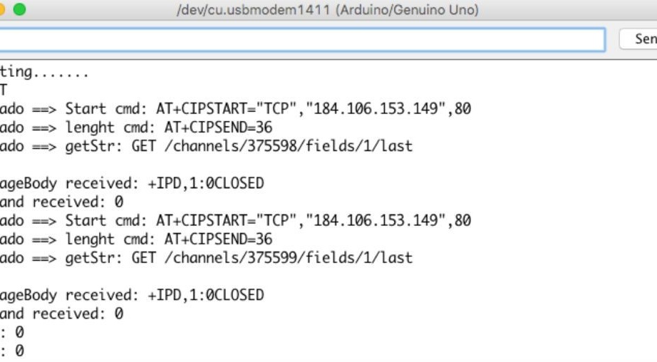
You can see the progress in the Serial Monitor.
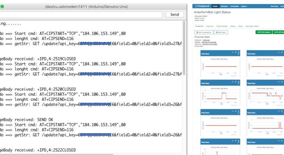
Source code can be downloaded at
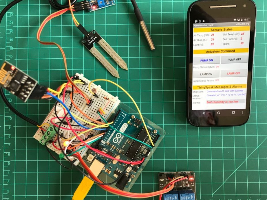
9 android app - part one
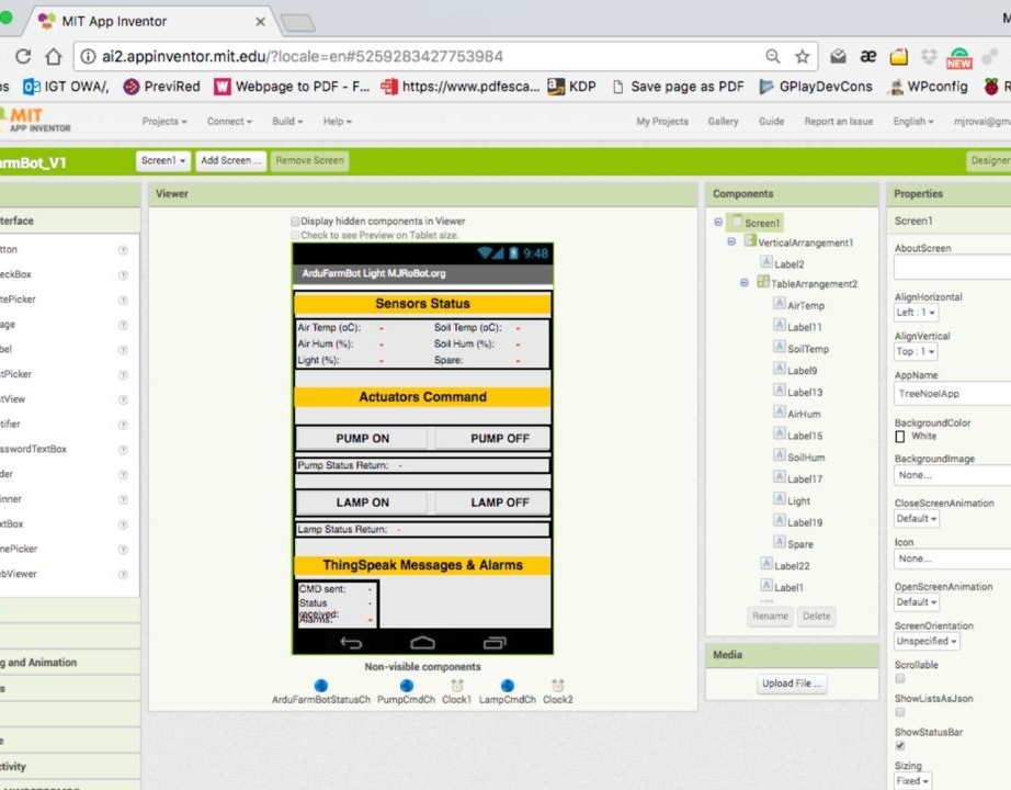
First you need to create a user interface. The picture shows the main visible and invisible elements.
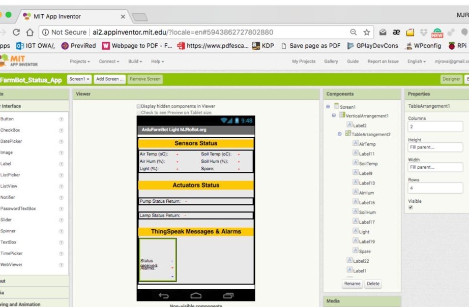
After that, you need to create blocks. Menu items correspond to screenshot numbers.
1 State variables that should be declared as global
2 Every two seconds (depending on Clock1) a procedure is called "readArduino"
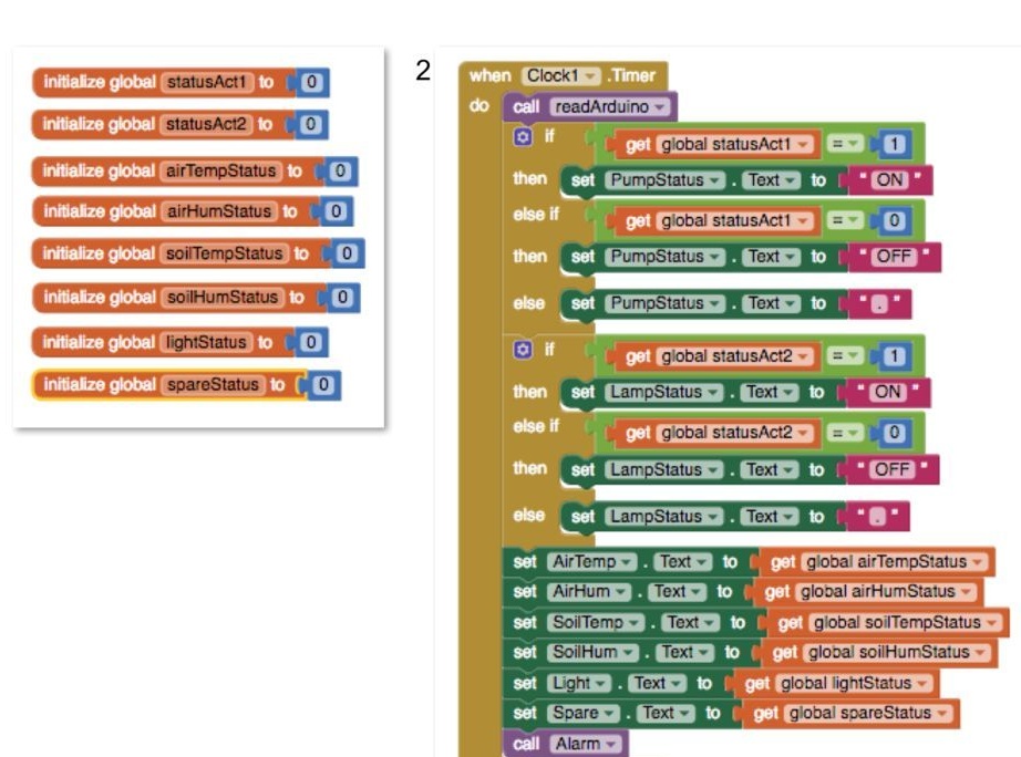
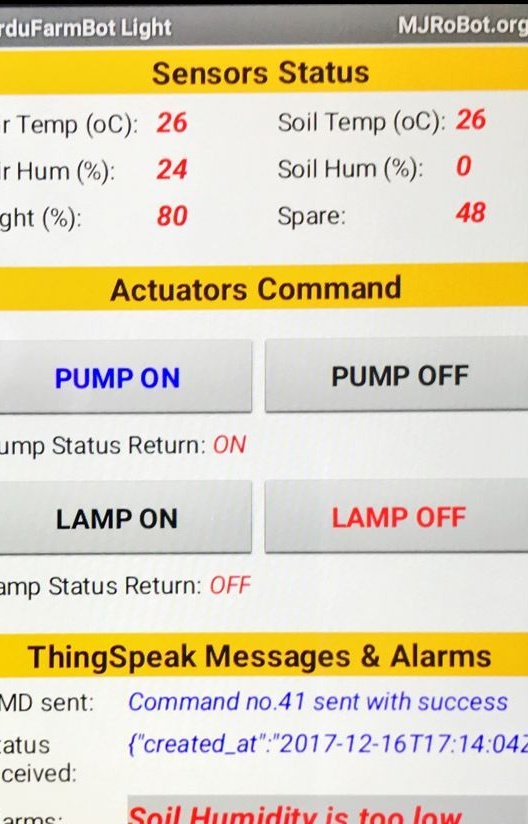
The procedure returns the value of the variables that should be displayed on the screen. In this case, the state value (0 and 1) for the actuators are converted to “ON” and “OFF” for better perception.
These values (Status) will be displayed in the corresponding “Shortcuts”
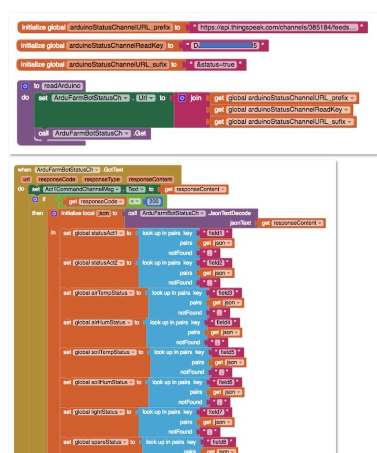
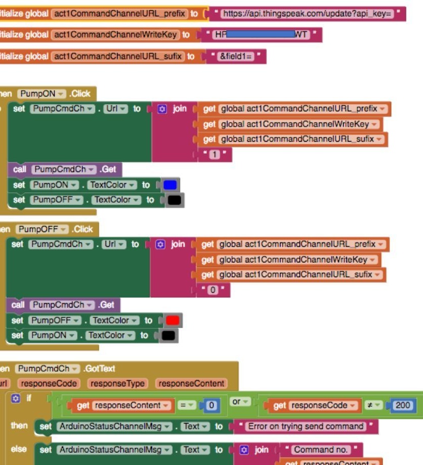
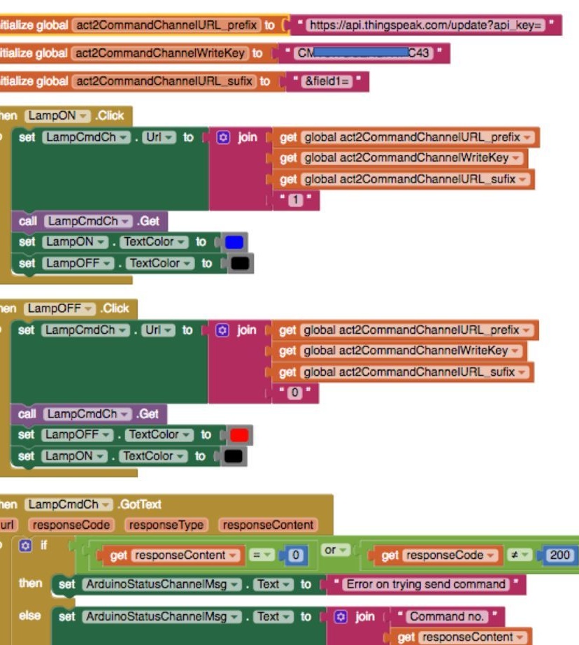
3 The readArduino routine will essentially read the status channel in ThingSpeak. So, you need to determine the URL that will be sent to Thingspeak. To do this, 3 global variables must be declared and combined to create the URL that will be sent to ThingSpeak. GET should be sent to a web component called "ArduFarmBotStatusCh"
4 Text received from the previous command will arrive in JSon format. This text needs to be processed so that each field is read and stored in the corresponding global variable.
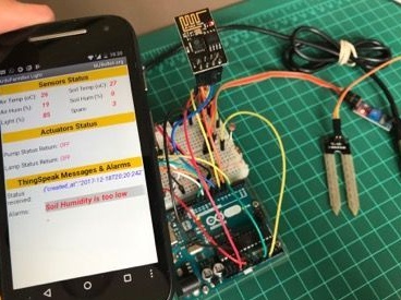
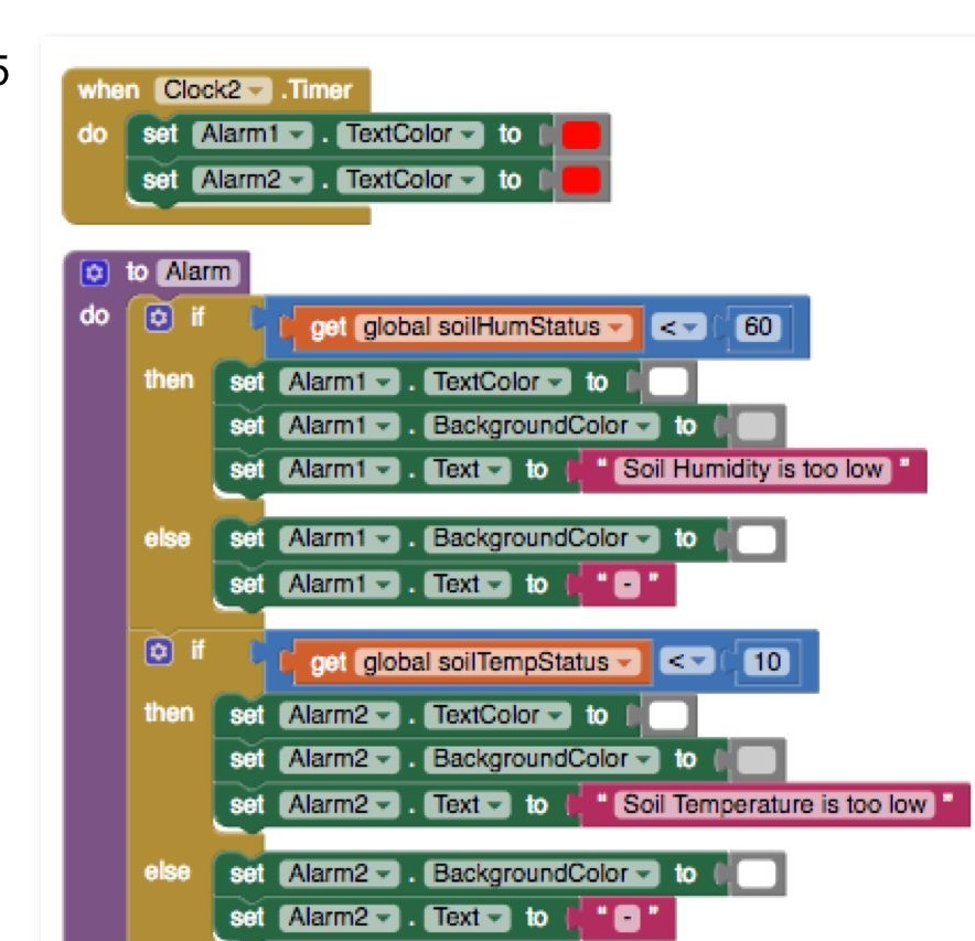
5 The last thing to do is to call the “Alarm” procedure, which will analyze the state of two soil sensors. If the temperature is too low (in our case 10oC), a message should be displayed. The same for moisture if it is below 60%.
Please note that we have defined another timer (Clock2), programmed to have it run every second. It is only needed to "switch" the color of the message text (from white to red). The message will blink.
Application code can be downloaded at
10 Connection of actuators
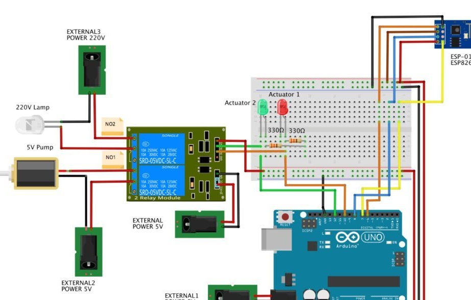
Commands for turning the pump and lamp on and off will be received remotely. Ardunio's output will activate the relay and LED, taking these commands. The picture shows how the actuators should be connected. Please note that GND relay output NOT CONNECTED to GND outputUNO. This way there will be less power interference when the relay is running.
11 configuration of the channel actuators (Actuators Channels)
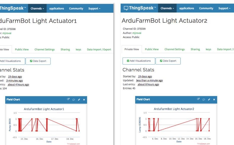
All actions repeat the procedure for configuring the Status channel. It is necessary to create two channels for each of the devices. For each channel, write the Channel ID, Read and Write keys. We will write only in the first field of each channel. For example:
Channel ID 375598 ==> LED Red (Pump)
◦ Field1 = 0 ==> Pump OFF
◦ Field1 = 1 ==> Pump ON
2. Channel ID 375599 ==> LED Green (Lamp)
◦ Field1 = 0 ==> Lamp OFF
◦ Field1 = 1 ==> Lamp ON
11 loading and testing code actuators in Ardunio.
When we sent data to the cloud, we “wrote” this data to the ThingSpeak. Status channel, “transmitting” (uploading) this data. Now we have to “read” the data from the Actuator Channel, “accepting” (downloading) this data.
To do this, send a GET string and this procedure consists of 3 stages.
"Start cmd"
AT + CIPSTART = "TCP", "184.106.153.149", 80Line length
AT + CIPSEND = 36And the GET string itself
GET / channels / 375598 / fields / 1 / lastChannels will be “read” every 10 seconds
After sending the GET, we must accept the response from ThingSpeak. The answer must be either 0 or 1, for each channel. If there are any other values, then we simply ignore them.
The main difference between this part and the previous one is only in the function readThingSpeak (String channelID)
Below is the code that performs the described actions.
// Thingspeak
String canalID1 = "999999"; // Actuator1
String canalID2 = "999999"; // Actuator2

#include
SoftwareSerial EspSerial (6, 7); // Rx, Tx
#define HARDWARE_RESET 8

// Variables to be used with timers
long readTimingSeconds = 10; // ==> Define Sample time in seconds to receive data
long startReadTiming = 0;
long elapsedReadTime = 0;

// Relays
#define ACTUATOR1 10 // RED LED ==> Pump
#define ACTUATOR2 12 // GREEN LED ==> Lamp
boolean pump = 0;
boolean lamp = 0;

int spare = 0;
boolean error;

void setup ()
{
  Serial.begin (9600);

  pinMode (ACTUATOR1, OUTPUT);
  pinMode (ACTUATOR2, OUTPUT);
  pinMode (HARDWARE_RESET, OUTPUT);

  digitalWrite (ACTUATOR1, HIGH); // o módulo relé é ativo em LOW
  digitalWrite (ACTUATOR2, HIGH); // o módulo relé é ativo em LOW
  digitalWrite (HARDWARE_RESET, HIGH);

  EspSerial.begin (9600); // Comunicacao com Modulo WiFi
  EspHardwareReset (); // Reset do Modulo WiFi
  startReadTiming = millis (); // starting the "program clock"
}

void loop ()
{
  start: // label
  error = 0;

  elapsedReadTime = millis () - startReadTiming;

  if (elapsedReadTime> (readTimingSeconds * 1000))
  {
    int command = readThingSpeak (canalID1);
    if (command! = 9) pump = command;
    delay (5000);
    command = readThingSpeak (canalID2);
    if (command! = 9) lamp = command;
    takeActions ();
    startReadTiming = millis ();
  }

  if (error == 1) // Resend if transmission is not completed
  {
    Serial.println ("<<<< ERROR >>>>");
    delay (2000);
    goto start; // go to label "start"
  }
}

/ ********* Take actions based on ThingSpeak Commands ************* /
void takeActions (void)
{
  Serial.print ("Pump:");
  Serial.println (pump);
  Serial.print ("Lamp:");
  Serial.println (lamp);
  if (pump == 1) digitalWrite (ACTUATOR1, LOW);
  else digitalWrite (ACTUATOR1, HIGH);
  if (lamp == 1) digitalWrite (ACTUATOR2, LOW);
  else digitalWrite (ACTUATOR2, HIGH);
}

/ ********* Read Actuators command from ThingSpeak ************* /
int readThingSpeak (String channelID)
{
  startThingSpeakCmd ();
  int command;
  // preparacao da string GET
  String getStr = "GET / channels /";
  getStr + = channelID;
  getStr + = "/ fields / 1 / last";
  getStr + = "\ r \ n";

  String messageDown = sendThingSpeakGetCmd (getStr);
  if (messageDown [5] == 49)
  {
    command = messageDown [7] -48;
    Serial.print ("Command received:");
    Serial.println (command);
  }
  else command = 9;
  return command;
}

/ ********* Reset ESP ************* /
void EspHardwareReset (void)
{
  Serial.println ("Reseting .......");
  digitalWrite (HARDWARE_RESET, LOW);
  delay (500);
  digitalWrite (HARDWARE_RESET, HIGH);
  delay (8000); // Tempo necessário para começar a ler
  Serial.println ("RESET");
}

/ ********* Start communication with ThingSpeak ************* /
void startThingSpeakCmd (void)
{
  EspSerial.flush (); // limpa o buffer antes de começar a gravar

  String cmd = "AT + CIPSTART = \" TCP \ ", \" ";
  cmd + = "184.106.153.149"; // Endereco IP de api.thingspeak.com
  cmd + = "\", 80 ";
  EspSerial.println (cmd);
  Serial.print ("enviado ==> Start cmd:");
  Serial.println (cmd);

  if (EspSerial.find ("Error"))
  {
    Serial.println ("AT + CIPSTART error");
    return
  }
}

/ ********* send a GET cmd to ThingSpeak ************* /
String sendThingSpeakGetCmd (String getStr)
{
  String cmd = "AT + CIPSEND =";
  cmd + = String (getStr.length ());
  EspSerial.println (cmd);
  Serial.print ("enviado ==> lenght cmd:");
  Serial.println (cmd);

  if (EspSerial.find ((char *) ">"))
  {
    EspSerial.print (getStr);
    Serial.print ("enviado ==> getStr:");
    Serial.println (getStr);
    delay (500); // tempo para processar o GET, sem este delay apresenta busy no próximo comando

    String messageBody = "";
    while (EspSerial.available ())
    {
      String line = EspSerial.readStringUntil ('\ n');
      if (line.length () == 1)
      {// actual content starts after empty line (that has length 1)
        messageBody = EspSerial.readStringUntil ('\ n');
      }
    }
    Serial.print ("MessageBody received:");
    Serial.println (messageBody);
    return messageBody;
  }
  else
  {
    EspSerial.println ("AT + CIPCLOSE"); // alert user
    Serial.println ("ESP8266 CIPSEND ERROR: RESENDING"); // Resend ...
    spare = spare + 1;
    error = 1;
    return "error";
  }
}
You can download it at
12 sending commands to devices
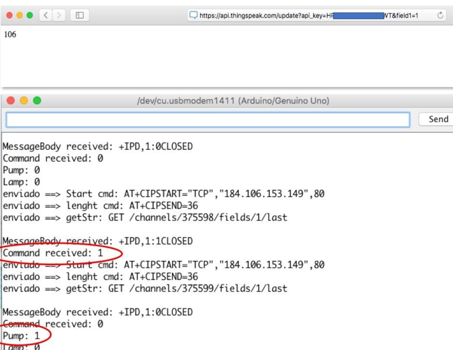
At this stage, we have a configured actuator channel changing the value of field 1 for each device. We must verify that the devices work out the commands properly. At the end of the project, an android application will be used for this, but it can also be done through a browser.
Turn on the pump (red LED on)
https://api.thingspeak.com/update?api_key=Saved_channel_key_1&field1=1Pump off (red LED off)
https://api.thingspeak.com/update?api_key=Saved Channel_key_1&field1=0Turn on the lamp (green LED is on)
https://api.thingspeak.com/update?api_key=Saved Channel_key_2&field1=1Turn off the lamp (green LED off)
https://api.thingspeak.com/update?api_key=Saved Channel_key_2&field1=014 Ending the android program
In the previous part, there was a simple program that “read” the data from the channel and displayed it on the screen. Now we need to make the program “write” the commands in Actuator Channal, so that these commands can be read by the controller and the lamp with the pump worked accordingly.
So that the user can send commands, the application will have two buttons for each device. If turned on, blue; if turned off, red.
By clicking the buttons in the application, you can see the result in the Serial Monitor.
The code can be downloaded at
15 Final assembly
At this stage, there is a fully completed android application, a fully assembled hardware part, but there is no code in the controller that would constantly read the data and send commands to the cloud. You just need to combine all the fragments of the code written earlier. Of course, the code has additional verification options (for example, if ESP-01 freezes). To do this, periodically, before each read or write command, an AT command is sent.And if the answer OK did not come from the module, then the module is forcibly rebooted software.
The full project code can be downloaded at
At the address you can get updates for program files.
You can also read comments on the link to the source, if something is not clear.