

The circuit of this amplifier was developed by wonderful audio designers Alexander Bokarev and Alexander Rezvoy. Generally speaking, this is a family of amplifiers in different versions, in which different lamps work - 6S15P, 6S45P, 6E5P their combinations and in different ways, the bias of the amplification lamp is organized, which affects the color of the sound. The amplifier is single-stage, single-cycle, with an output power of 1 ... 3 W, depending on the load resistance.
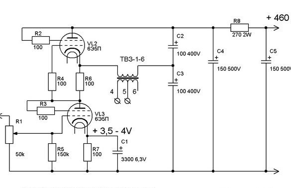
The amplifier circuit is very simple, but somewhat unusual. Mentioned SRPP is an English abbreviation, and in normal language it is called an amplifier stage with active or dynamic load or a cascode. This circuit has quite a few advantages and it will be applied, most often not in the output stages of sound amplifiers, but I got here too. Here, its primary advantage in comparison with the classical single-stage cascade is the absence of direct current flowing through the output transformer. This allows you to do the latter without a non-magnetic gap, which significantly increases the inductance of the primary winding and does not allow the "response" of the frequency response at low frequencies. So, there will be bass. In general, in this scheme, the requirements for the main element - the output transformer, are very facilitated. That's good.
In the tube circuits of sound amplifiers, there is another section, the construction of which introduces a noticeable color of sound - the offset of the amplifier stage. In the diagram above, it is organized by a resistor R7, a shunted electrolytic capacitor, and is called "automatic." That is, the desired voltage is obtained when the anode current passes through the resistance of the resistor. Experimentally, it was found that amplification cascades in the cathodes of which there is no resistor (or a zener diode is another way) sound best. This allows you to make a "fixed" offset - the supply of negative voltage to the lamp grid. In powerful amplification lamps, where this voltage reaches more than one dozen volts, it is supplied from a separate rectifier, here, you can use a galvanic cell. By experiments, it was found that this method is preferable in the sense of sounding an amplifier.
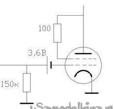
A fragment of an amplifier stage circuit with a battery bias. A 3.6 V lithium battery is available.Moreover, there are options with long wire leads for soldering, which greatly simplifies the matter - elements like clockwork are soldered poorly, with a risk for their capacity or overall performance, and few people have low-power contact welding.
A cascade with bias by a galvanic cell, subjectively, sounds very good and simplifies the circuit. Due to the high load resistance, its discharge current is negligible and even the clock element lasts for many years. However, it is necessary to periodically check its condition - with a decrease in the bias voltage (discharge of the element), the anode current of the lamp increases and, ultimately, goes beyond the permissible limit - the lamp fails.
There are various control methods, the simplest of which is to periodically check the voltage with a “tester”. A reliable and simple way to indicate the discharge of an element is to connect in series, in the anode circuit, an LED shunted by a resistor. The resistor is selected so that with an increase in the anode current of the lamp (discharge of the element in the bias circuit), a voltage drop formed on it sufficient for the LED to glow.
What was used at work.
Tools, equipment.
In the manufacture of the amplifier case, a circular saw, an electric drill, and a surface grinder were used. A set of ordinary hand tools - screwdrivers, pliers, files. A hacksaw for metal came in handy. To drill holes in the circuit board, a drill of small holes was required - 1 ... 1.5 mm. For electrical installation - a set of appropriate tools, a soldering iron is understandable, and preferably two - medium and larger, belonging to them. For varnishing - dishes, brushes, rags. Hot melt glue gun, dishes for preparing a compound for pouring. A multimeter, better two. Construction or special hair dryer for working with heat pipes.
Materials
In addition to radioelements, I needed thick plywood for the case, thin for the cases of capacitors, paintwork materials, insulation tape, a narrow paper tape, a winding wire. A piece of foil fiberglass, the same piece of aluminum 3 ... 5mm thick. Hook-up wire, fixture, thermotube. Solder (used lead-free - tin-silver-copper), flux to it. Nylon ties.
So, despite the fact that the amplifier is described here, it all started with the assembly of the layout of the power supply - a high-voltage rectifier-stabilizer on a field-effect transistor, glow stabilizers.
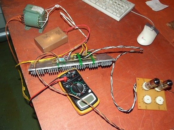
Here, checking the performance of the stabilizers, checking the needle radiator - does it cope with heat recovery. Since the amplifier works in the “A” mode, the quiescent current is constant and does not depend on the output power - to check the power supply, it is enough to simulate the corresponding resistance, it is glowing and it is there, it does not work anyway or not.
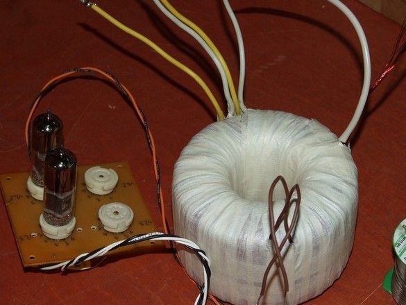
The output transformer, of course, can be smaller, but to walk like that for a walk - a slightly redone network transformer was used, on the toroidal ring magnetic core, with an overall power of 400W. Here, in contrast to the classical output transformers, the requirements are significantly lower - minimum sectioning - half of the secondary winding-primary-second half of the secondary. This is if you connect the secondary windings in series.
The required transformation ratio is 20 ... 22.
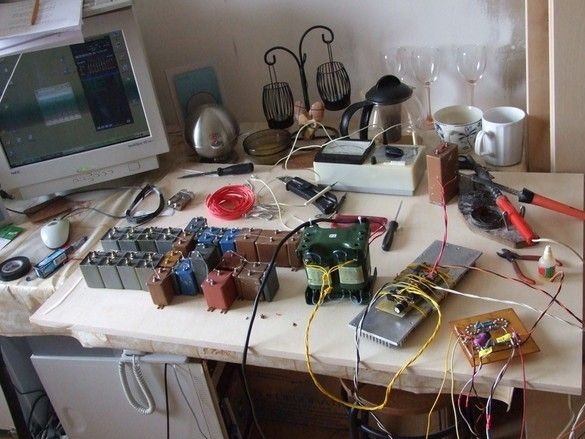
The layout of one amplifier channel, the capacitors are a battery, composed of capacitors with paper and paper-oil dielectric, it is customary to think that their use is very beneficial for the sound of a tube amplifier. Their bag, obtained by a large number of flights to the flea market, is sorted and selected fighters suitable for voltage. The latter are divided into four equal parts.
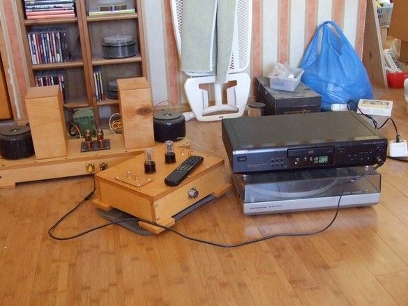
The amplifier layout is mounted in a hinged manner on a piece of thick plywood so that the structure can be transferred from the table to speaker system for listening, it’s curious what happened there.
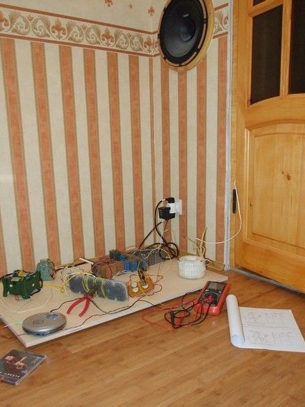
But it turned out very good, but in the finished design it will be even better - the extra wires will leave, the connections will be shortened.
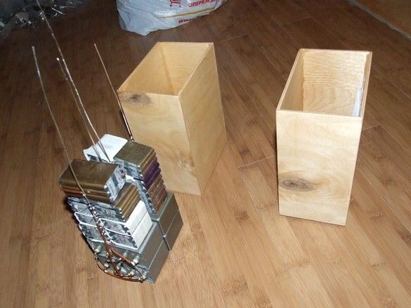
A huge capacitor bank, of course, was cultivated. Two in a separate box - to optimize the layout of the amplifier. In general, in this design, a strong-willed decision was made to pay maximum attention to sound quality, the rest is mass, dimensions, output power - secondarily. Hence the single-stage design - less distortion, huge output transformers and paper capacitor batteries.
Yes, capacitors. Separate capacitors were carefully removed from the tin cases, had to tinker with a hacksaw for metal, and molded into compact batteries, two batteries isolated from each other, with a capacity of about 100 microfarads, for a voltage of at least 500 V. “Stripping” of paper capacitors, according to colleagues, favorably affects the sound, well, and significantly reduces the dimensions of the battery of course. The lower capacitors of the battery are oil-filled and I did not begin to remove the casing from them. The bushings are made of thick tinned copper wire.
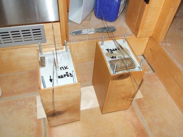
The walls of the boxes for capacitor banks are cut out of thin plywood, after varnishing, the boxes are glued with hot glue, the batteries themselves are placed in them and filled with epoxy mixed with dry, sifted sand. In the corners of the boxes, before pouring, segments of the M6 stud with a nut and a reinforced washer are inserted to make it harder to pull out.
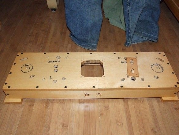
The case of the lamp circuits is quite peculiar and is due to the mass and location of the terminals for a fairly large number of "installation" radio elements - electrolytic capacitors for high operating voltages, transformers, chokes, lamp panels. These elements are mechanically attached, often have short hard leads on the one hand, perfectly fulfilling the role of contact petals for smaller elements. Large elements are mounted on the chassis with a small "basement", where conclusions are issued. In the basement of the chassis, as a rule, the entire installation is carried out by a mounted method.
On the “case” lies a plywood plate for installing power connectors - one for connecting the filament voltage of the lamps, the second for the anode voltage. Initially, he planned to use DB-9, such as those used for COM ports of the computer system unit and the socket for them, having thought, strengthened this place by 2RMG.
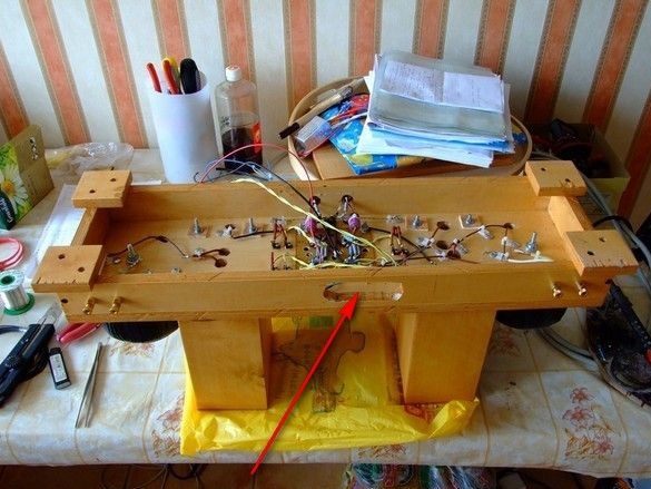
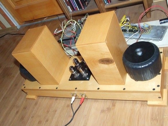
The protruding boxes of capacitor banks serve as an excellent stand for the amplifier in an inverted, “mounting” state, which is very convenient when setting up and finalizing, you do not need to pull out the lamps from the panels, you can turn them on along with them, measure the necessary parameters. It remains only to install the power connectors. So far, the amplifier has worked by passing the power wires through the connector holes.
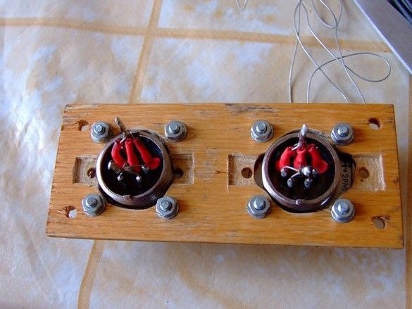
Two brothers acrobat. 2RMG, sealed, not khukh-mukhra, the amplifier can now be turned on under water. One for glow, the second for anode voltage.
Ready-made amplifier, rear layout of the power supply, it will be in a separate case.
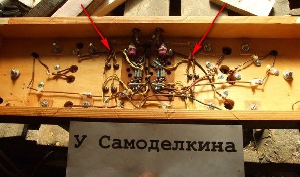
Installation view, elements not shown in the diagram - two 100 Ohm resistors each, for each pair of lamps - an artificial mid-point of light - greatly reduces the background.
A selection of amplifier circuits of a similar topology:
View online file: