

A preamp-corrector, or an amplifier-corrector, or a photocorrector - specialized electronic an amplifier for the mechanical recording reproduction path, which restores the initial spectrum of the sound signal recorded on the plate and amplifies the output voltage of the pickup head to a typical level of linear output — from 0.775 V (0 dBu) in household analog equipment to 2 V (8 dBu) in digital and broadcast equipment.
I will explain about the “restoring initial spectrum”. The fact is that the system of mechanical recording of sound - a cutter on the varnish film of a metal disk, has several hardly removable resonances, two of which are within the frequency range reproduced by conventional equipment for wide use. We are talking about frequencies of 500 and 2120 Hz (they correspond to time constants 3180 and 318 μs.). The easiest way to deal with them (resonances) was to cut out frequency sections, with their restoration in the playback device using special “corrective” circuits. That's why the "corrector".
Devices for high-quality reproduction of a recording, rather complex and capricious devices - common "high-voltage" heads with a movable magnet, provide a signal amplitude of 5 mV at a frequency of 1 kHz, which will have to be amplified to 0.15 ... 2 V, without allowing self-excitation in amplification stages. In addition, when working with such small signals, the problem of the “microphone effect” arises in full growth, especially in the case of the use of electron-vacuum devices. There is also another difficulty - noise and interference. Under the same conditions - vacuum devices, a large gain, low input voltages comparable to microphone ones. In part, the problem can be solved by choosing the electrical modes of the cascades, partly by constructive measures. The design of the amplifier-corrector in a wooden open case, including without shielding the lamps, allows you to make sure that the "electrical" measures were quite complete - you can hear the noise only by putting your ear into the speaker system.
The initial circuit of the amplifier-corrector "Gus-Khrustalny" was developed by whoever you think would be "Odessa laboratory assistants" Yevgeny Babichenko and Igor Gaponov [1] and implemented on 6G2.The choice of components and modes of the circuit described in the previous parts, I recommend that you familiarize yourself with them, at the same time taste Odessa humor, mathematical and electrical calculations in the language of Isaac Babel and Mikhail Zhvanetsky, this is something. You will laugh like that - I envy you.
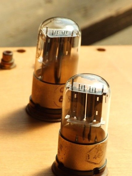
There is also work [2], where this vinyl corrector, with the participation of the authors, was converted to 6H9 lamps - similar triodes, only two pieces in one glass bottle, (6G2 in iron). The same high internal resistance and high gain, why not?
Schematic diagram of the "Goose-Crystal" on 6N9S, thanks to Vladimir Semin. From the author’s scheme, my performance is distinguished by the absence of the “traditional” part of the correction chain - not for experiments, but for music. In addition, a kenotron rectifier with a choke is replaced by a diode bridge with a stabilizer on a high-voltage field effect transistor. The power supply is made in a separate remote unit and will be considered separately.
The absence of switching significantly simplifies the circuit - a switch in the signal circuit is excluded, which should have been of fair quality or a set of relays in a sealed enclosure with good contacts that allow switching of very small signals. In addition, a part of the “exact” elements is omitted - in the correction circuits, there must be components that do not correspond to the standard series, which must be selected with high accuracy, which usually presents some difficulty.
What was used in the work.
Tools, devices, equipment.
A set of tools for electrical installation. Small power soldering iron - 25 ... 40W, for conventional installation, soldering iron 65 ... 100W, for mounting massive leads, bundles of wires, tires. Accessories for soldering irons. A multimeter, and preferably two with accessories. I used the simplest oscilloscope, but you can do it. To accurately measure the resistance and capacitance of the frequency-setting elements, access to an E7-type measuring bridge was required. To select the “correction for the natural inductance of the head” elements, see [1], you need an audio range signal generator, an alternating current voltmeter (millivoltmeter). A set of small bench and carpentry tools. To cut the blanks of the body from thick plywood, I used a small home-made circular saw. An electric drill with drills came in handy, but an electric drill, a jigsaw. Hot melt glue gun. A building or special hairdryer for working with thermotubes.
Materials
In addition to radioelements, I needed a piece of non-thin plywood for the case. Forster drill. Hook-up wire, large cross-sectional wire with a single conductor, for “common wire”. Contact pads, nylon ties. Hot melt adhesive, silicone and acrylic sealant, sticky paper tape, thermotubes. Adhesive insulating tape, perforated steel tape for fastening large elements. Permanent marker for "technological" signatures. Epoxy adhesive. Lead-free solder, low-temperature "indium" solder for soldering the findings to the "clock" galvanic cells. For the “stand” of the selection of elements for “correction on the natural inductance of the head” see [1], a piece of the circuit board came in handy.
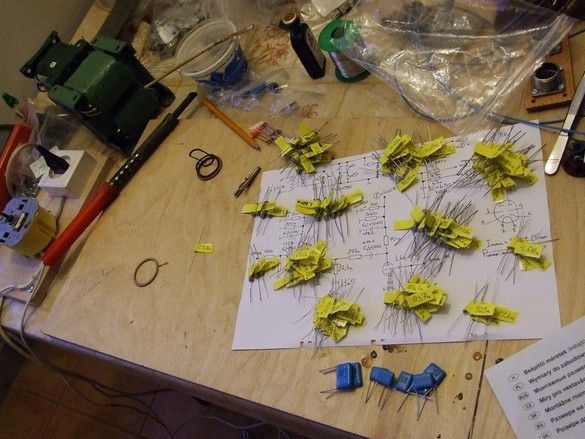
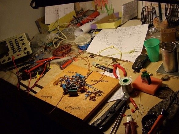
"Accurate" radioelements from the correction circuits, bought several dozen close denominations from the standard range of 10% accuracy. I sat down at the measuring bridge and re-measured them, inscribing the exact denomination to the third decimal place, on sticky labels. Then, picked up the nearest ones, it was more convenient to make some denominations of two.
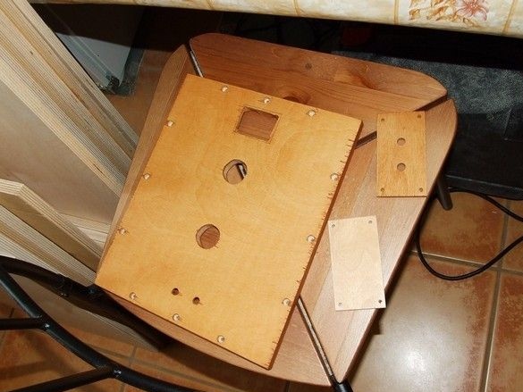
The upper panel of the body is the chassis. On it, in fact, the entire installation. Sawed from a thick - 15mm plywood. I drilled holes for mounting elements and fasteners. I drilled holes for lamp panels for octal base with a feather drill on wood, for signal sockets, with an ordinary spiral drill, having previously reduced the panel thickness with a Forster drill. The rectangular opening is the result of some kind of error, I decided not to redo the panel, but to close it with a thin plywood cover, it’s not bad - you can immediately see where the entrance is and where the exit is.
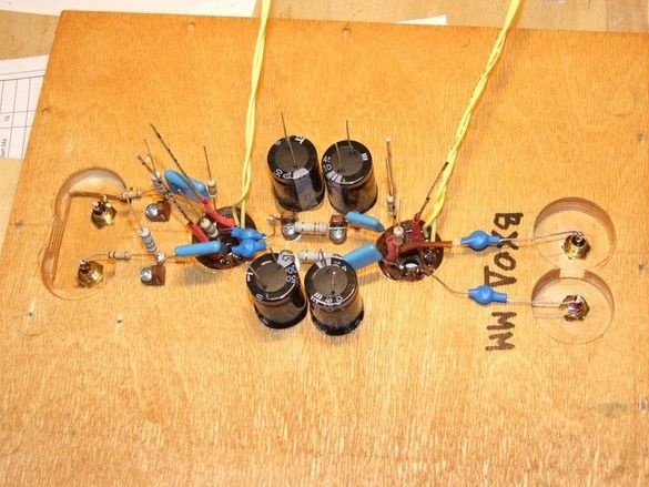
For cylinders of electrolytic capacitors, I drilled blind holes to ¾ depth, pasted the capacitors with hot-melt adhesive, orienting them so that the leads went to the connection point along the shortest path. Tube panels were glued with epoxy glue, previously, having carefully cleaned the glued surfaces with a rough skin. Above the inscription in the blue thermotube are the clock batteries displacing the input stages. If you search, you can find the second pair. Yellow twisted wires - glow. Additional points for installation are organized by special mounting tabs in the insulator with a hole.
The next level of installation is the “common wire” bus, power conductors, and other elements. Installation is made mainly by its own findings of the elements. The only drawback of this design is maintainability, which, frankly, is not up to par. You can get to the batteries completely. However, this is generally characteristic of volumetric installation.
It was interesting to listen as soon as possible - what happened. After the main part of the installation, the panel is "put" on two suitable boards, so as not to damage the installation, with an anode voltage and filament stabilizer, connected "on a live thread".
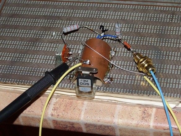
"Stand" for the selection of the values of the elements of the circuit "input correction for the natural inductance of the pickup head" [1]. From a piece of thin foil plastic, a pickup screen is organized.
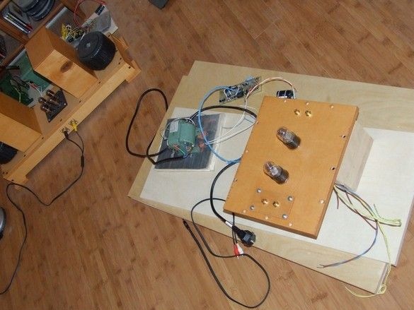
Design refinement - blocking paper containers at the corners, case, “legs” with vibration isolation from a thick layer of soft silicone sealant. 2RMG power connector, grounded “artificial midpoint” of 100 Ohm resistors powered by heat. The terminal of the "common wire", without fail. Without connecting it to a colleague on the player, a strong background. Heavy capacitors blotted onto acrylic sealant and secured by pieces of galvanized perforated tape.
In general, I liked the vinyl corrector. The disadvantages include the relatively low gain and the need for a rather dreary procedure for selecting a resistor to a specific pickup instance. On the other hand, we change the pickups not so often and it is quite possible to tolerate. The lack of gain is primarily due to the relatively low sensitivity of my single stage power amplifier. The sound quality is fully satisfied - the records through it play perfectly.
Used Books.
1. RIAA amplifiers - corrections on vacuum triodes for “high-speed” (electrodynamic) pickups. Evgeny Babichenko,
Igor Gaponov. 2004 (Part 1 ... 6).
2. The preamplifier-corrector RIAA "Goose-Crystal". Vladimir Semin 2004