» Electronics » Arduino »Laser engraver from DVD version 2.0

Laser engraver from DVD version 2.0

Laser engraver from DVD version 2.0

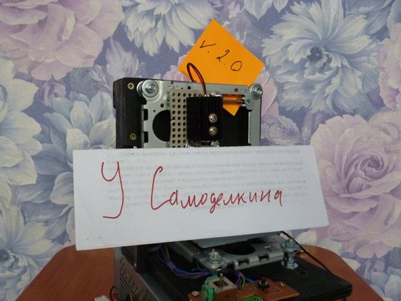
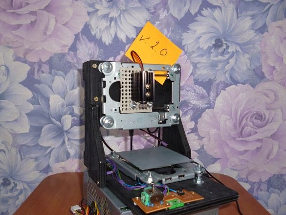
Hello again. Not so long ago, I laid out instructions for creating a laser engraver from a CD or DVD-rom. The first version of the laser engraver was completely working, but not without a number of problems. Firstly, I used the L9110S engine driver, thereby losing the ability to use the microstep of the engine, and as a result, the resolution of the engraving was limited. There was also a problem with the incompatibility of the engraver software with standard engraver programs. In the second version, I removed all the flaws, and the engraver began to meet the standards and also obey G-codes. The basis has remained the same; the electrics and software have changed. And I present you with instructions for refitting the previous one or creating a new laser engraver.

We have to:

- DVD-ROM or CD-ROM
- Plywood 10 mm thick (6 mm can also be used)
- Wood screws 2.5 x 25 mm, 2.5 x 10 mm
- Arduino Uno (compatible boards can be used)
- Arduino CNC Shield v3
- Laser 1000mW 405nm Blueviolet
- A4988 stepper motor drivers with radiators 2 pcs.
- 5V power supply (I will use an old, but working computer power supply)
- Transistor TIP120 or TIP122
- Resistor 2.2 kOhm, 0.25 W
- connecting wires
- Connector 2.54 mm Dupont
- Eletrolobzik
- drill
- Drills for wood 2mm, 3mm, 4mm
- Screw 4 mm x 20 mm
- Nuts and washers 4 mm
- soldering iron
- Solder, rosin

Step 1 We assemble the case, mechanics and prepare the power supply.
Here we do everything exactly as in the first, second and third steps of the instruction "Laser engraver from old DVD-Rom".

The fourth step can be omitted, since we do not need a joystick. We will send all commands through the terminal.

Step 2 Preparing the engines.
About how to remove stepper motors and carriages you read in the first article. So, as there we solder the wires to the engines. Dupon connectors must be riveted at the other end of the wires:


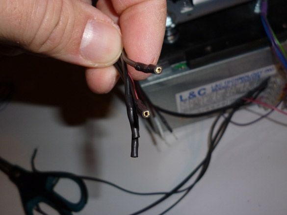
If there is, it is convenient to use a plastic case for them, on four wires. If not, you can, like me, just put a heat shrink on each of the wires.

Step 3 We collect the electrician.
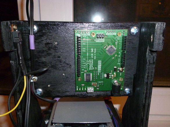
The brain of our engraver is Arduino Uno.


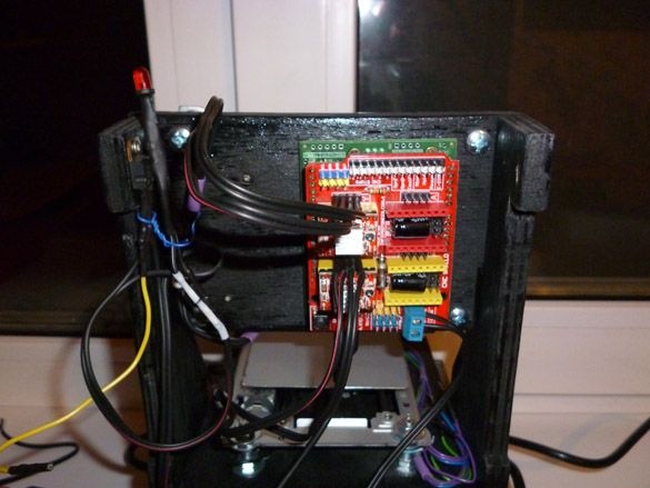
Install it in the back of the engraver:


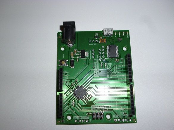
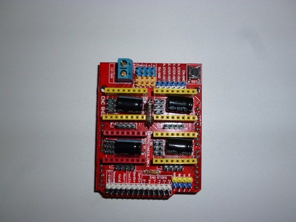
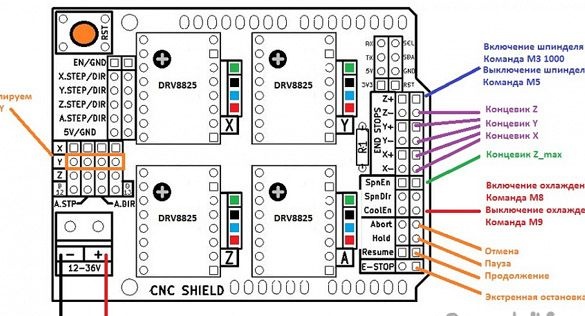
One of the most important parts is the Arduino CNC Shield. We will use the third version of this expansion card. Thanks to her, we will significantly reduce the number of wires and simplify the assembly of the engraver:


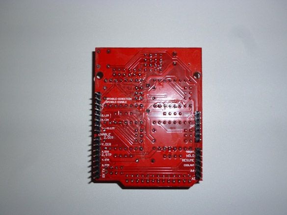
And on the flip side:


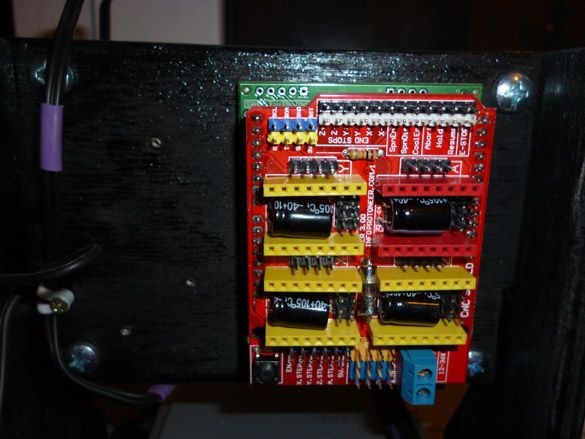
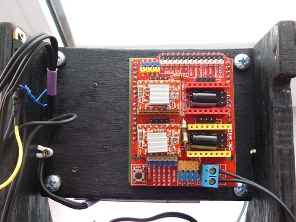
We put Arduino CNC Shied v3 on top of Uno:


Jumpers should be included with the expansion board. Before installing the driver, you must install jumpers on the X and Y axes. Namely, jumpers MS0, MS1 and MS2 must be installed on the X and Y axes.Thus, we will set the microstep to 1 \ 16. If you get confused a little instruction on this expansion board:
cnc_shield_v3.pdf [983.79 Kb] (downloads: 1541)
View online file:


Dravers look like this:


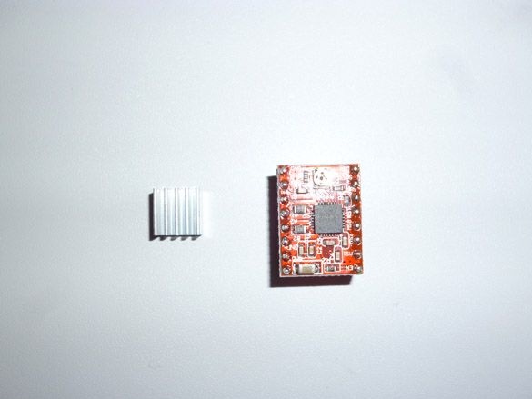
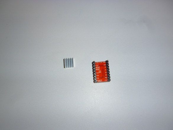
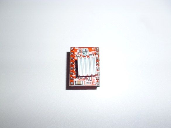
First, install the radiators on the driver:


And then we put them in place for the X and Y axes. Pay attention to the position of the driver. Since it can be easily installed is not true. The EN key on the driver must match the same socket on the expansion board:


I recommend buying immediately a kit consisting of Arduino Uno, CNC Shield and A4988 drivers with radiators. This is cheaper and you don’t have to wait until the next component comes up.

The finished laser we bought with a driver and a cooling radiator consumes up to 500 mA. It cannot be directly connected to the Arduino. To solve this problem, take a TIP120 or TIP122 transistor. The 2.2 kOm resistor is included in the gap between the Base of the transistor and pin 11 of the Arduino. On the CNC Shield, this pin is designated as Z +. This is not a typo. Here's the thing. Looking ahead, I’ll say that we will work with the GBRL 1.1 firmware. CNC Shield v3 was made for an earlier version of this firmware. In version GBRL 1.1, the developers decided to redo the port numbering, and therefore it differs from what is written on the board. Namely, they interchanged Z + (D12) and Spn_EN (D11). The spindle is connected to D11, which is a PWM port, for controlling the engine speed, or laser power in our case. Image with modified pins:


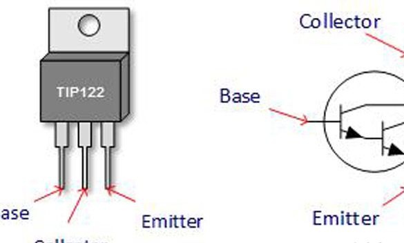
Base - R 2.2 kOm - pin 11 Arduino (Z + CNC Sheild)
Collector - GND Laser (Black Wire)
Emitter - GND (Common Power Supply)
+5 laser (red wire) - +5 power supply

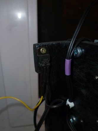
The circuit is not complicated, so we solder everything in weight, insulating the wires and legs of the transistor, broadcasting it to the back, on the side


Setting up GBRL firmware is not an easy task, especially for a beginner. And with a laser, like matches, children are not toys. Even with a reflected beam, the eye can be seriously damaged. Therefore, I recommend working with the laser only in goggles, and for the time of tests and settings, connect a regular LED instead of the laser. Color does not matter. Having included a suitable resistor in the gap of the positive wire of the diode, we connect an LED instead of a laser:


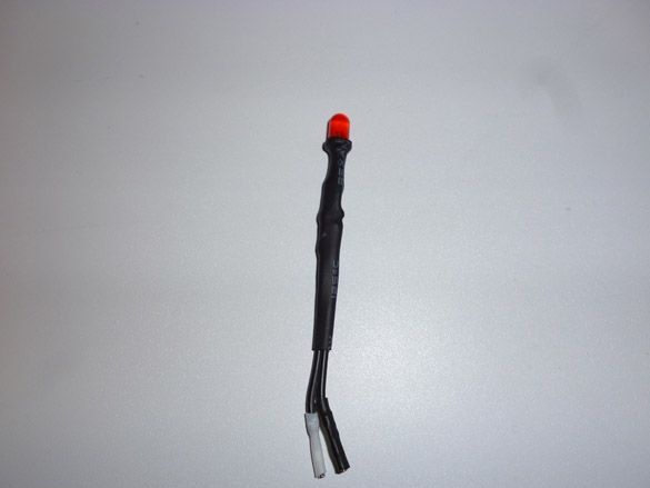
Safety glasses and a test diode will minimize incidental problems with the engraver.


Step 4 Setting the motor current limit.
Setting the current strength is necessary to reduce noise when operating at high currents, to get rid of shear at low currents, and also to reduce the heating of the stepper motor.

We connect the negative wire of the multimeter to the GND contact, and press the positive wire to the body of the tuning resistor on the driver. Twist the tuning resistor with a small screwdriver, measuring the voltage Vref. Thus, we set the correct current for our stepper motor driver.
The Vref formula for the A4988 depends on the value of the resistors installed on them. This is usually an R100.

Vref = Imax * 8 * (RS)

Imax - current of the stepper motor
RS is the resistance of the resistor.
In our case:
RS = 0.100.
The recommended current strength of the stepper motors is 0.36A. But I prefer to increase it a little.
Imax = 0.4
Vref = 0.5 * 8 * 0.100 = 0.32 V.

Step 5 Fill GBRL 1.1.
It is most convenient to write a ready-made HEX firmware file to Arduino Uno.
grbl-1_1f_20170801.zip [296.07 Kb] (downloads: 1066)


To do this, you need the XLoader program:
xloader.zip [646.9 Kb] (downloads: 789)


Run the program. Select the previously downloaded HEX file. Below, we select our controller from the list, namely Uno (ATmega328). Next, select the com port to which Arduino is connected. We set the speed to 115200 and click Upload. After waiting for the completion of the fill, you can proceed to the verification and configuration.

Step 6 Settings.
The parameters included in the firmware differ from the parameters of our machine. The terminal window is used for configuration. You can use any that you like. I prefer the Arduino IDE. Download it from the official site of the project:

https://www.arduino.cc/en/Main/Software

No libraries are required, we only need a terminal from the Arduino IDE. In the Tools tab, select our board - Arduino Uno, then select the com port to which it is connected. After that, launch the terminal located in the Tools - Port Monitor tab. In the terminal window, set the parameter CR (carriage return) and a speed of 115200 baud.The following line should come:

Grbl 1.1f ['$' for help] 


If you saw her, then the firmware has become successful and you can proceed to the setup. So, we use stepper motors from DVD or CD drives. They are referred to as PL15S020 or compatible with this:
pl15s020.pdf [82.57 Kb] (downloads: 1056)
View online file:


To view the current firmware settings, enter:

$$


This engine has 20 steps per revolution. The screw pitch is the distance the carriage travels in one revolution, in our case, 3 mm. We calculate the number of steps per 1 mm: 20/3 = 6.6666666666667 steps per 1 mm. On the a4988 drivers, we installed microstep 16. Therefore, 6.666666666666767 * 16 = 106.67 steps per 1 mm. We write this data into the firmware. To do this, in the terminal window, enter:

$100=106,67
$101=106,67
$102=106,67


The last parameter is optional, it is for the Z axis, but it’s more understandable then to view the parameters. Then turn on the laser mode with the command:

$32=1


Set the maximum laser power to 255:

$30=255


To test the laser (it is better to first connect the LED), enter the command:

M3 S255


Turn off the laser with the command:

M5


Then we set the maximum burning size. For our engraver, this is 38 x 38 mm:

$130=38.000
$131=38.000
$132=38.000


Again, the last parameter is optional; it is for the Z axis.
I spread the working parameters of our engraver so that you can compare:

$0=10
$1=25
$2=0
$3=0
$4=0
$5=0
$6=0
$10=1
$11=0.010
$12=0.002
$13=0
$20=0
$21=0
$22=0
$23=0
$24=25.000
$25=500.000
$26=250
$27=1.000
$30=255
$31=0
$32=1
$100=106.667
$101=106.667
$102=106.667
$110=500.000
$111=500.000
$112=500.000
$120=10.000
$121=10.000
$122=10.000
$130=38.000
$131=38.000
$132=38.000


Step 7 Prepare the image.
To burn something you need to prepare your chosen picture, namely, translate it into a G-code. To do this, we will use the CHPU program:
chpu.rar [1000.35 Kb] (downloads: 903)


Download and tear off the program. Click "Import Image" and select your picture. In the “Change Resolution” section, set “Width” and “Height” to a maximum of 38 mm. “Density” can be tried differently, in my opinion the optimum is 6:


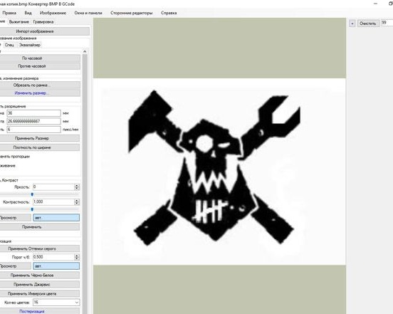
Go to the “Burn” tab. Select "ON on black." In the section "Preliminary commands" should be the following entries, without explanation in brackets:

%
G71
S255 (Laser power to maximum)
G0 F200 (Idling Speed)
G1 F100 (Burn Speed)
(F-burning speed)


You can try different burning speeds. For plastic, F100 is enough; for wood, less may be needed. Click "Save G Code" and specify the storage location. Important! Resolution should choose ".nc".

Step 8 Burning.
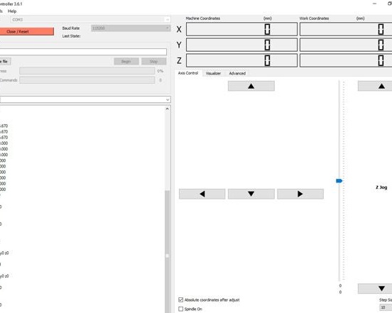
To burn and control the engraver, we will use the GrblController program:
grblcontroller361setup_1421882383496.rar [4.35 Mb] (downloads: 693)


Download and install it. Click "Open." After checking that everything works, using the arrows and the laser turn-on command, select the file you saved and send it to burn by pressing “Begin”:
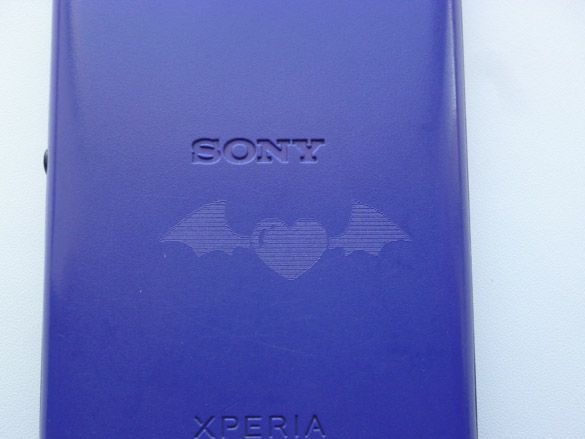


Video engraver:


9.7
9.2
9.4

Add a comment

    • smilesmilesxaxaokdontknowyahoonea
      bossscratchfoolyesyes-yesaggressivesecret
      sorrydancedance2dance3pardonhelpdrinks
      stopfriendsgoodgoodgoodwhistleswoontongue
      smokeclappingcraydeclarederisivedon-t_mentiondownload
      heatirefullaugh1mdameetingmoskingnegative
      not_ipopcornpunishreadscarescaressearch
      tauntthank_youthisto_clueumnikacuteagree
      badbeeeblack_eyeblum3blushboastboredom
      censoredpleasantrysecret2threatenvictoryyusun_bespectacled
      shokrespektlolprevedwelcomekrutoyya_za
      ya_dobryihelperne_huliganne_othodifludbanclose
61 a comment
Author
Guest Dmitry,
Try setting the idle speed with the G0 200 command.
Also try another LaserGRBL program, you can download it here https://lasergrbl.com/download/. It is simpler and more convenient.
Guest Dmitry
Thanks, the teams registered. But in the grbl controller, the motors do not respond to commands, or rather do not react at all in any way. There is food on the shield.
I would be very grateful if you leave the coordinates in order to contact you directly, homemade first, experience zero, and this Monday the preliminary diploma defense, a working machine is needed

Guest Dmitry,
Error 22 when attempting a shift.
Author
Guest Dmitry,
Good afternoon. Try entering commands one at a time. And try if there are dots, to separate the integer part of the number - put commas. And vice versa, if commas, change to dots
Guest Dmitry
Hello. Error 3 when trying to make
$100=106,67
$101=106,67
$102=106,67

$130=38.000
$131=38.000
$132=38.000

With other commands there is no error. When you try to enter your entire operating parameters entirely, error 11.

Guest Dmitry,
the laser is turned on by command.
Author
Guest Dmitry,
Good afternoon. The laser is connected through a transistor to pin Z +. You need to connect to the white pins, black all GND. Yes, all three jumpers must be installed.
Guest Dmitry
Hello, I didn’t understand how to connect the laser from the article. As I understand it, it should be soldered to one of the two Z + sheaths on the shield, but in the photo you have these legs empty.

And also to set the motor step, jumpers must be installed on all 3 pairs of contacts - Mo, M1, M2?
Author
Guest Gerasim,
https://github.com/gnea/grbl/releases
Guest Gerasim
Where is HEX? Where to get it?
I have one with a rum dvd, and the other with a rum dvd, in theory there should be bipolar ones ...
NomanGRBL only works with bipolar stepper motors, which ones do you have?
Hello, for some reason shagoviks do not work, in GRBL Contoller I set the speed so there are no erors, it shows what works. I sort of set it correctly on the pins, rang the windings and connected on the pins on the shield (tried to change places), but there was no reaction. What may be the problem, I don’t understand ...
Definitely not a DVD laser. His lot is wood and plastic, and only dark. And only engraving, not sharp.
Author
Good afternoon. I definitely can’t tell you, since I did not engrave on metal.
Guest Rinat
to burn out on a metal surface what power does a laser need?
ANDREW CHULKIN
If you use a 1W laser, then you simply do not have enough laser power to engrave halftones. On the forums they write that for a halftone you need at least 2 watts of laser. I also do not engrave a half-tone with a 1W laser, I ordered 5.5W, and we'll see.
vitarezoff
with this PWM laser connection scheme, laser power adjustment is present. I understand correctly? The m3 s10 team turns on the laser dimly, the m3 s100 is brighter, and the s255 is at full power. in my case, anyway. why then does the laser not produce a halftone on the burned picture? the control program gives different values ​​of the power S in gcode when passing through the shades, and it is visually visible that the laser goes out and becomes brighter, but the picture still only black and white ...
Author
It’s clear, apparently your steps are not standard.
Or maybe the motor drivers are configured to limit current at 12 volts, then when you connect 5 volts, the current strength will be too low for them to work.
Simply, according to the datasheet for these engines, they work from 5 volts, I don’t know how they will behave at 12. But if it works and does not cause problems, then 12 volts is normal.
vitarezoff
I connected the shield from the 5V PSU. Stepper wheel drives stopped working. Switched back to 12V and everything spins.
Author
Yes, such a voltage range is written on the shield. But the voltage must be selected for the stepper motors that you use. If these are DVD \ CD engines, then they are rated at 5 volts.
Author
Happy to help
vitarezoff
I replaced the transistor with TIP 122 and it worked. Thanks for the tips.
vitarezoff
It turns out that both CNC Shield and laser can be powered from a single 5V unit?
After all, 12-36V is painted on the shield board. I fed the 12V shield and the stencil did an excellent job with pen drawing.
Author
Replace the transistor.
Perhaps there is not enough voltage to close the transistor, the resistor, in front of the base of the transistor, is designed for TIP120.
For your transistor, you may need a smaller resistor, but this is an assumption.
Author
Minus should be taken with GND. You can’t take Z-pin. This is the pin of the Z-axis trailer.
The easiest way is to fasten the shield to the power label of the shield in the negative wire, or use the GND shield.
If you use stepper motors from DVD \ CD, then you need to power them from 5 volts, respectively, and the shield too.
vitarezoff
Combined minus BP laser with minus shield. When the command M3 S255 appears power 5.07V based on the transistor. Between the plus of the laser and the minus of the shield, there is also 5V. It looks like the problem is in the transistor. Further its minus does not pass. I cross the legs of the emitter and the collector on the transistor and the laser is cut.
vitarezoff
Thanks. My minus PSU is not connected to the minus shield. Most likely the problem is this. In the evening I will check.
And yet my shield is powered by a 12 Volt power supply, and the laser from a laboratory technician is 5V.
Is it possible to take the minus from any pin of the shield to connect with the minus of the power supply? Or just from the pin next to Z +?
Author
Good afternoon. If a signal appears on Z + it means everything except connecting the laser is done correctly. Plus, the power supply must be directly connected to the laser. Minus through the transistor. The minus of the laser power supply and minus the arduino should be connected to the transistor. You need to consistently check the entire wiring diagram:
Turn off the laser, turn on the engraver
Check the voltage between the plus of the laser (the wire that should be connected to the laser) and the minus of the power supply, if there are 5 volts, go ahead, if not, look for a problem with the power supply or wires
Check the voltage between the plus of the laser and the minus of the shield (or arudino), if there are 5 volts, go ahead, if not, connect the minus of the shield (arduino) and the power supply to the supply laser.
Turn on the laser through the program (command m3 s225), check the voltage at the laser contacts, if there is 5 volts, the laser is faulty, if there is no voltage there is a problem in the transistor. Perhaps it does not fit or burned out.
vitarezoff
5V power on z + appears when I send the m3 s255 command to grbl, and when I send m5 it disappears. but the laser does not light up. at z + cnc shield we take only one plus to the base through the resistor? minus leads the transistor as I understand it. It would be nice to draw a diagram.
the transistor took an analog 7rf7 (kt817g it is)
what do you advise?
.
Author
Good afternoon. It’s better not to do this, since the 5 volt on the CNC shield comes from the 5V pin Arduino. And the Arduino is powered by a USB port, where the current strength (when using UBS 2.0) is a maximum of 500 mA. The laser needs an external power source. If you use a laser from a DVD drive, the current can reach 800 mA. And this is the smallest possible laser. A laser with a higher current strength will burn well.
vitarezoff
Is it possible with such a circuit to take 5V from the CNC Shield board as a laser power supply. I now have a servo so connected instead of the Z axis.
ganzubas
Quote: Lefty
So connect through the transistor according to the scheme given by the author and you will be PWM.

Yes indeed, it worked! I would also like to make an audio signal at the end of the process of burning (cutting). Who knows how this can be done?
Author
I think this is a hardware problem. One of the drivers may be faulty. Or a connection problem, check the quality of the contacts.
Thanks for the clarification, another such question. I have such a problem, when 2 A4988 drivers are connected, one of them starts to slow down (one axis) or does not respond at all, but if one driver works, this problem disappears. There is definitely enough current, the power supply is powerful.
Before scrapping "here" in a previous comment link
So connect through the transistor according to the scheme given by the author and you will be PWM.
After these commands everything worked, but could you give me a link to this information (what kind of teams)
The laser started working after these commands. And where can you find out more about these, you do not have a link?
ganzubas
I collected and connected everything in accordance with the article. Everything works except the laser. More precisely, it also works (glows), but no more. Laser without PWM 1500 mW 5 volts. If I connect it to the contacts Z + and GND, I get just a blue "flashlight". And if you directly apply 5 volts to it, bypassing the CNC nameplate, then the laser starts to cut normally. What could be the problem?
It is necessary to set the feed rate: F500
Try the commands:
M3 S255
F500
G1x1
Author
Good afternoon, you can read the error description: https://github.com/gnea/grbl/wiki/Grbl-v1.1-Interface
There in English, but with the help of a translator you can figure it out.
Most likely, the controller swears at the lack of setting the speed.
The first lines when burning or starting work should be:
G71 - activates the operation mode with metric data.
S255 - laser power
G0 F200 - idle speed
G1 F100 - Burn Speed
Try entering these commands first (without explanation).
grblcontroller361 throws error Erorr22. What is this mistake?
I have the same problem, when I turn on the laser (M3 S255) I measure the voltage on the Z + connector, but it is not there. Firmware GRBL 1.1f.
Author
Good afternoon. The connection photo is in the article above. But there is nothing special there. The CNC shield is placed directly on the arduino, and stepper motors, a laser and power are already connected to the shield, to specially output and signed contacts. If you have questions - ask, I will try to help.
I will try to do it. What kind of wires do you have difficulties with? Do you use a shield?
Guest Andrey
If not difficult, you can photograph the connection of wires to the arduinka ... I will be very grateful
my laser starts only after the commands:
M3 S255
F500 (Travel Speed)
G1X1 (X-axis movement)

In any case, everything works. Thank you for the article!!!
Author
Good afternoon. When I issue the M3 S255 command, my laser turns on. Carriage movement is optional. Try checking out the GRBL version. Depending on the version, the output to which the laser is connected is different.
Same problem as Andrei Chulkina
On the leg (D 11) Z + minus, does not respond to commands “M”.
On 3dtodey they write that the laser will not turn on until the steps have started to move, but my G code is created without the laser start command.

We advise you to read:

Hand it for the smartphone ...