

Have a nice time, friends! In this article I will tell you and show you the current model a cyber robot that can not only speak in the voice of the operator repeating his words, but also go around obstacles in its path!
Materials and tools:
- crawler platform -2pcs. (Taken from the Broken Tank Battle game set)
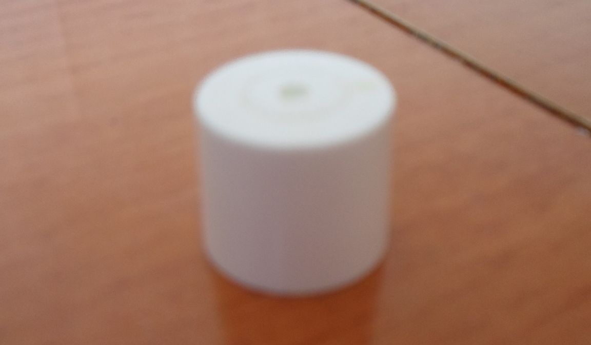
- plastic caps from toothpaste -2pcs.
- Super glue
- aluminum billets
-finished electronic modules + their operating time
- drill
- files
And so we proceed:
Part 1. "Mechanics"
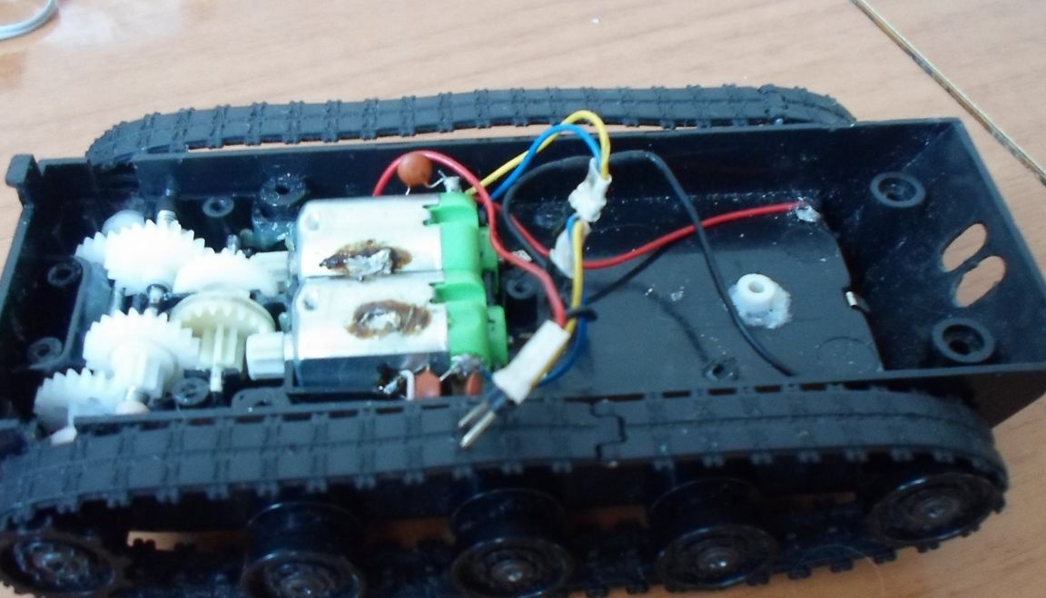
The caterpillar platform from toy r / y tanks was taken as the basis for the design of the cyber robot (“tank battle” consisting of a set of two tanks, see Photo 1.)

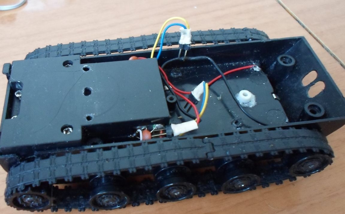
Then, after some alterations of these tanks, two main parts appeared for the construction of a cyber robot. The first spare part is used to move the cyber robot - this is the caterpillar platform itself, see Photo 2. Photo 2.1
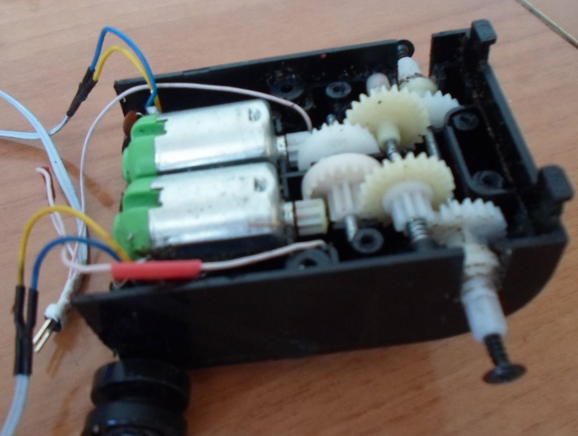
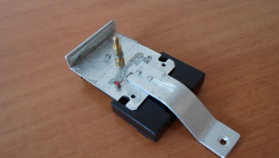
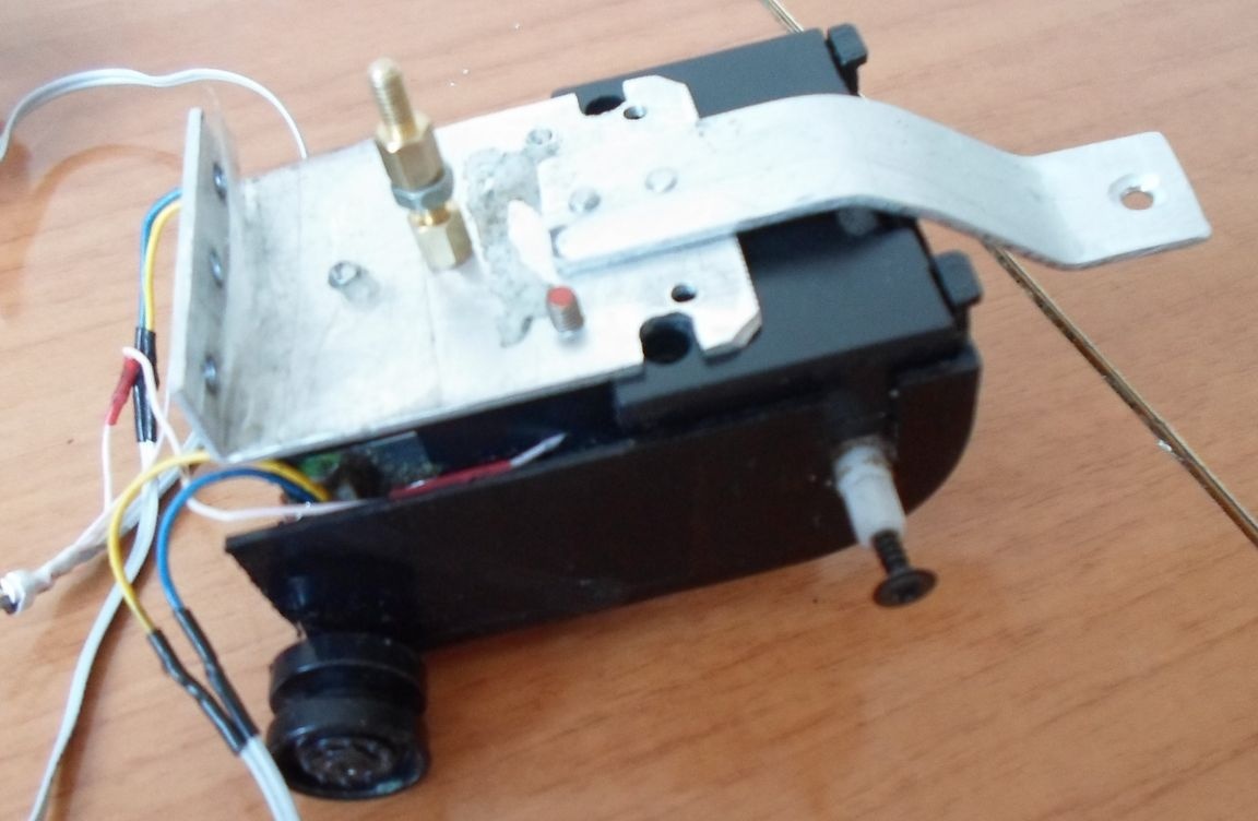
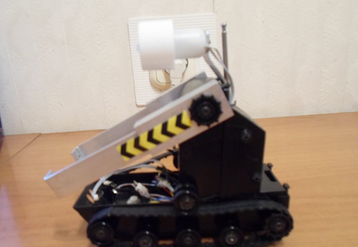
The second spare part is used to raise and lower the manipulators (“arms” of the cyber robot) see Photo 3. Photo 3.1
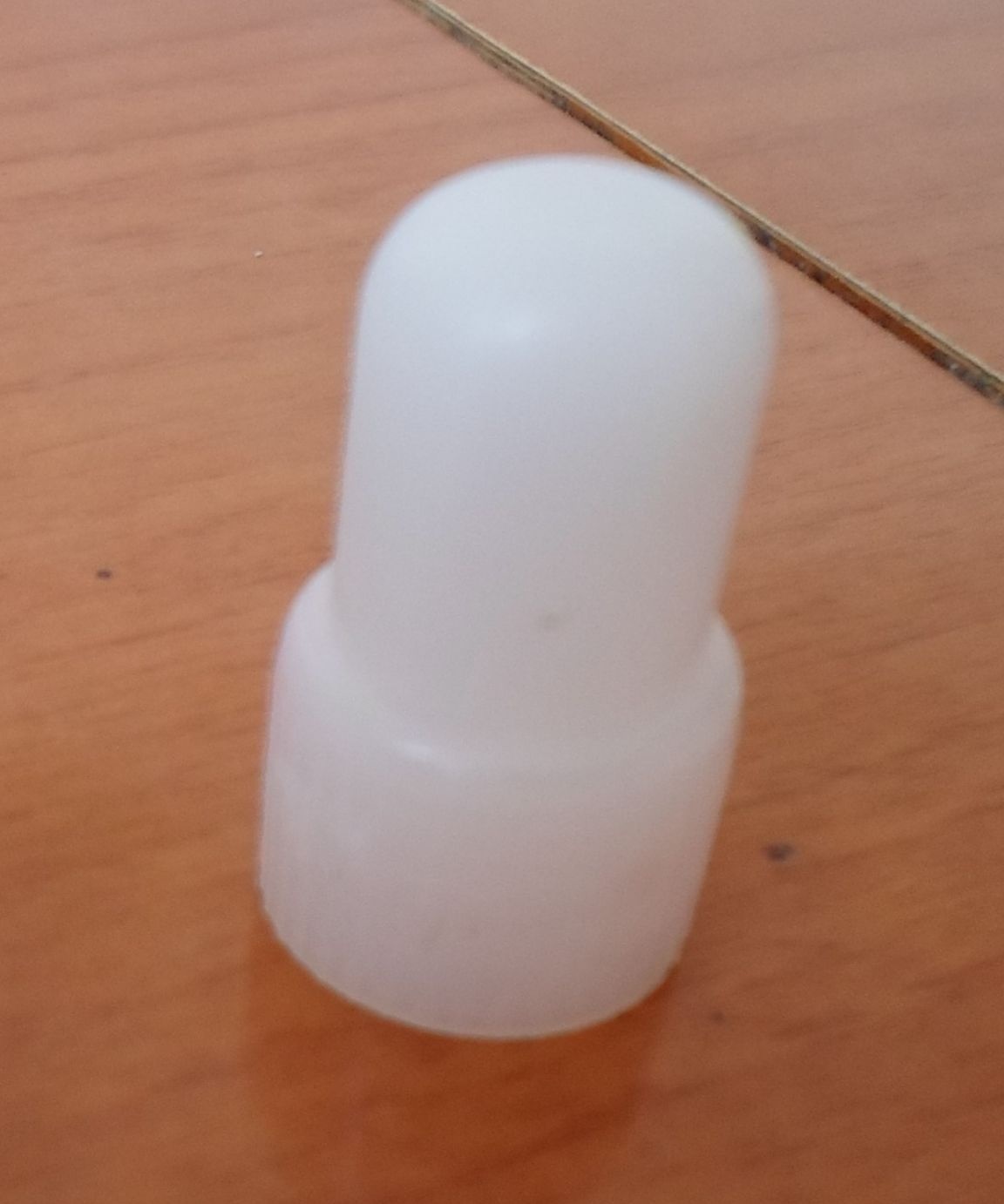
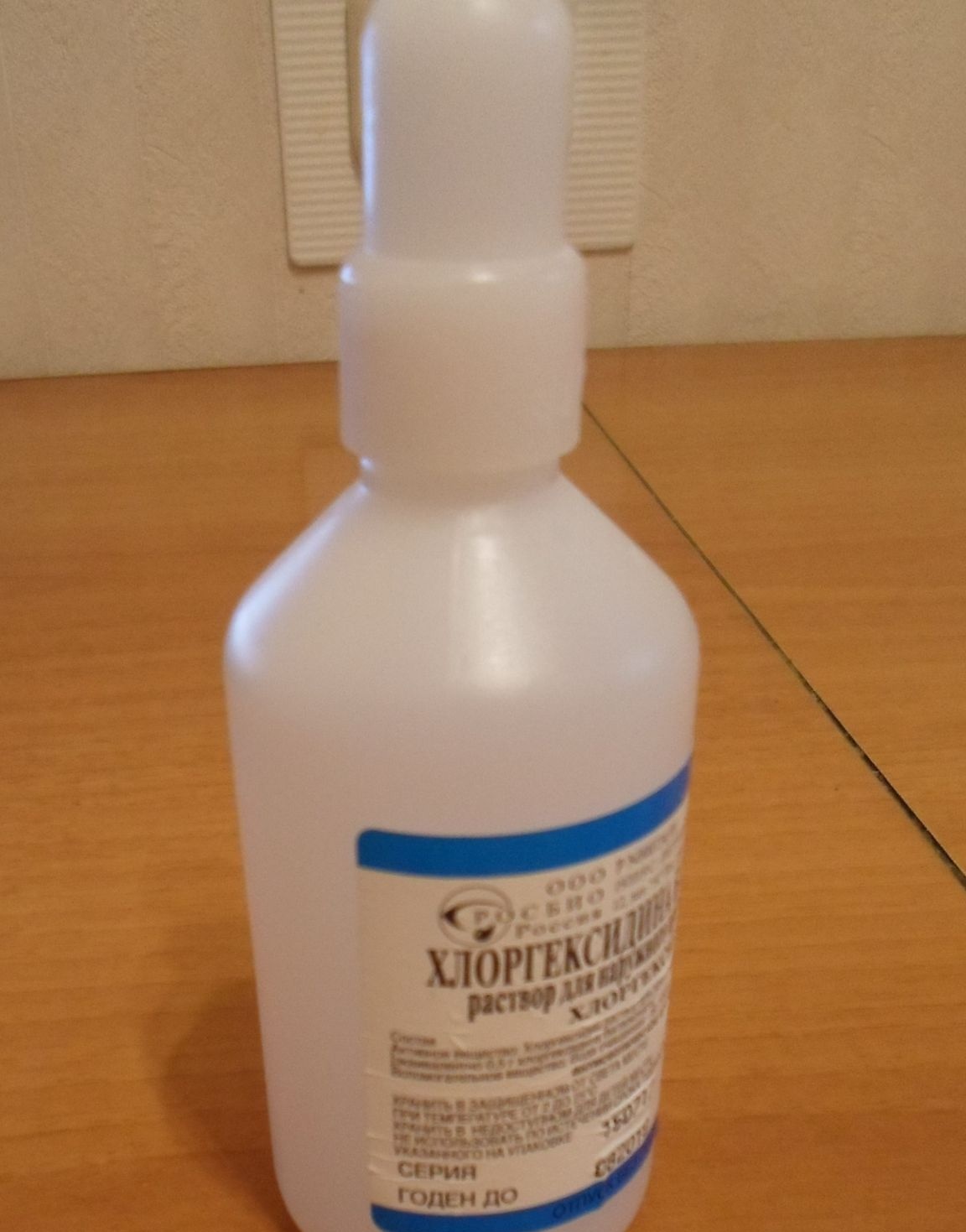
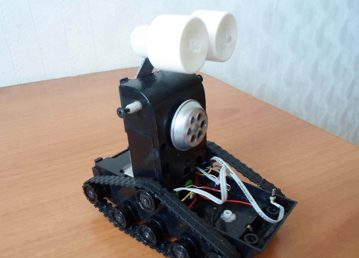
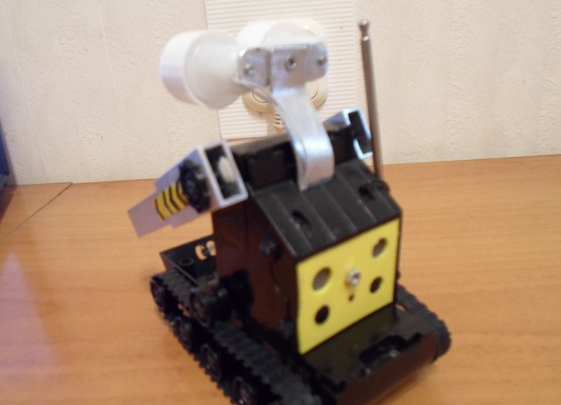
As the head of a cyber robot (see Photo 4.), I used caps from plastic bottles, see Photo 4.1 (a bottle from a medical preparation, hydrogen peroxide, see Photo 4.2)
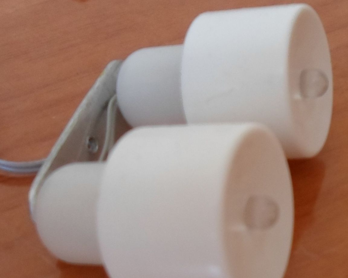
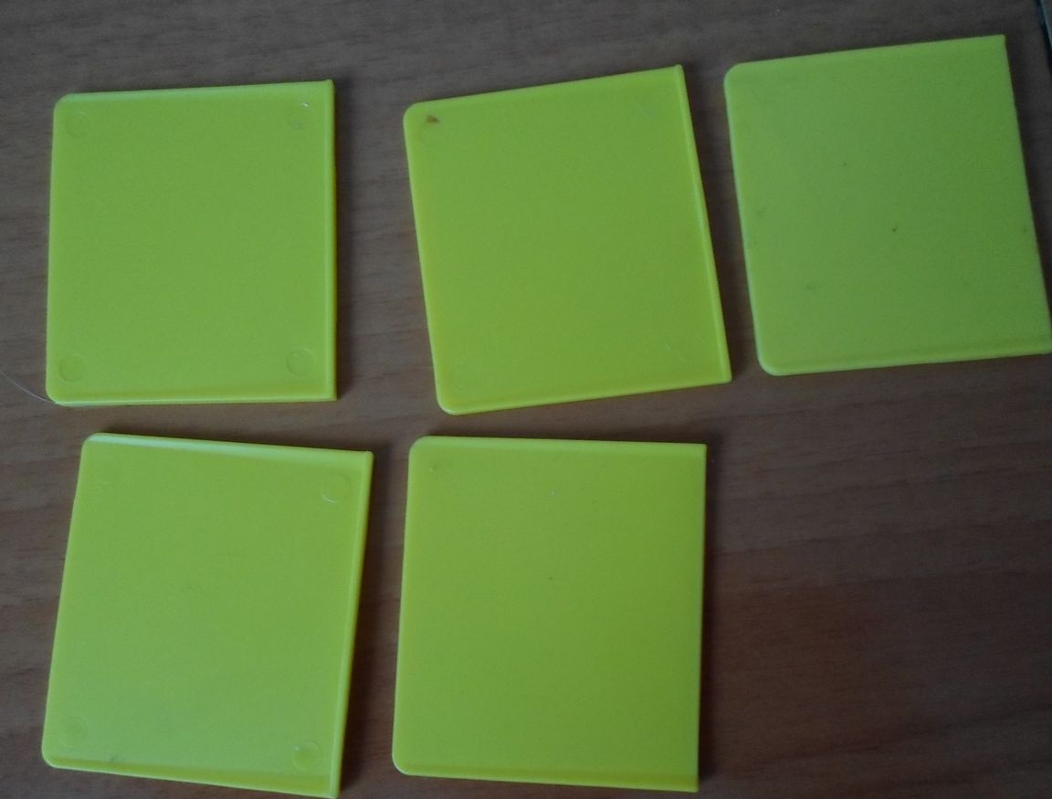
As eyepieces of a cyber robot, I took caps from toothpaste, see Photo 4.3
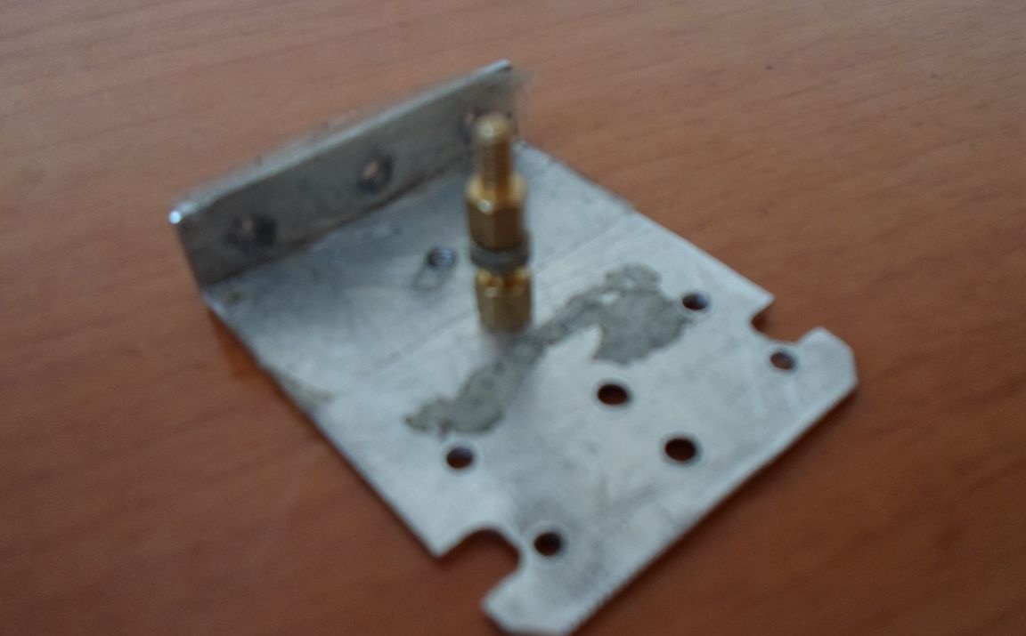
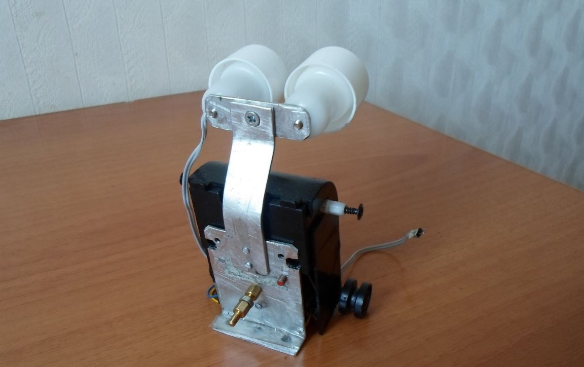
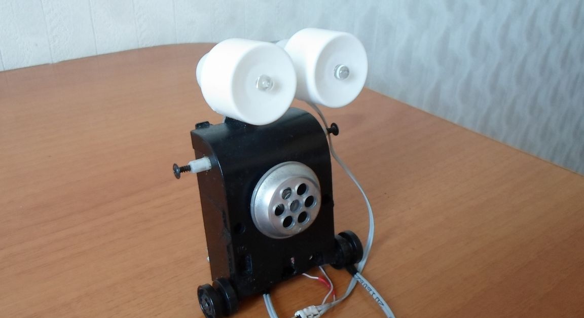
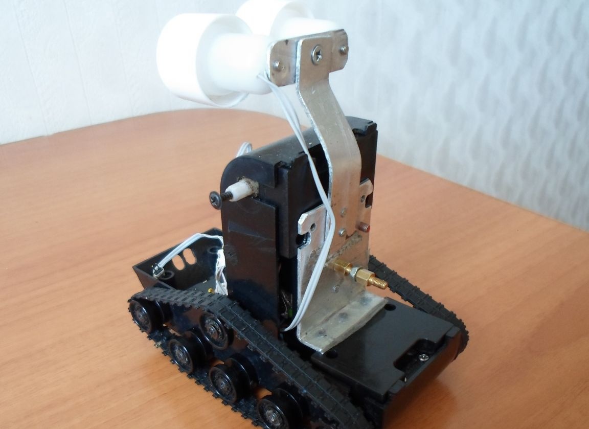
To fix all the components of the cyber robot, I used an aluminum strip of the appropriate size (see Photo 5.) and then after locksmithing (see Photo 5.1 Photo 5.2 Photo 5.3 Photo 5.4), an already visible outline of the future cyber robot was obtained, although without "Hands" of manipulators. See Photo 6. Photo 6.1 Photo 6.2 Photo 6.3
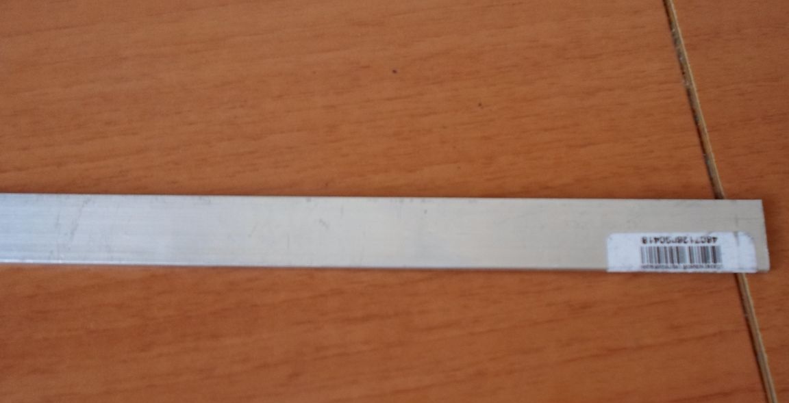
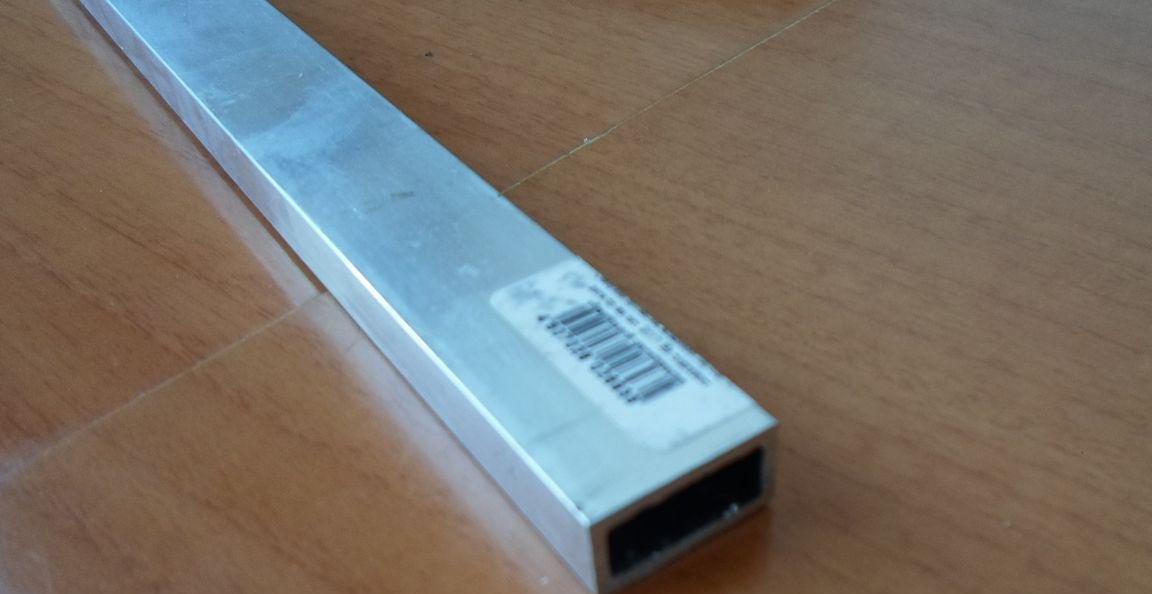
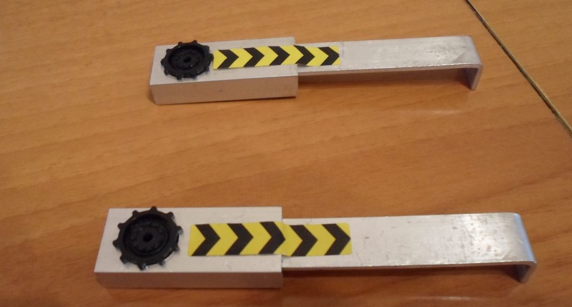
Now I will tell you how to make manipulator arms. To do this, we need an aluminum strip of the appropriate size (see Photo 7) and a rectangular tube (see Photo 8)

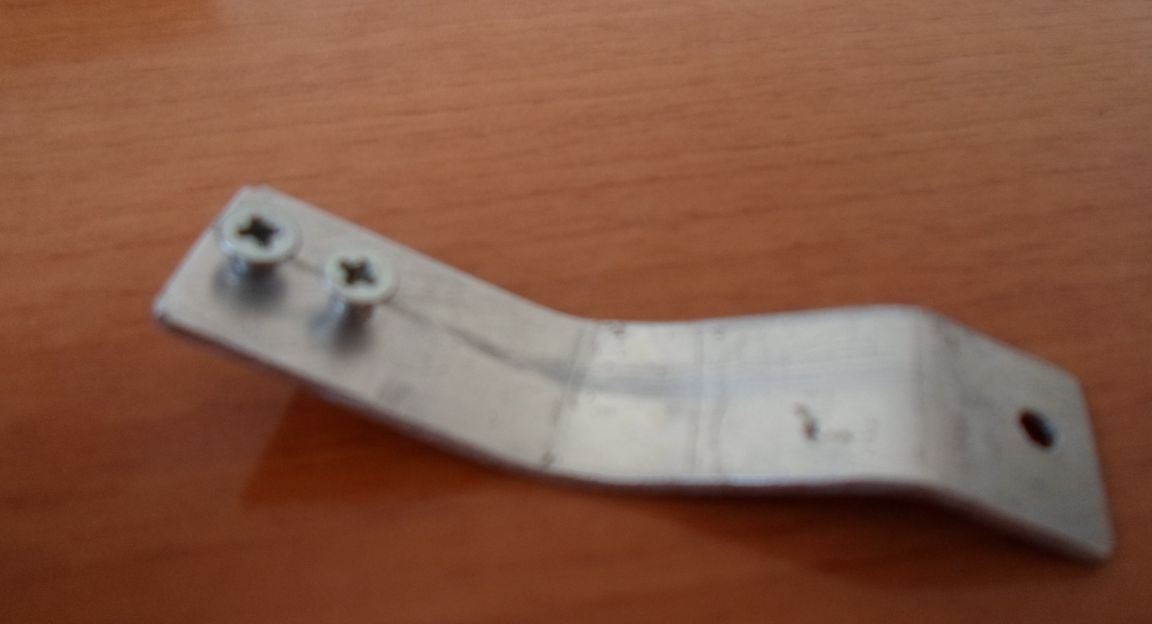
Then, after carrying out locksmithing, we get the same manipulator hands (see Photo 9.)
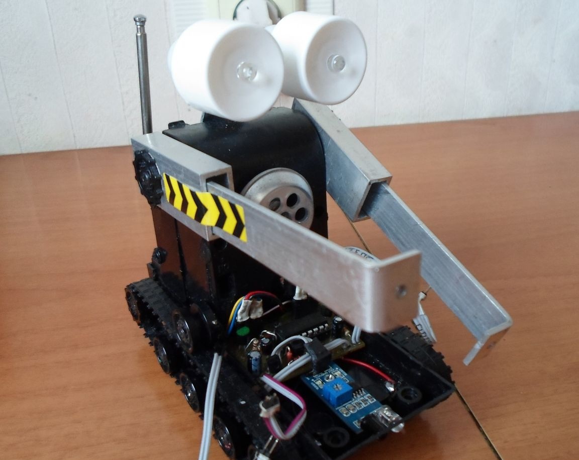
Next, we install the manipulator hands in their places and fix them with screws (see Photo 10.)
Now finally cyber robot almost assembled. But this is not all, because it still needs to be revived and taught to speak, as well as think! So now we proceed to the most important issue in this project - how to make our cyber robot move, while avoiding obstacles in its path and talking, repeating the voice of its creator!
Part 2. "Brains of a cyber robot"
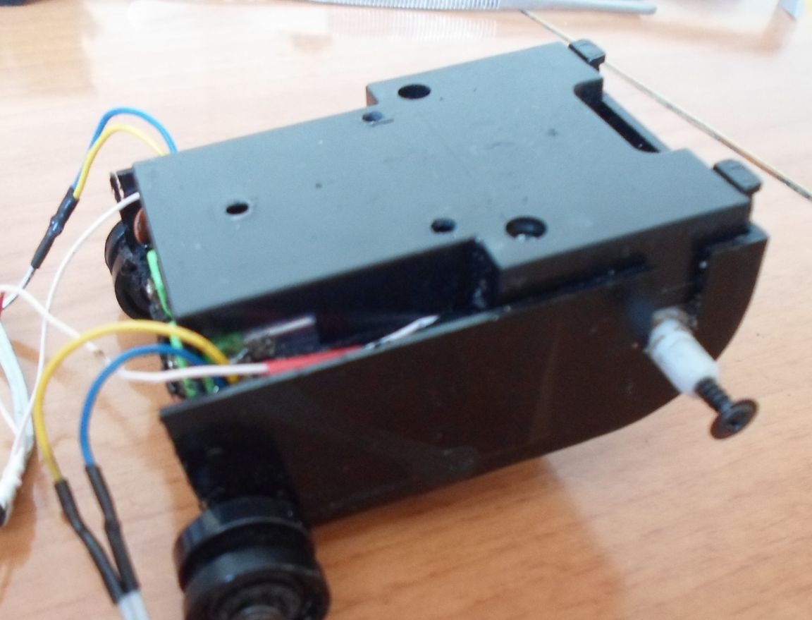
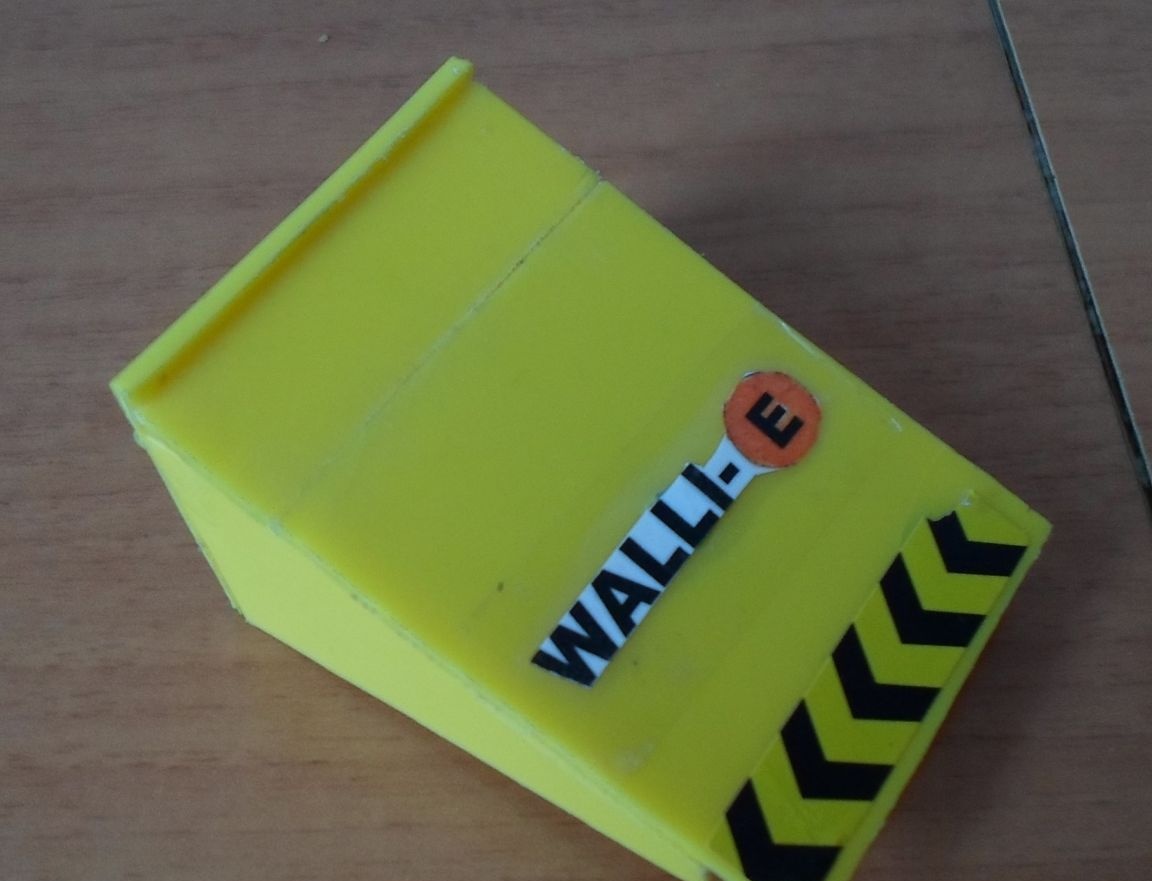
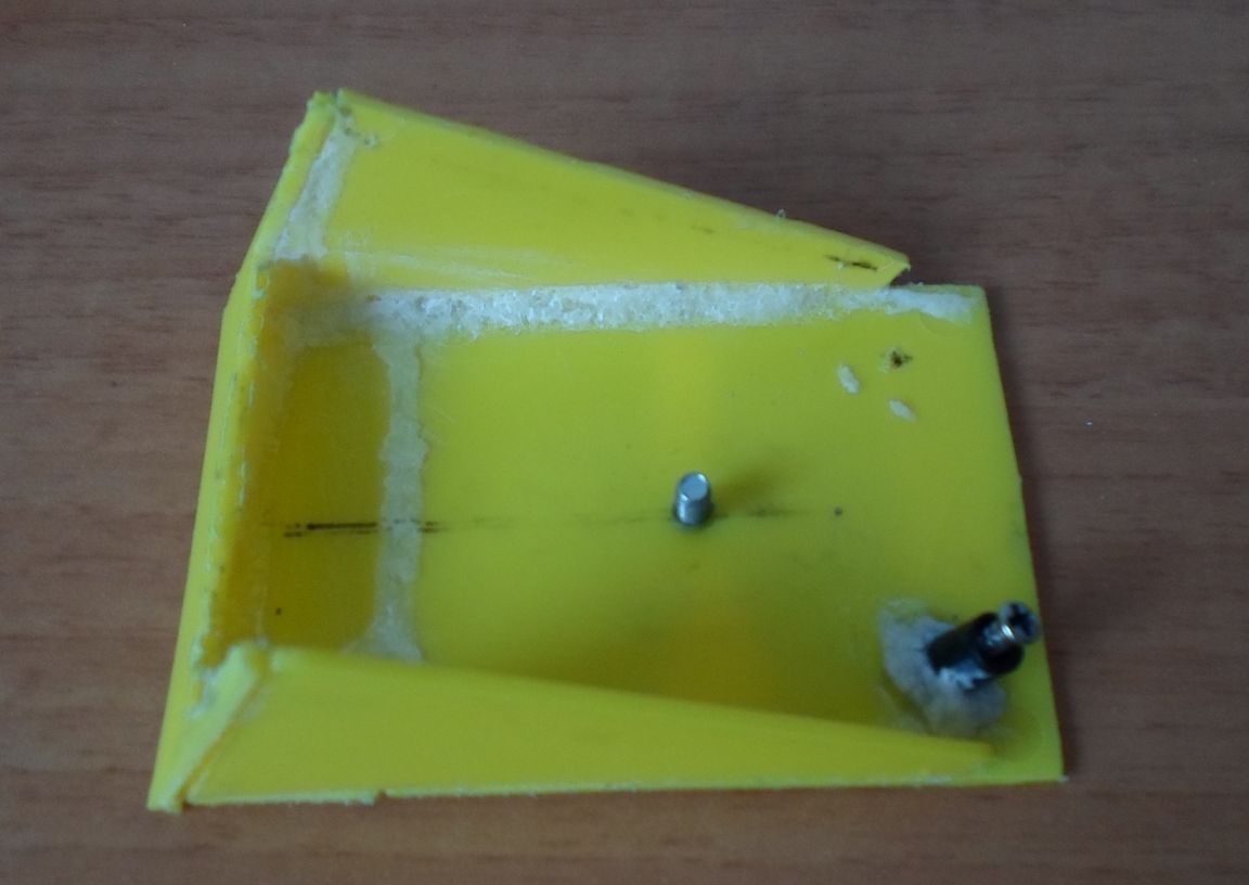
As you remember in Part 1 of the “Mechanics”, we made two main parts for the cyber robot from the spirit of toys — a caterpillar platform and a body for the “arms” of manipulators. From the second toy, we still have an unused spare part - which we can use as a housing where the electronic circuit of the voice unit can fit, after some alteration. (see photo 11.)
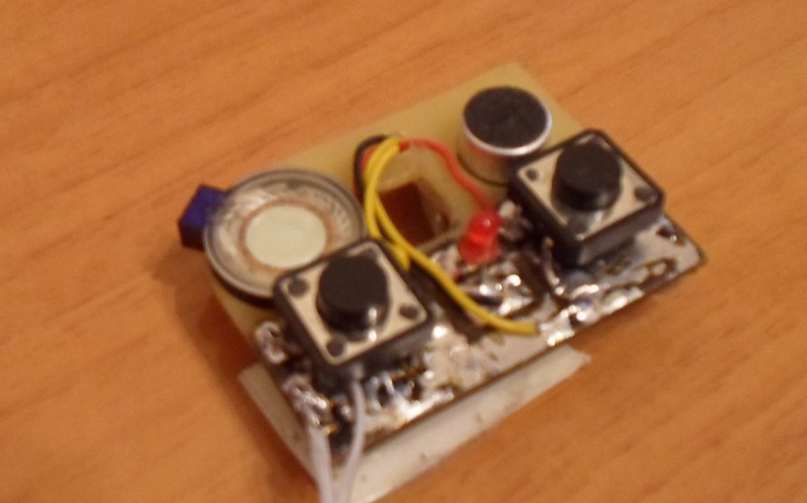
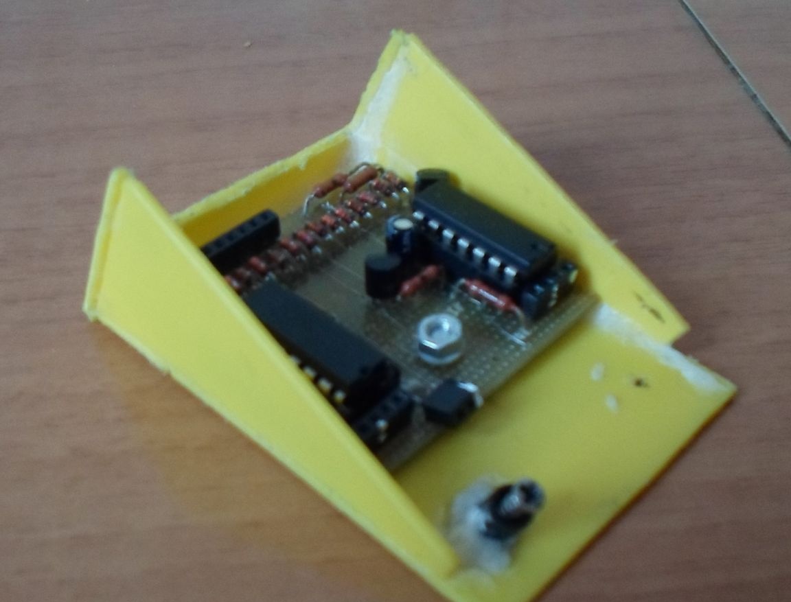
The electronic filling of the voice block is shown in Photo 12. Photo 12.1 This module was made on the basis of a ready-made circuit, which was purchased at the radio store. A general view of the cyber robot with the installation of a voice unit is presented in Photo 13. Photo 13.1
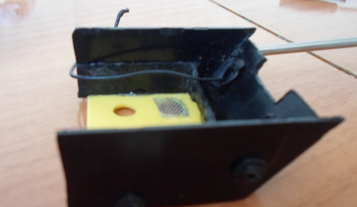
Now let's talk how to teach our cyber robot to move, while avoiding obstacles. To do this, we will need “special eyes” and a special microcircuit to control the movement motors of the cyber robot tracks. As a “special eye”, I purchased an optoelectronic proximity sensor in the radio store (see Photo 14)
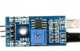
This sensor operates on the reflection of an infrared ray, invisible to the human eye, which it transmits and receives. Further, the signal from this sensor will go to our electronic motor control unit. (see Photo 15.)
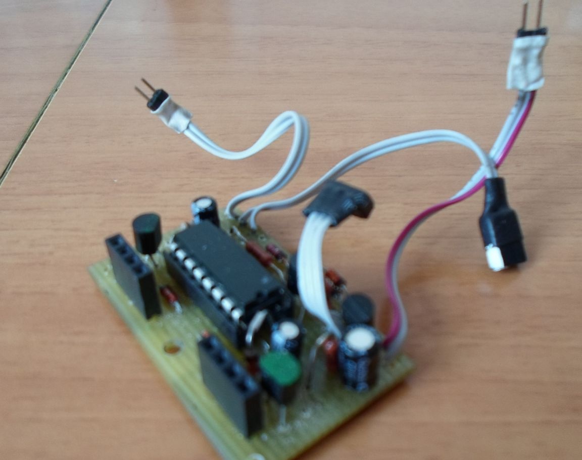
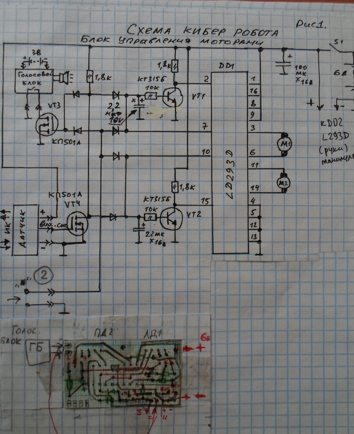
The motor control unit recognizes the signals from the sensor and gives the appropriate commands to the motors. Thus, when a cyber robot pulls a certain distance to an obstacle, it moves back from it and makes a slight turn to the side, then it follows forward. Here is such a small algorithm for the operation of the electronic motor control unit. Based on this algorithm, I developed a circuit diagram Fig. 1 General view of the location of the proximity sensor and the electronic control unit of the cyber robot motors is shown in Photo 16. Photo 16.1
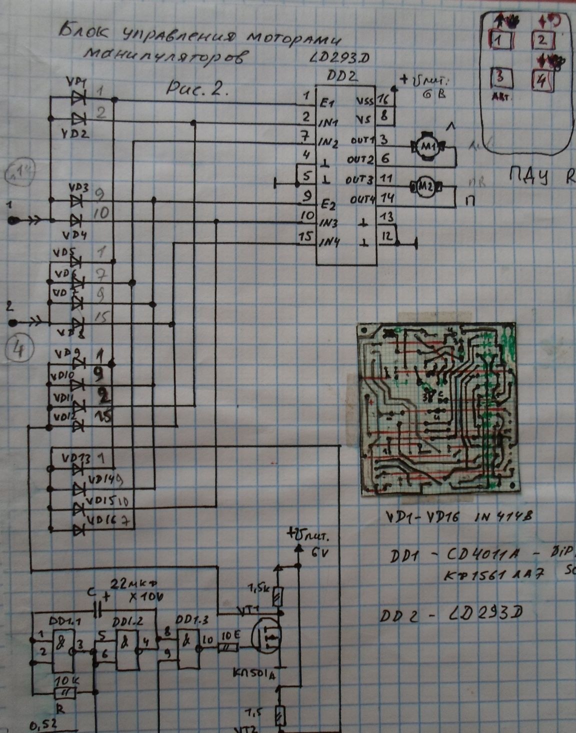
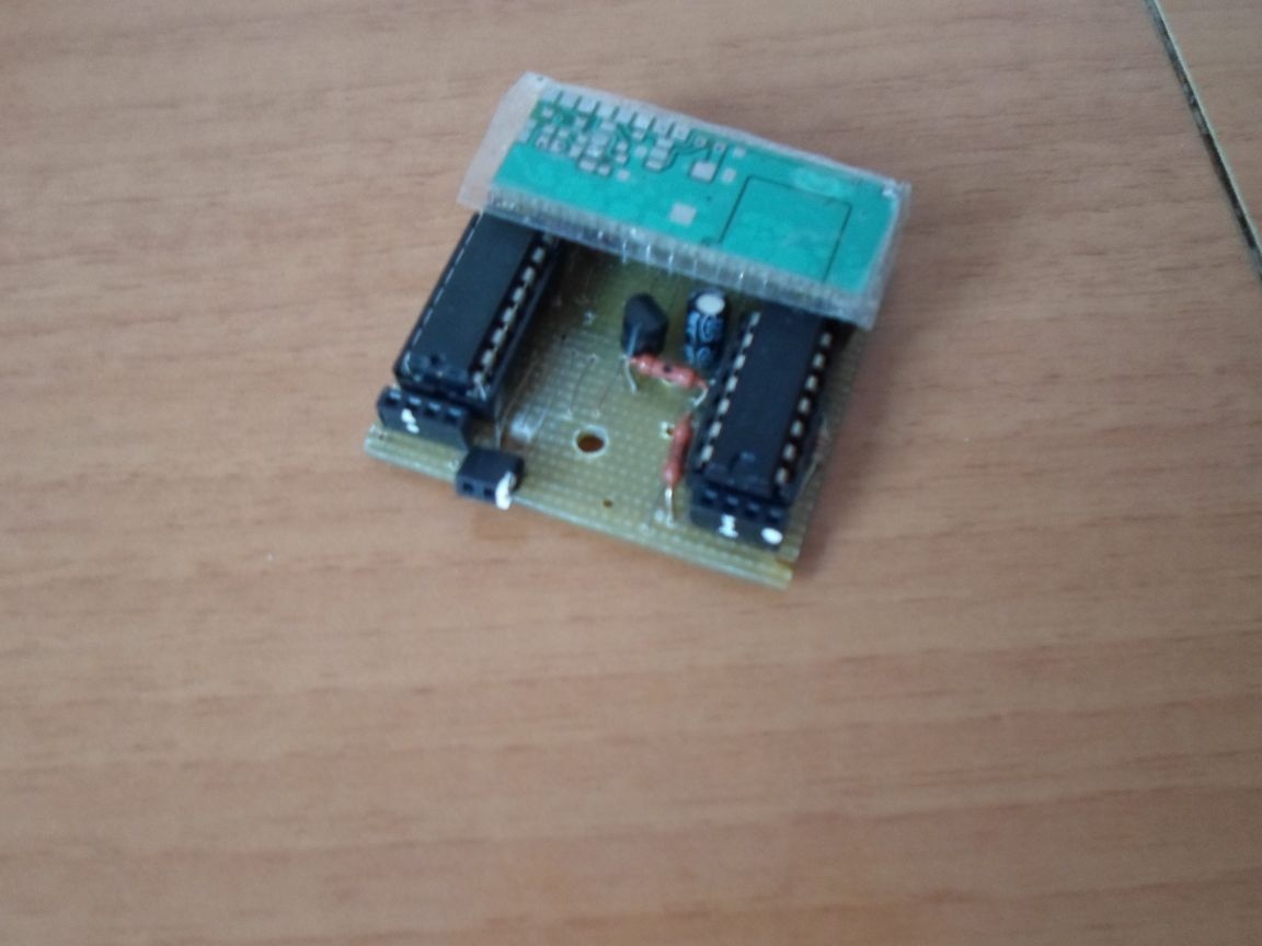
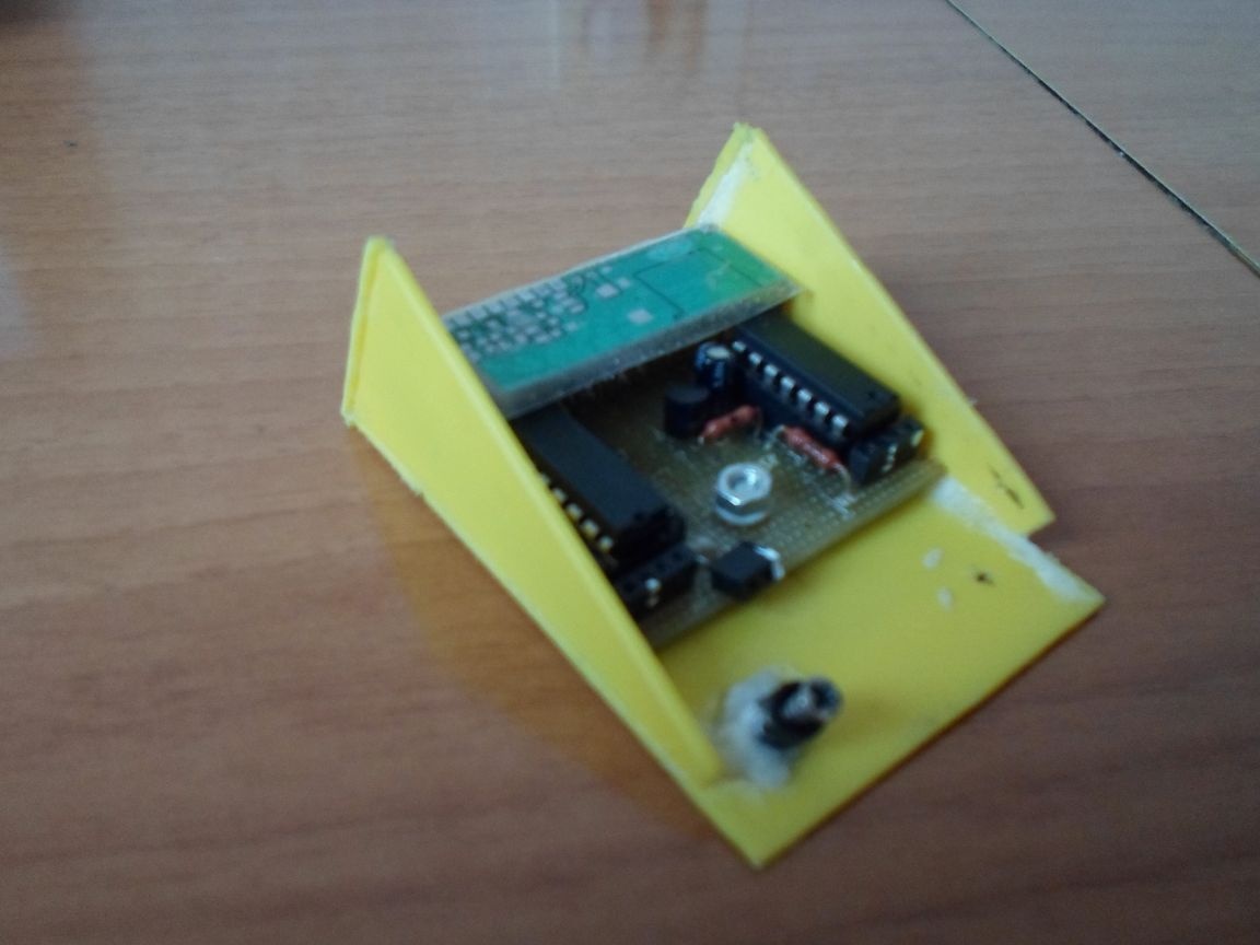
Next, I will tell you how to control the "arms" of the manipulators of a cyber robot. For this, I developed an electronic circuit for controlling the motors for lifting and lowering the “arms” of manipulators, see Fig. 2 The electronic unit itself is shown in Photo 17.
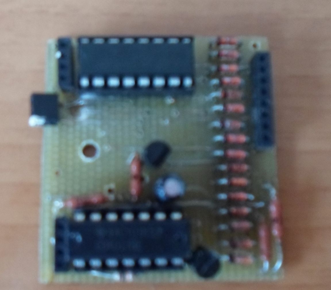
Which is located in front of the removable housing Photo 18. Photo 18.1, Photo 18.2
The removable housing is designed and made by me from improvised materials. As a material, I used plastic partitions from the box for small parts (see Photo 19 Photo 19.1)
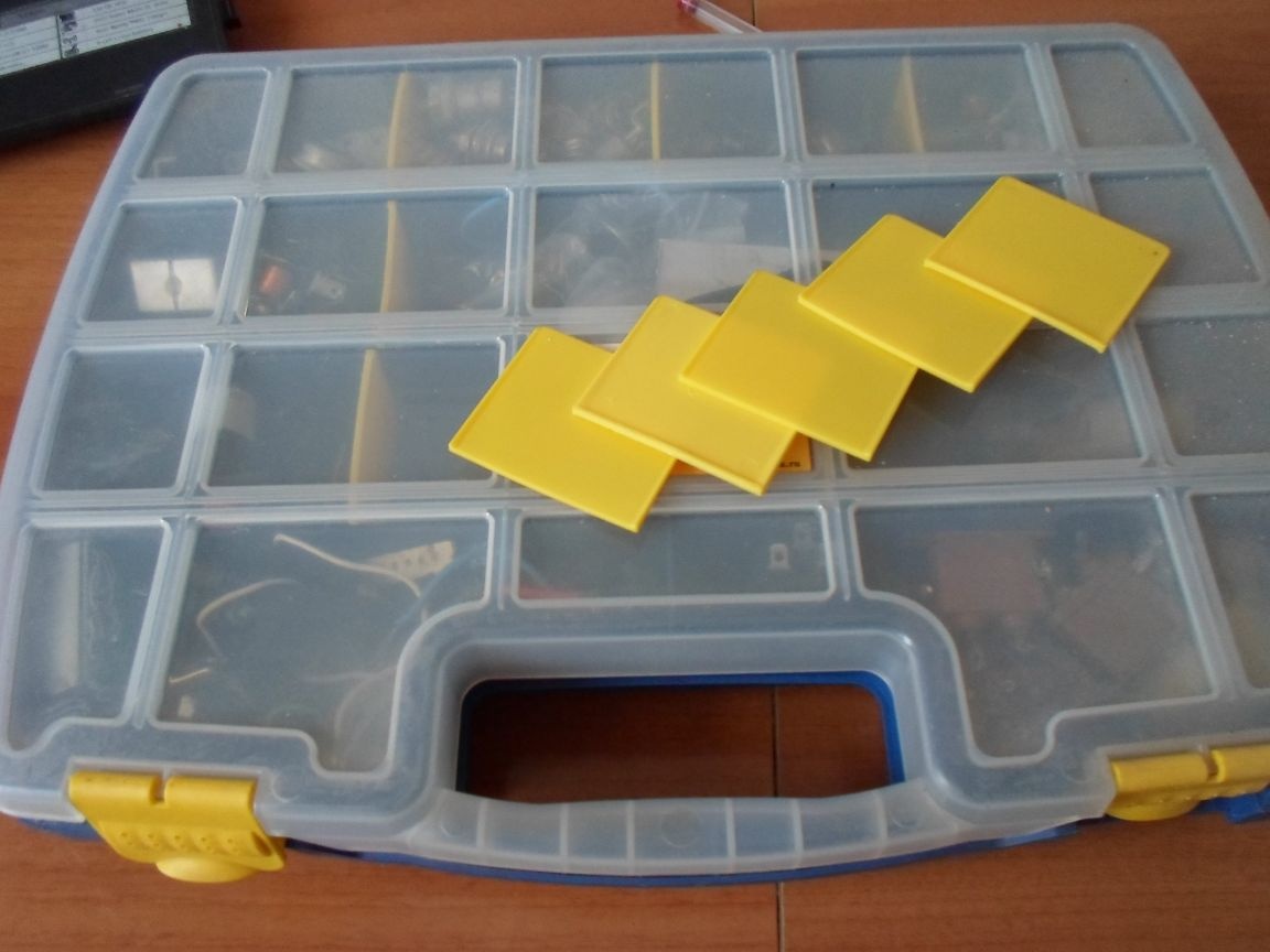
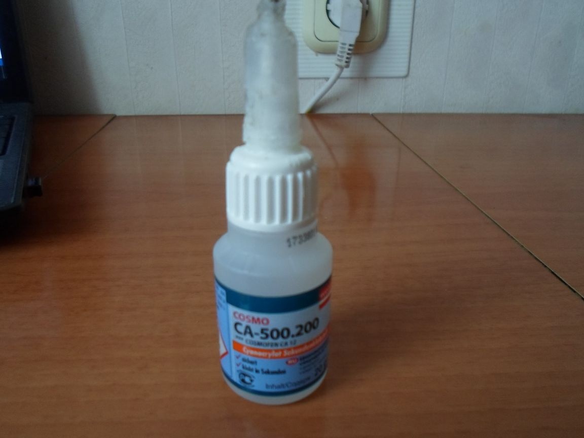
Pre-prepared blanks of the future removable housing were glued with special glue for plastic (see Photo 20)
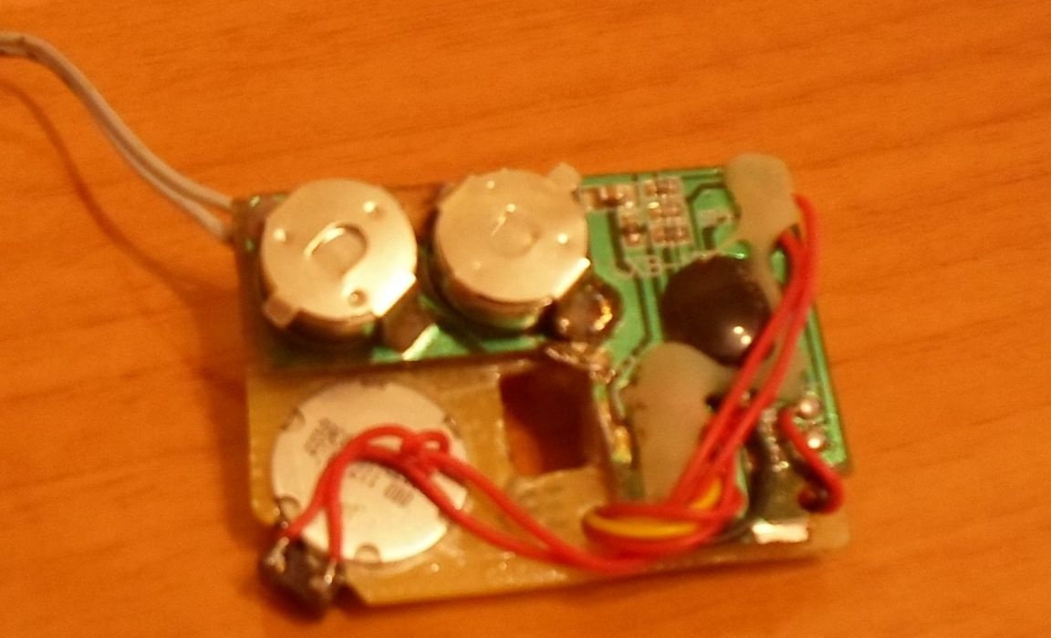
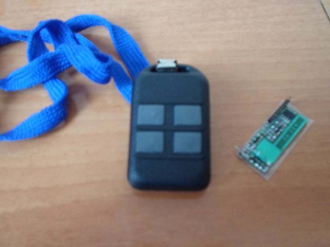
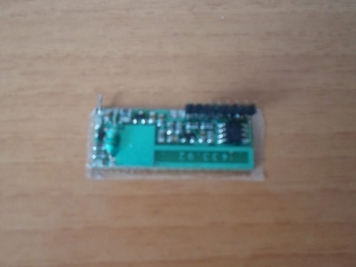
For remote control of a cyber robot, I used a ready-made electronic kit consisting of a remote control and a radio signal reception board (see Photo 21). I placed this radio receiver board along with the manipulator motor control board of the manipulators in a removable cyber robot body (see Photo 22 Photo 22.1 Photo 22.2)
A receiving antenna for controlling a cyber robot is located on the body of the voice unit (see Photo 23).
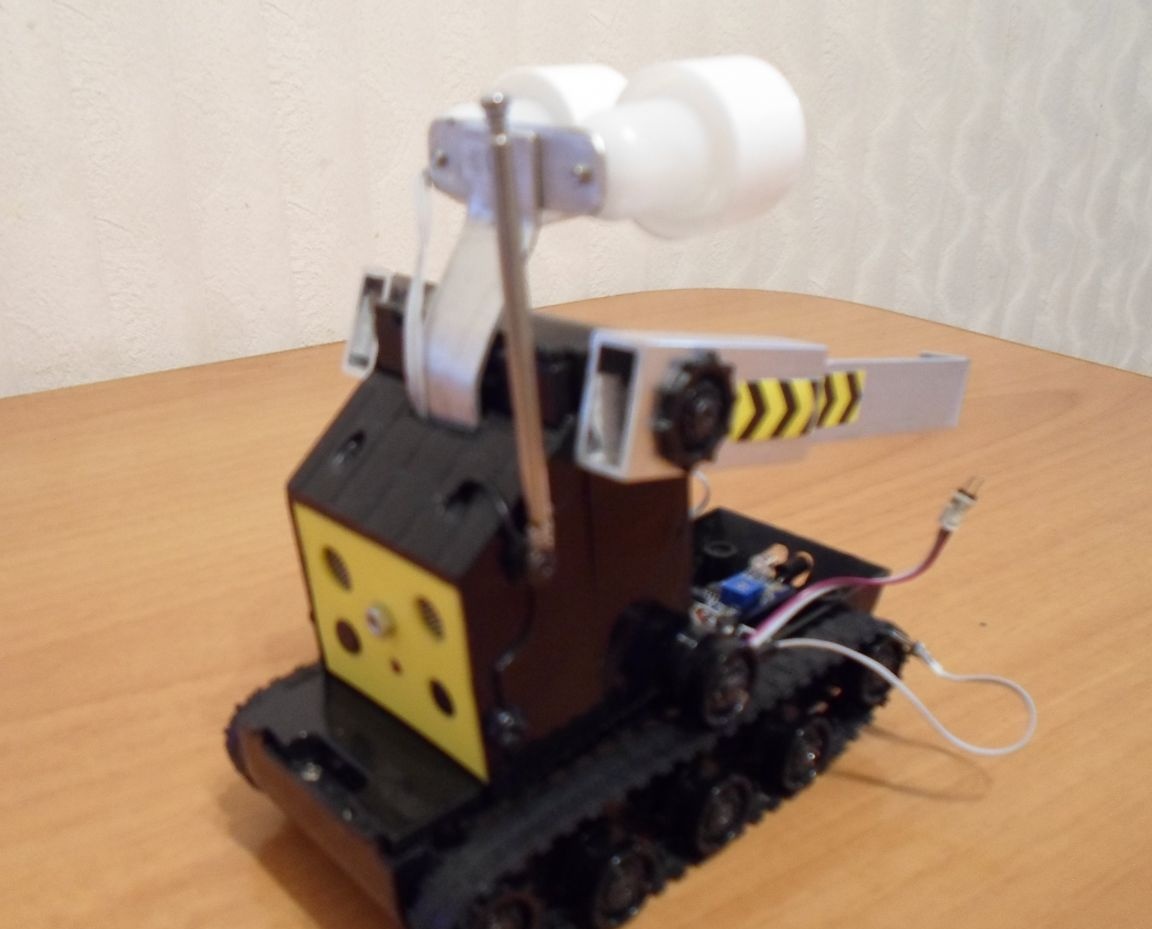
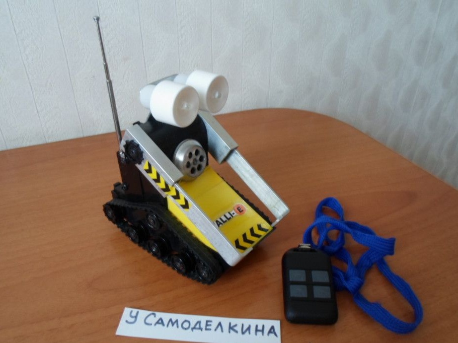
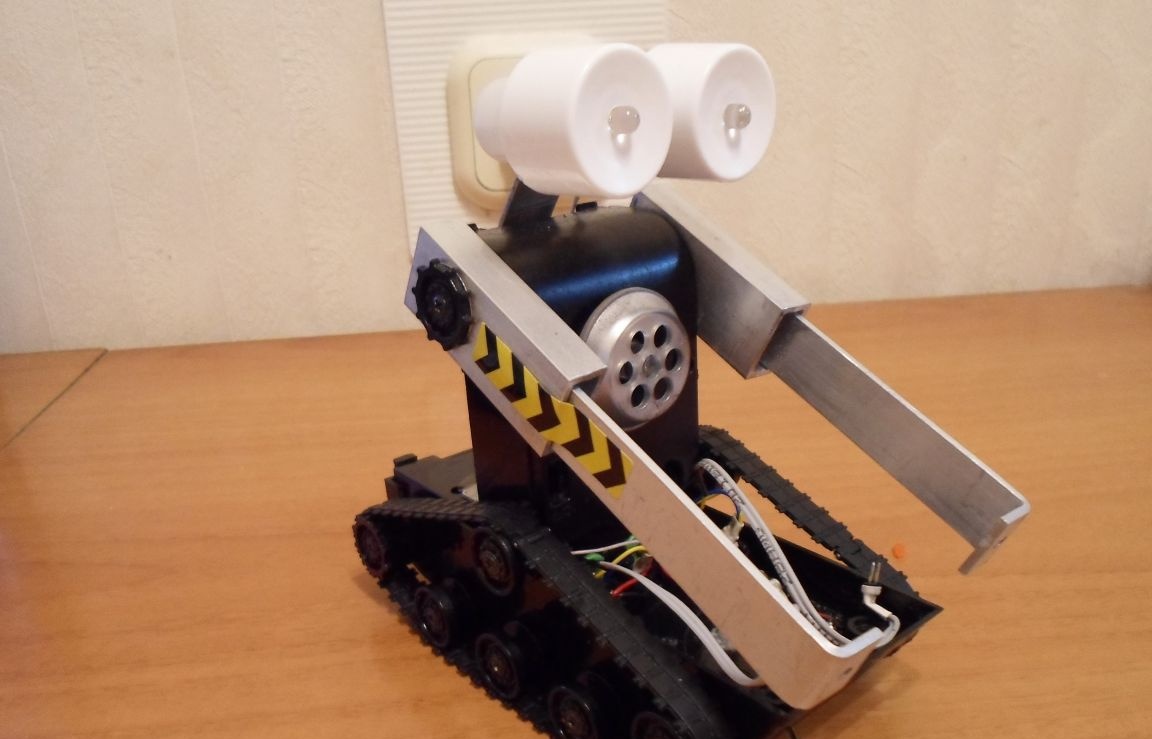
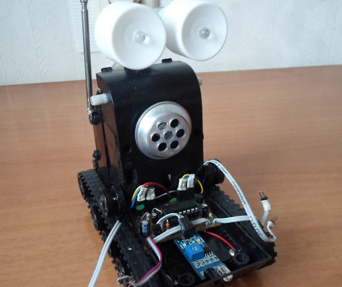
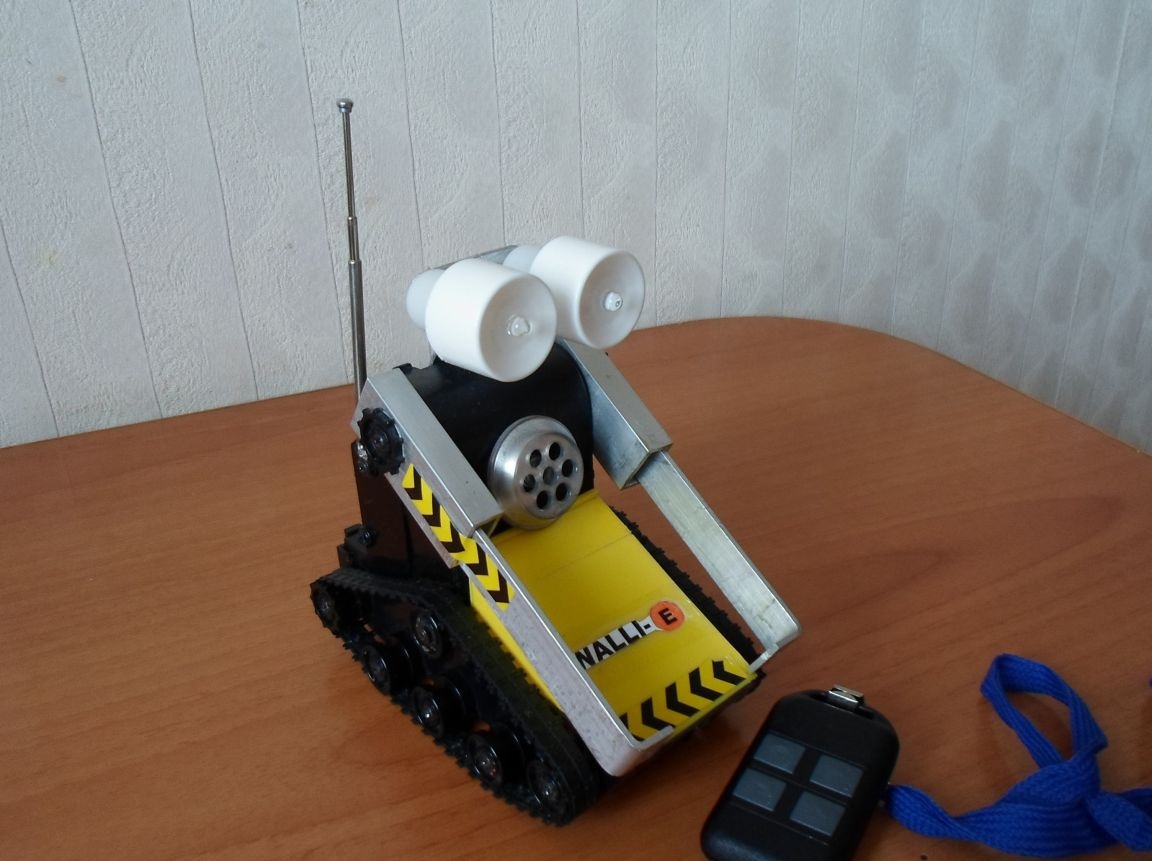
For a more expressive and attractive look, I installed multi-colored flashing LEDs in the eyepieces and on the chest of the cyber robot. Now it remains to assemble all the nodes of the cyber robot into a single whole. Well, meet the cyber robot WALLI-E !!! Photo 24.
Part 3. “On-board power supply”
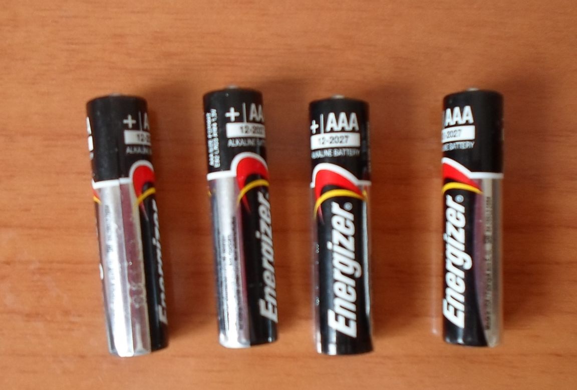
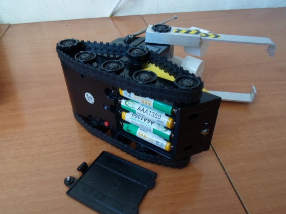
In the process of operating a cyber robot, much attention has to be paid to batteries. Initially, I conceived the power of a cyber robot from ordinary AAA 1.5V 4pcs finger batteries. (see Photo 25.)
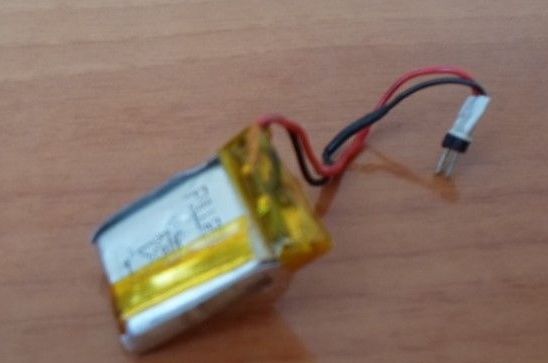
The radio module is powered by a separate 3.7V 150mA / h Li-On battery, see Photo 26.
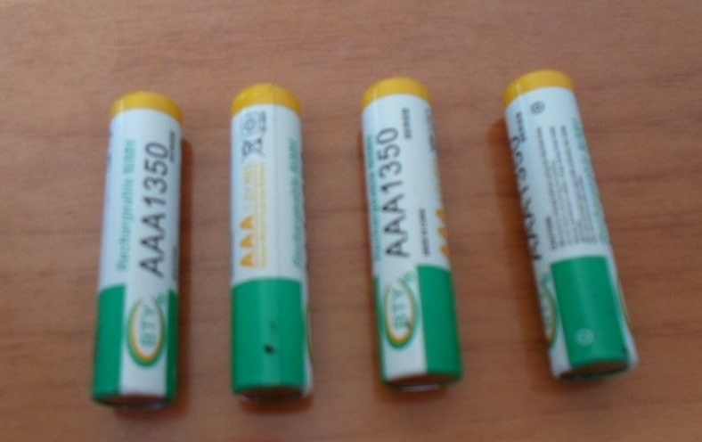
But as it turned out, conventional batteries for a long time are not enough. Therefore, I had to think about how to solve this problem, and make it so that I would not constantly buy new batteries. And a way out of this situation was found. I purchased rechargeable batteries of type AAA 1.2V 1300mA / h see Photo 27. They neatly fit the size of the on-board power compartment of the cyber robot, see Photo 28.
Nevertheless, the batteries were also gradually discharged and it was necessary to recharge them somehow.As a result, I developed a universal automatic charger. The schematic diagram of such a charger is shown in Fig. 3
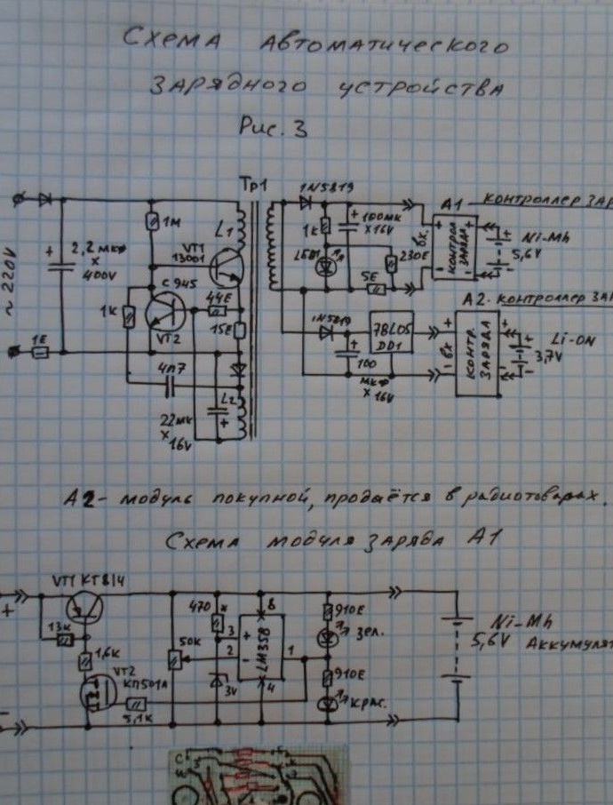
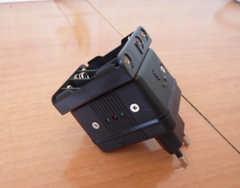
This device allows you to charge any rechargeable batteries, both Li-On and Ni-Mh, followed by an indication of the state of charge of the rechargeable batteries, and automatically turns off when the batteries are fully charged. A general view of the charger is shown in Photo 29.
Now, my project to develop a cyber robot has come true!