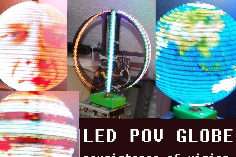
This tutorial is about how to build a POV globe with less. electronic components than other similar devices. Through the use of RGB LEDs with an integrated APA102 controller. This will save you the soldering of numerous wires. You can read more about them. These LEDs do not need an additional driver. They are connected directly to the microcontroller in two ways. This allows you to switch LEDs very quickly. To get a stable picture, SPI synchronization comes at a frequency of 10 MHz. Another plus of this design is the use of a flash card, which stores the image in BMP format.
1 Materials required
For the axis of the globe you will need:
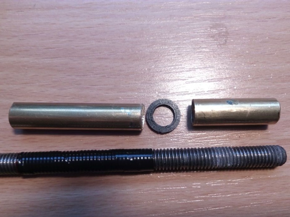
1. Stud with M8 thread and a length of 250 mm
2. Nut M8
3. Brass sleeve 10 mm and 100 mm long
4. Plastic washers 8 mm 2 pieces (STL files included)
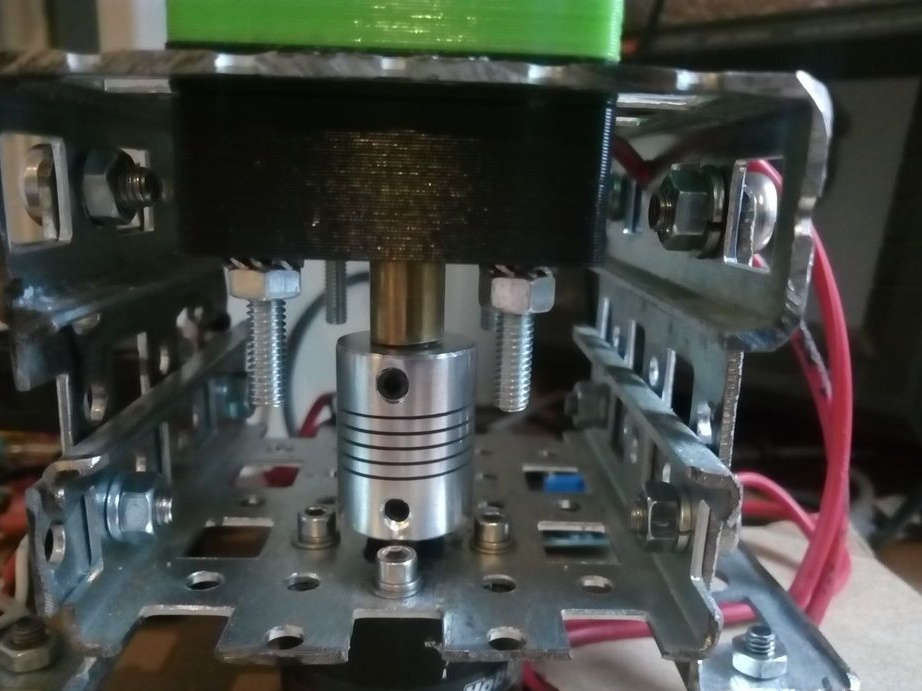
5. coupling for those who will use the stepper motor NEMA 17
To power the LED ring on the shaft, you will need
1. ball bearing 6300 (10x35x11)
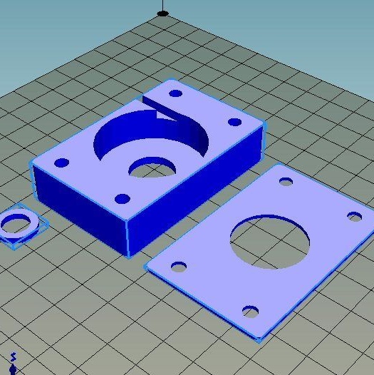
2. two brackets for bearings. Printed on a 3d printer or made of wood.
3. Four M4x40 bolts with nuts
4. Tips on wires 2 pcs 8mm
5. with a shaft diameter of 5mm
6. 4 bolts M4 for engine mounting
7. maybe a fan to it.
Alternatively, you can use any engine with the right torque and speed control. The motor used in this design has a maximum torque at a current of 50A, but the maximum current consumption during operation is only 18A.
To control the servomotor driver, use
1.
2. two buttons
Power supply 12V for motor and 5V for LEDs. As the power supply, you can use the old unit from the PC. You can buy a 12v / 5A power supply and connect to it
For the LED ring you will need:
1.664 LEDs 2 strips of 32 pieces
2. Capacitor 1000µF 10V
3. Hall sensor and magnet
4. The pull-up resistor 1k, 10k
5. The ring must be printed on a 3D printer or use a piece of PVC pipe
6. Plastic ties (100 mm)
7. A good glue that sticks together and does not fly apart at 2500 rpm
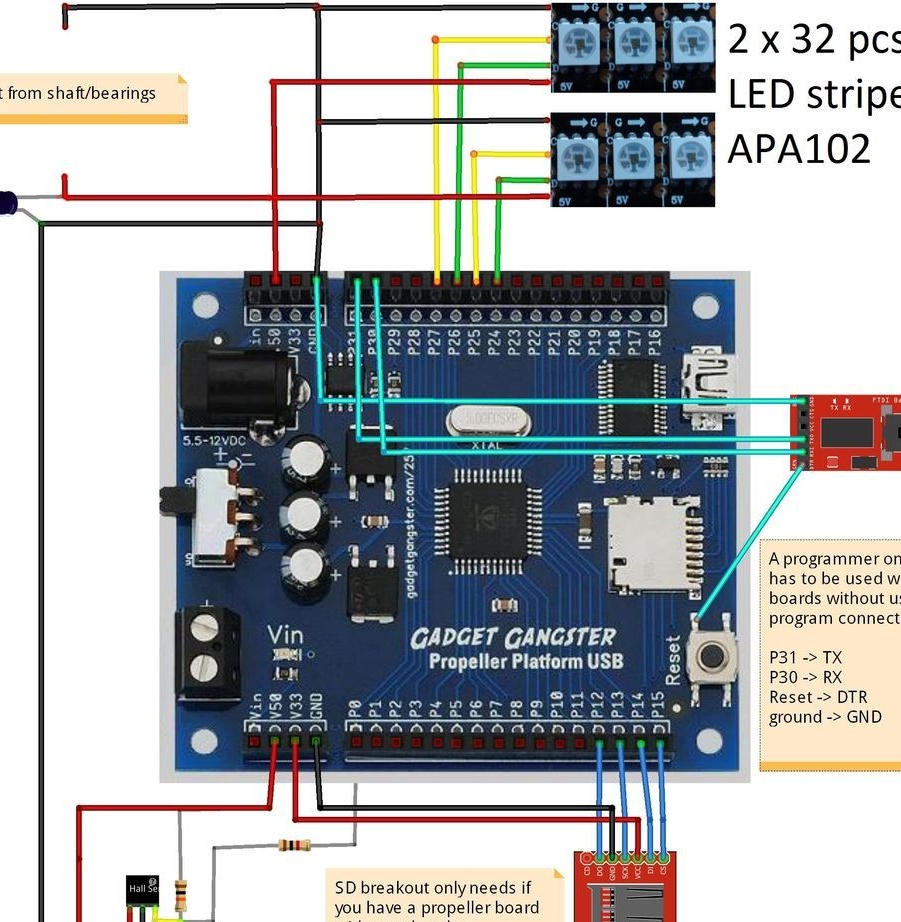
You will also need a Parallax Propeller Microcontroller. Or you can use another model controller, but additionally take a fee for. This controller is programmed and flashed as simple as Arduino. You will need a USB-TTL adapter to program both controllers.
Body.
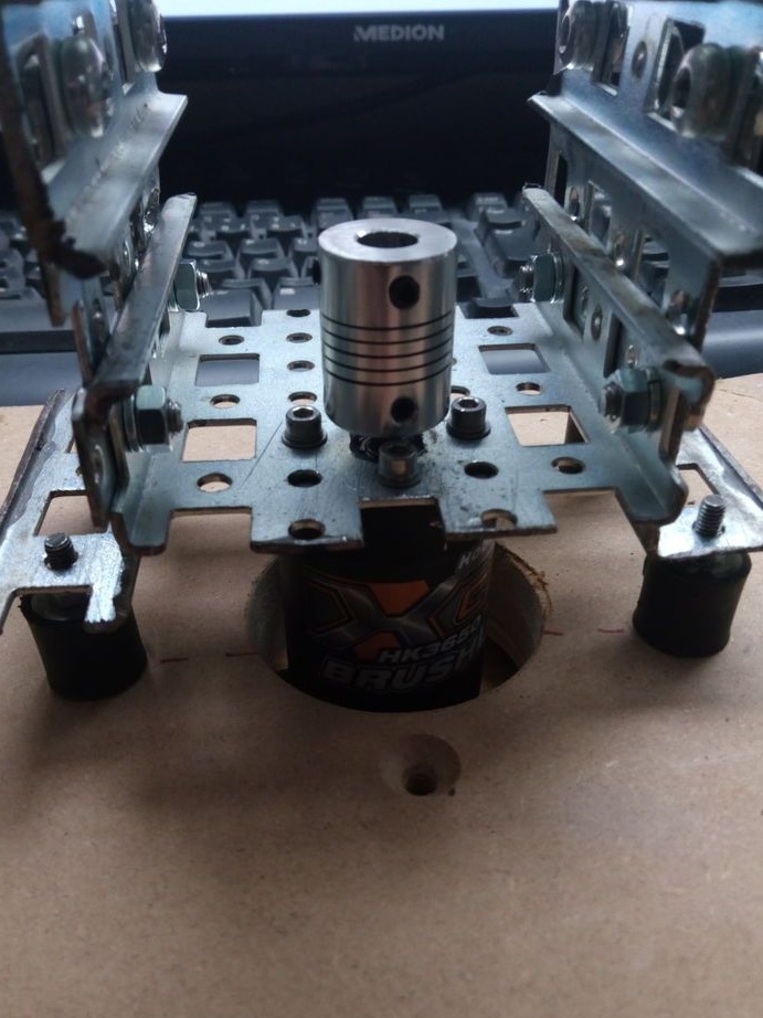
Housing for homemade You can take any hard enough. The most important thing is that the motor and bearings can be secured sufficiently reliably.
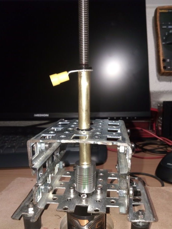
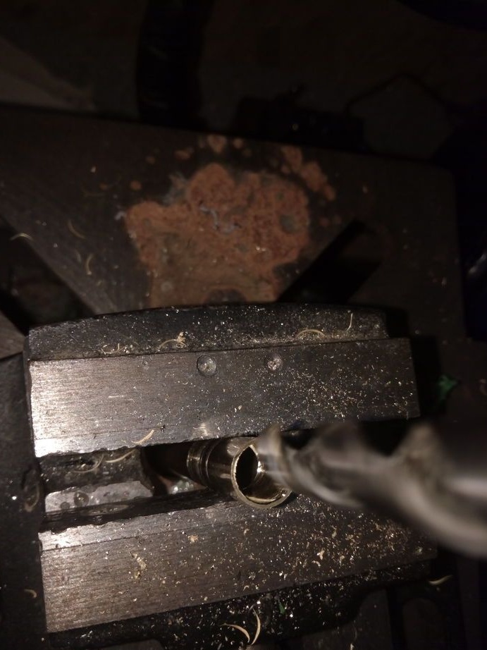
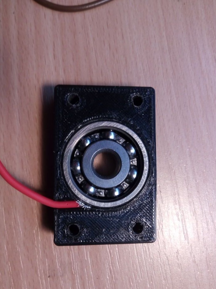
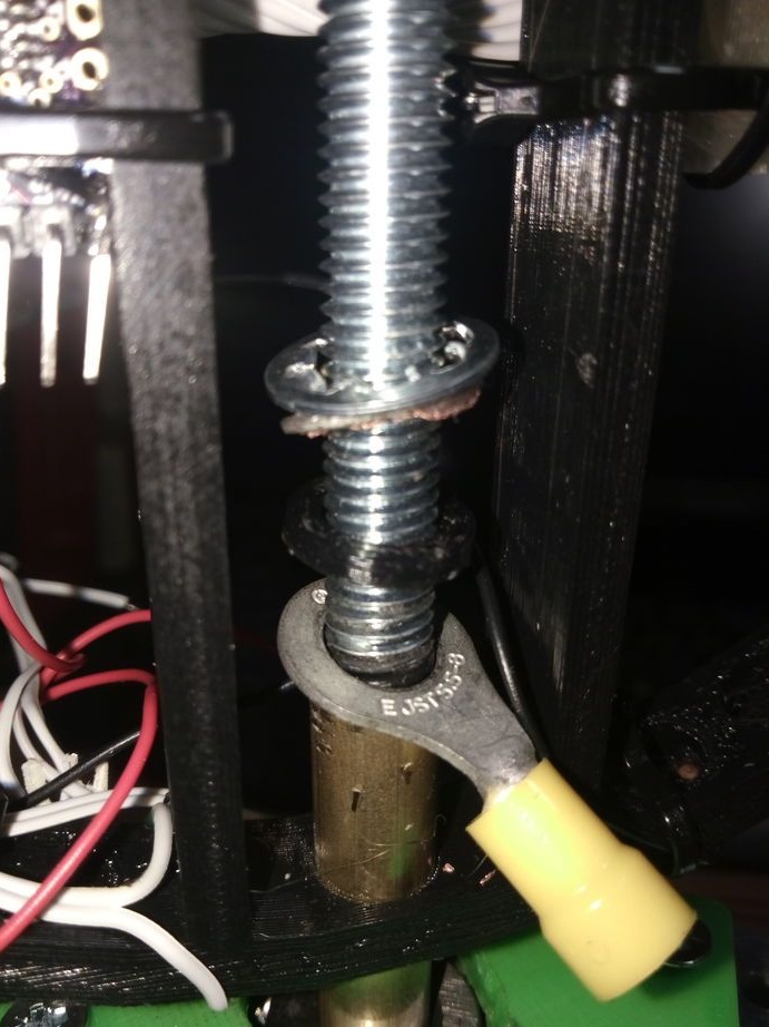
A 250 mm long stud is used for the drive shaft.The length of the brass bushings is 50 and 30 mm. Depends on ring size and shaft length. The upper and longer sleeve must be isolated from the stud, because it is used to supply plus power to the LEDs. To do this, wrap electrical tape on a hairpin or use heat shrink, two plastic washers will also be needed. The sleeve will need to be drilled to 8.5-9mm otherwise it will not fit. The other sleeve together with the rod forms a negative contact.
The minus power is placed in a special groove and pressed against the bearing in the bracket, which can be printed on a printer. Bracket STL file in archive.
Now you need to connect the electric motor, as shown in the diagram.
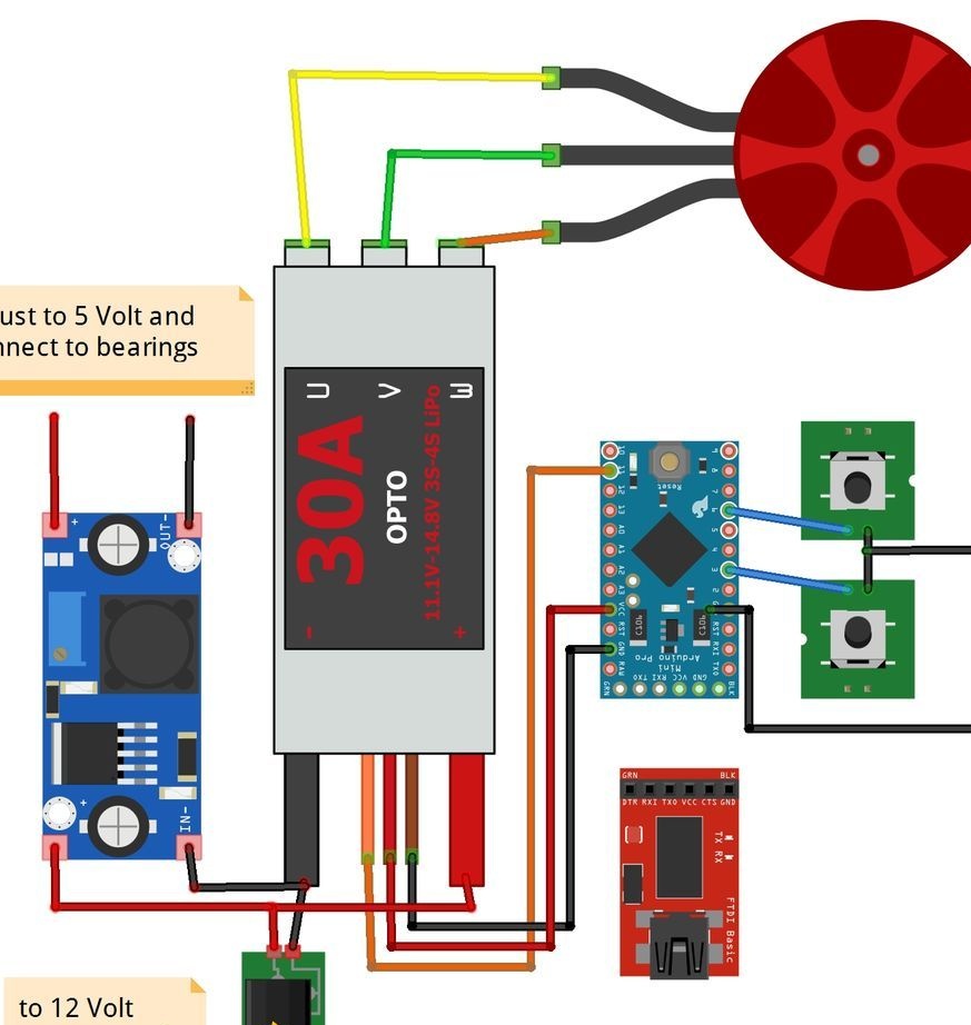
Two buttons on the diagram are used to adjust the speed. When you turn on the power, the ESC will receive a value of 500 μs. Press one of the buttons to turn on the engine. The sketch will take the value “StartPos = 625”. Later, when you adjust the speed, this value can be changed. Press the button for two seconds and the engine should stop.
Assembly of the core structure.
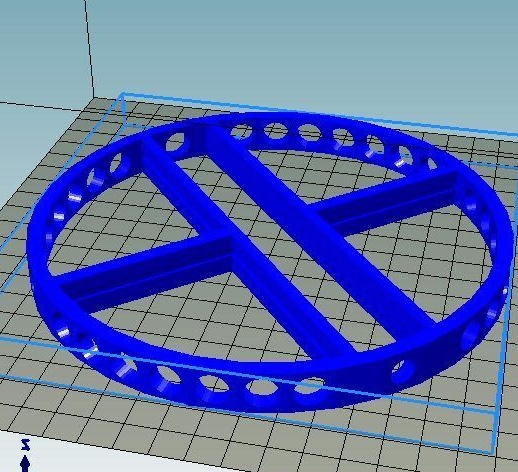

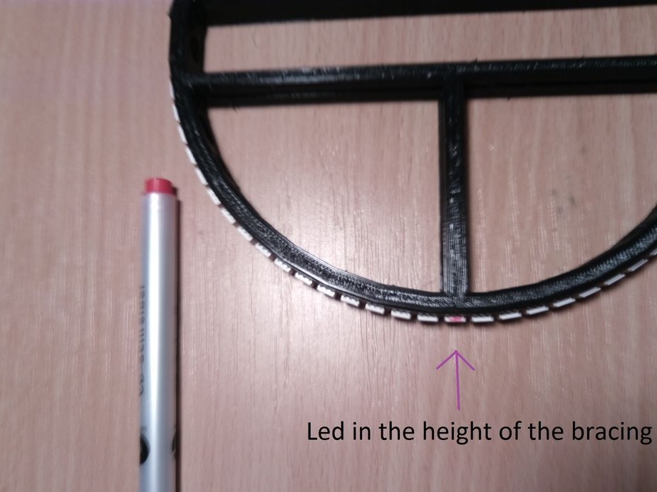
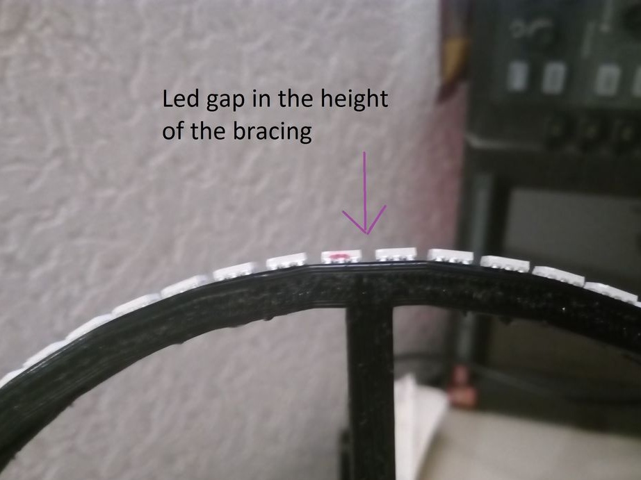
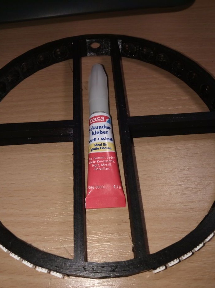
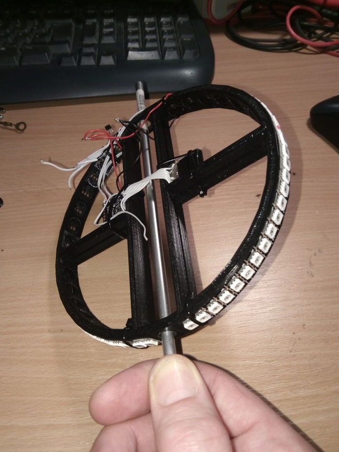
To do this, print the ring itself from the attached file. The author made many holes in it in order to reduce weight. You can use a piece of PVC pipe. Two strips of 32 LEDs are cut. Two strips of LEDs form even and odd lines. Arrange the tapes so that the LEDs of one strip are located between the LEDs of the other, but on the reverse side. After you fasten the tape, you can connect the controller board LEDs. And then you need to balance the entire assembly.
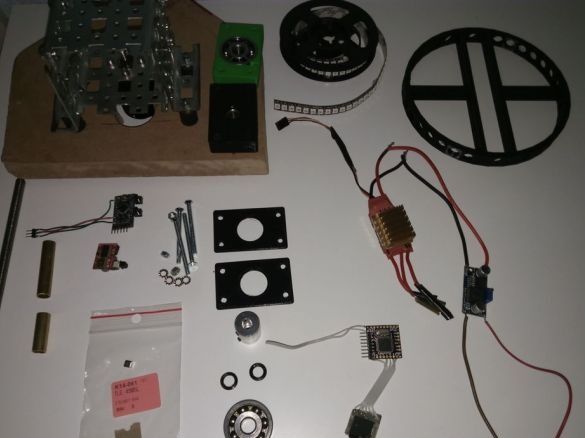
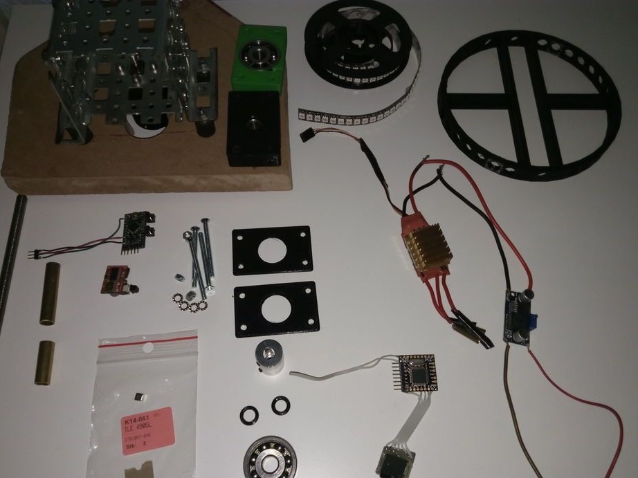
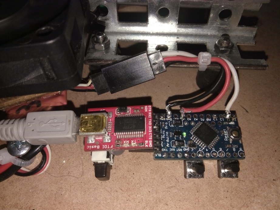
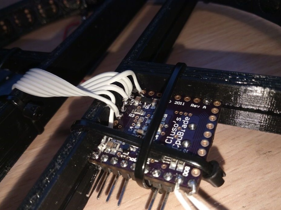
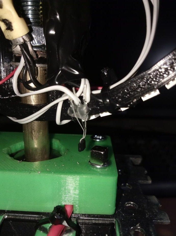
The following photos show how to connect all the components of the device together. The photo also shows the installed hall sensor with a magnet.
To program Parallax Propeller Microcontroller you need
DO NOT connect your equipment to a USB or serial port until you have installed the software. More details about uploading firmware to Parallax can be found
The author uses an older and, accordingly, less economical, in terms of energy consumption, MCU board because it cannot find new libraries on new controller cards.
After you collect and connect everything, you need to program the controller. The author does this with help. Files with firmware in the archive.
Now you can try to start the device. From the beginning, copy the test picture to the SD card and paste it into the slot.
• If you rotate the ring by hand, the LEDs should blink every time the hall sensor passes the magnet
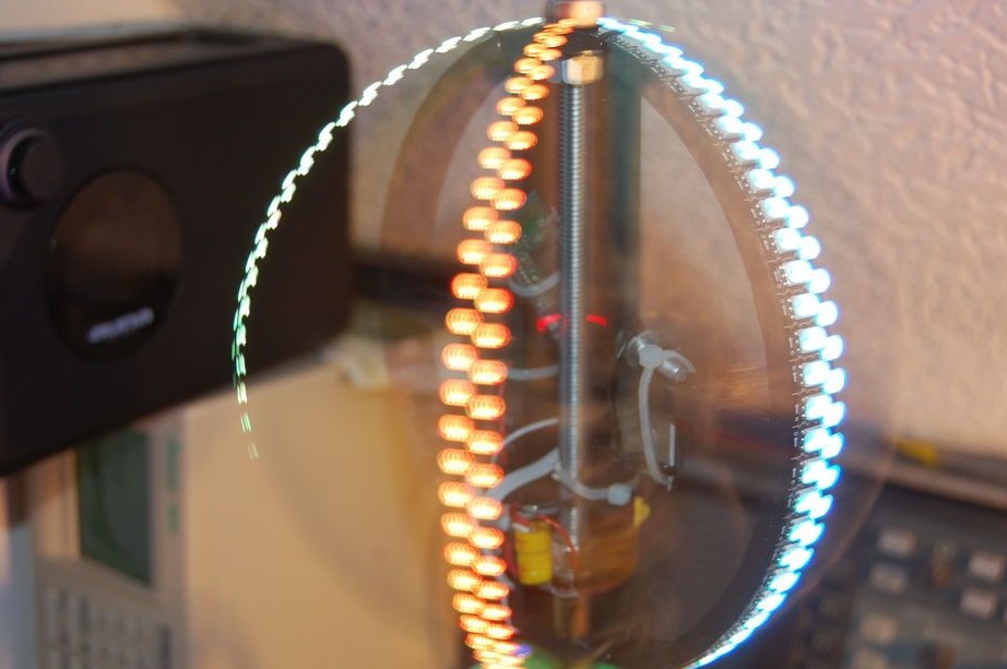
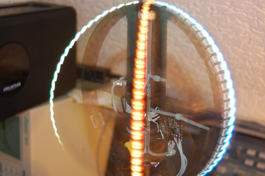
• Turn on the engine. Increasing the speed with the buttons, it is necessary to ensure that the LEDs light up as shown in 2 photos

• Connect the Arduino terminal to the motor controller.
• Remember the displayed value.
• Stop the engine
• Write the previously stored value to the variable "startPos"sketch POV_MotorControl
• Program the Arduino again.
The next time your motor starts immediately at the right speed. Now you can "Fill" on the map any image. To do this, you need to resize the image by 120x64 pixels, rotate the image counterclockwise by 90 degrees, and mirror vertically. Decrease the brightness of the image, as the LEDs are very bright. To do this, it is better to use gamma correction with a coefficient of 0.45.
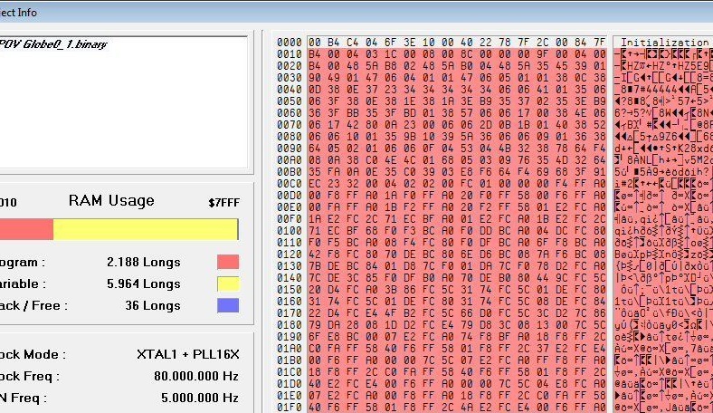
Save image as BPM 24 bit without compression. After all the manipulations, the output file will be the size 23094 byte.